 INNO 광섬유 온도 센서 ,온도 모니터링 시스템.
- Transformer winding temperature is the most critical parameter affecting insulation life and operational safety.
- Traditional methods such as 오일 온도 표시기 (완료), 권선 온도 표시기 (WTI), 그리고 RTD/thermocouple sensors each have inherent limitations in accuracy and direct measurement capability.
- 형광등 광섬유 온도 모니터링 시스템 based on GaAs sensing technology offer direct, 실시간(Real-time), and high-voltage-immune winding temperature measurement.
- 싱글 광섬유 온도 복조기 supports 1–64 channels, RS485 통신, 그리고 이상 25 수년간의 서비스 수명.
- This article provides a full comparison table, global application cases, and expert guidance for selecting the right monitoring solution.
목차
- What Is Transformer Winding Temperature?
- Causes and Hazards of Winding Temperature Rise
- International Standards and Temperature Limits
- Traditional Method: 오일 온도 표시기 (완료)
- Traditional Method: 권선 온도 표시기 (WTI)
- Traditional Method: Thermocouple and RTD Sensors
- 추천: 형광 광섬유 온도 모니터링 시스템
- Technical Comparison of All Four Methods
- 글로벌 적용사례
- Winding Temperature Protection and Control Logic
- 맞춤형 솔루션을 얻으세요
- 자주 묻는 질문 (자주 묻는 질문(FAQ))
- 부인 성명
1. What Is Transformer Winding Temperature?

변압기 권선 온도는 전력 변압기 내부의 구리 또는 알루미늄 도체의 실제 열 상태를 나타냅니다.. 다음을 포함하여 측정 가능한 모든 매개변수 중에서 오일 온도, 용존 가스 수준, 및 부하 전류 - 권선 핫스팟 온도는 변압기 상태와 남은 절연 수명을 결정하는 가장 중요한 단일 요소로 보편적으로 인식됩니다..
변압기가 부하를 전달할 때, 권선을 통해 흐르는 전류는 저항 손실을 발생시킵니다. (I²R 손실) 및 와전류 손실, 둘 다 열을 발생. 이 열은 권선 도체에 축적되며 절연 오일 및 냉각 시스템을 통해 방출되어야 합니다.. 가장 높은 온도에 도달하는 권선 구조 내 지점을 구불구불한 핫스팟. 안전한 적재 결정을 위해서는 이 핫스팟 온도를 정확하게 모니터링하는 것이 필수적입니다., 열 보호, 및 장기 자산 관리.
2. Causes and Hazards of Winding Temperature Rise
2.1 Primary Causes
Winding temperature rise is driven by several factors. Load current is the dominant contributor — as current increases, I²R losses increase proportionally with the square of the current. Eddy current and stray losses in the conductors and structural components generate additional heat. Ambient temperature and solar radiation directly affect the transformer’s ability to reject heat. 또한, degraded cooling systems — such as blocked radiators, failed fans, or deteriorated oil — reduce heat dissipation capacity and cause elevated winding temperatures.
2.2 Hazards of Excessive Winding Temperature
Excessive winding temperature accelerates the thermal degradation of cellulose insulation. According to the well-established Arrhenius aging model referenced in IEEE Std C57.91, the rate of insulation aging approximately doubles for every 6–7°C increase above the rated hot-spot temperature. Sustained overheating leads to reduced dielectric strength, formation of combustible gases, eventual insulation failure, and potentially catastrophic transformer damage. Reliable winding temperature monitoring is therefore not optional — it is a fundamental requirement for transformer protection.
3. International Standards and Temperature Limits
Several international standards govern transformer winding temperature limits and monitoring requirements. IEC 60076-2 specifies that the average winding temperature rise shall not exceed 65K above ambient for oil-immersed transformers, with a hot-spot temperature rise limit of 78K. IEEE Std C57.12.00 similarly defines a 65°C average winding rise for most classes. IEEE Std C57.91 provides detailed thermal loading guidelines, hot-spot calculation methods, and insulation aging equations. IEC 60354 (now absorbed into IEC 60076-7) offers loading guidance based on thermal modeling. These standards collectively establish that continuous winding hot-spot temperatures should generally remain below 110–120°C for normal life expectancy, with the maximum permissible value depending on the insulation class and loading duration.
4. Traditional Method: 오일 온도 표시기 (완료)
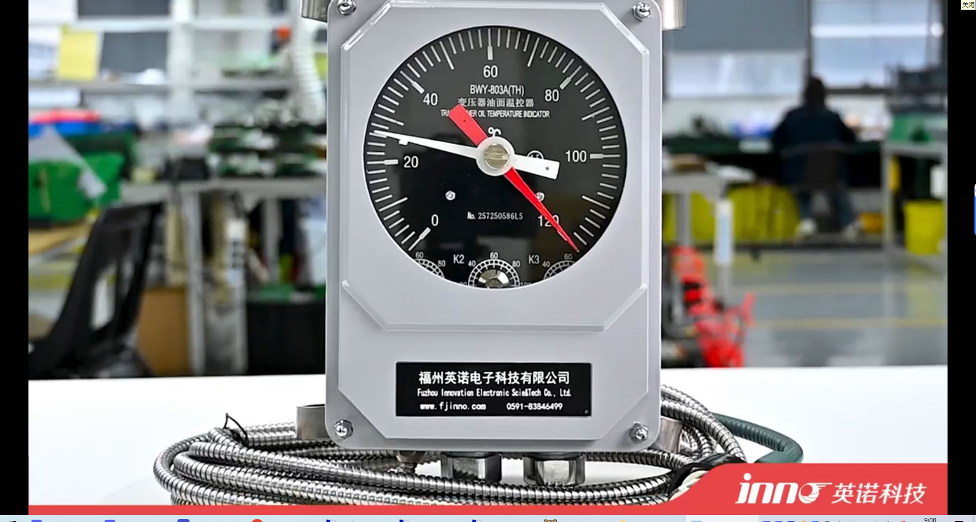
4.1 작동 원리
안 오일 온도 표시기 (완료), also commonly referred to as an 오일 온도계 또는 oil temperature gauge, measures the temperature of the insulating oil at or near the top of the transformer tank. The most common type uses a liquid-expansion (mercury or organic-filled) capillary system. A sensing bulb is inserted into a thermometer pocket welded on the transformer tank. As the oil temperature changes, the liquid in the bulb expands or contracts, driving a pointer on the dial gauge via the capillary tube.
4.2 Typical Parameters
기준 완료 devices offer a measurement range of 0–150°C, with an accuracy of approximately ±3–5°C. They typically include adjustable alarm and trip contacts (commonly set at 85°C and 95°C for top-oil temperature). The capillary length is usually available from 1 m to 20 m. Response time is relatively slow, typically in the range of several minutes.
4.3 제한사항
이 오일 온도 표시기 measures only the top-oil temperature, which does not directly represent the winding hot-spot temperature. The actual winding hot spot can be 20–40°C higher than the measured oil temperature. Mechanical components are subject to drift and aging over time, and the device cannot be easily integrated into modern digital monitoring systems without additional signal converters.
5. Traditional Method: 권선 온도 표시기 (WTI)
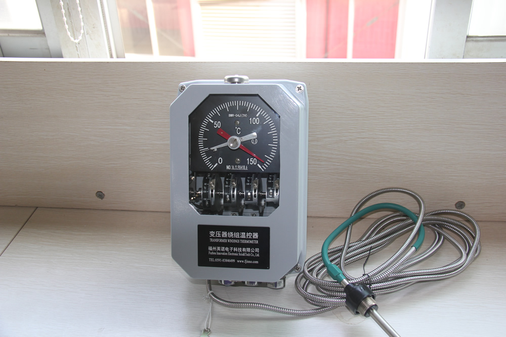
5.1 작동 원리
A 권선 온도 표시기 (WTI) uses a thermal imaging (simulation) method to estimate the winding hot-spot temperature without directly measuring the winding conductor. A current transformer (코네티컷) on the bushing provides a signal proportional to the load current. This signal feeds a small heating element coiled around the sensing bulb of a thermometer pocket. The combination of the ambient oil temperature and the thermal contribution from the heating resistor simulates the thermal gradient between the oil and the winding, producing an indirect estimate of the winding hot-spot temperature.
5.2 Calibration and Setup
During factory heat-run testing, 그만큼 WTI is calibrated by adjusting the heating resistor current to match the measured winding-to-oil gradient at rated load. This calibration is specific to one loading condition. In the field, the relationship between load current and actual temperature gradient may deviate from the factory setting due to varying cooling conditions, 오일 노화, and non-linear thermal dynamics.
5.3 Typical Parameters
표준 권선 온도 표시기 provides a display range of 0–200°C with an accuracy of approximately ±3–5°C for the simulated value. It includes two to four adjustable contacts for fan start, pump start, 경보, 및 트립 기능. Response time is moderate, typically 5–15 minutes due to the thermal inertia of the simulation element.
5.4 제한사항
왜냐하면 WTI relies on an indirect thermal model rather than a direct measurement, its reading is an approximation. Under transient loading conditions, 과부하 이벤트, or when cooling system performance changes, the WTI may significantly deviate from the actual winding temperature. It is also vulnerable to calibration drift over the transformer’s service life.
6. Traditional Method: Thermocouple and RTD Sensors
6.1 작동 원리
열전대 센서 (typically Type T or Type K) generate a voltage proportional to the temperature difference between the sensing junction and a reference junction. 백금 저항 온도 감지기 (Pt100 RTD) measure temperature by detecting the change in electrical resistance of a platinum element. Both types can be embedded within the transformer winding during manufacturing to provide direct temperature readings of the conductor.
6.2 Typical Parameters
A Pt100 RTD offers an accuracy of ±0.5–1.5°C across a range of −200°C to +600°C. Thermocouples provide accuracy of ±1–2.5°C. Response times vary from 1 받는 사람 10 seconds depending on the encapsulation. Both types require metallic lead wires routed from the winding interior out through the transformer structure.
6.3 제한사항
The primary drawback of embedded thermocouples and RTDs is that metallic lead wires introduce a conductive path into the high-voltage environment of the transformer winding. This creates insulation coordination challenges and increases the risk of dielectric failure. Electromagnetic interference from the transformer’s magnetic field can also affect signal integrity. 또한, these sensors can typically only be installed during manufacturing, making retrofit applications difficult.
7. 추천: 형광 광섬유 온도 모니터링 시스템

7.1 Why Fluorescent Fiber Optic Technology Is Recommended
Among all available methods, 그만큼 형광 광섬유 온도 모니터링 시스템 is the only technology that provides truly direct, real-time measurement of transformer winding temperature with complete immunity to electromagnetic interference. Unlike OTI and WTI, which rely on indirect estimation, and unlike metallic thermocouples or RTDs, which compromise insulation integrity, 형광성 광섬유 센서 use all-dielectric optical fibers that are inherently insulating and introduce zero electrical risk into the high-voltage winding environment.
7.2 GaAs Fluorescent Sensing Principle
이 형광성 광섬유 온도 감지기 operates based on the temperature-dependent fluorescence decay characteristics of a 갈륨비소 (GAAS) semiconductor crystal bonded to the tip of an optical fiber. When pulsed light from the 광섬유 복조기 excites the GaAs crystal, it emits fluorescent light whose decay time varies predictably with temperature. The demodulator analyzes the decay curve to determine the precise temperature at the sensing point. This is a point-type measurement method, providing a discrete and accurate temperature value at each sensor location.
7.3 시스템 구성
완전한 형광 광섬유 온도 모니터링 시스템 consists of five key components:
광섬유 온도 복조기 (송신기)

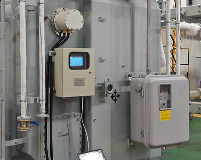
이 광섬유 온도 복조기 is the central processing unit of the system. 여기 광 펄스를 생성합니다., receives the returned fluorescent signal, and computes the temperature value. A single demodulator supports 1 받는 사람 64 측정 채널, making it suitable for monitoring multiple winding hot spots simultaneously. It provides an RS485 통신 인터페이스 (모드버스 RTU) for integration with DCS, SCADA, or transformer monitoring IEDs. All channel configurations and communication parameters are customizable per project requirements.
Fluorescent Fiber Optic Cable

이 형광성 광섬유 cable transmits excitation and return light between the demodulator and the sensing probe. It is fully dielectric, 내유성, and designed for long-term immersion in transformer insulating oil. The cable length is available from 0 받는 사람 20 meters to accommodate various transformer sizes and routing requirements.
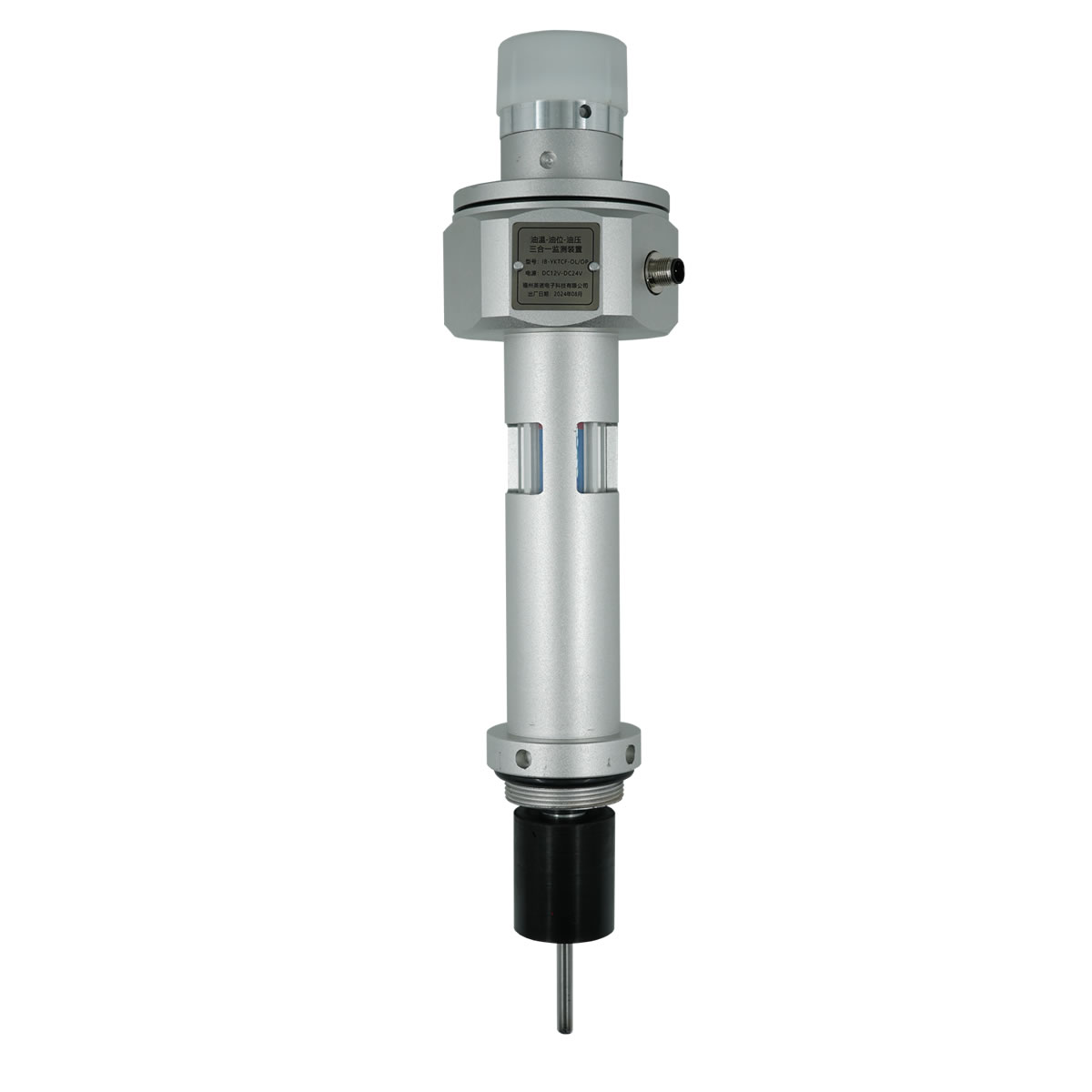
Sensing Probe
이 fluorescent temperature sensing probe contains the GaAs crystal and is the point of actual temperature measurement. The probe features a compact diameter of 2–3 mm and can be customized for specific installation requirements. It withstands continuous operating voltages exceeding 100 케이 V, making it fully qualified for direct placement against winding conductors in high-voltage and ultra-high-voltage transformers.
디스플레이 모듈
이 온도 디스플레이 모듈 provides local visual indication of all channel readings, 알람 상태, 및 시스템 진단. It is typically panel-mounted on the transformer control cabinet.
모니터링 소프트웨어
이 온도 모니터링 소프트웨어 runs on a connected PC or server and provides real-time trending, 기록 데이터 로깅, 알람 관리, 및 보고서 생성. It enables centralized remote monitoring of winding temperatures across multiple transformers.
7.4 Installation in Transformer Windings
이 형광성 광섬유 감지 프로브 is installed during transformer manufacturing by embedding it directly at the calculated hot-spot location within the winding structure, typically between insulated conductors at the top of the high-voltage or low-voltage winding. 이 광섬유 케이블 is routed through the insulation structure and exits the transformer through a dedicated fiber optic feedthrough fitting on the tank wall. Because the entire sensor is non-metallic and non-conductive, it requires no special insulation coordination and introduces no risk to the transformer’s dielectric performance.
8. Technical Comparison of All Four Methods
The following table provides a comprehensive side-by-side comparison of all four transformer winding temperature monitoring methods discussed in this article.
| 매개 변수 | 완료 (오일 온도 표시기) | WTI (권선 온도 표시기) | 열전대 / RTD | 형광성 광섬유 (GAAS) |
|---|---|---|---|---|
| 측정 유형 | 간접 (기름만) | 간접 (열 시뮬레이션) | 직접 (포함) | 직접 (포함) |
| 정밀 | ±3–5°C | ±3–5°C | ±0.5–2.5°C | ±0.5~1°C |
| 측정 범위 | 0–150°C | 0–200°C | −200 to +600°C | −40 to +260°C |
| 응답 시간 | Several minutes | 5–15 minutes | 1–10 seconds | <1 초 |
| EMI 내성 | 보통의 | 보통의 | 가난한 | 완벽한 (완전 유전체) |
| 내전압 | 해당 없음 (외부) | 해당 없음 (외부) | 제한된 | >100 케이 V |
| 프로브 직경 | Bulb type | Bulb type | 3-6mm | 2-3mm (맞춤형) |
| 센서 소재 | 메탈릭 | 메탈릭 | 메탈릭 | All-dielectric (insulating) |
| Cable/Fiber Length | 1–20 m | 1–20 m | 신호 손실로 인해 제한됨 | 0–20 m |
| 채널 용량 | 하나의 | 하나의 | 다지점 (열광한) | 1–복조기당 64개 채널 |
| 통신 | Contacts only (비슷한 물건) | Contacts only (비슷한 물건) | 아날로그 신호 / 4-20mA | RS485 시리즈 (모드버스 RTU), 맞춤형 |
| 서비스 수명 | 10-15년 | 10-15년 | 10-20년 | >25 년 |
| 개조 기능 | 쉬운 | 쉬운 | 어려운 | Factory installation recommended |
| 상대 비용 | 낮은 | Low–Medium | 중간 | Medium–High |
As shown in the table, 그만큼 형광 광섬유 온도 모니터링 시스템 delivers the best combination of measurement accuracy, 응답 속도, 전자기 내성, dielectric safety, and long service life — making it the clear choice for critical power transformers where reliable winding temperature data is essential.
9. 글로벌 적용사례

Fluorescent fiber optic winding temperature monitoring systems have been deployed in a wide range of transformer applications worldwide. The following are representative examples demonstrating proven performance across different voltage classes and operating environments.
9.1 High-Voltage Power Transformers (110 kV – 220 케이 V)
Multiple utility-class 110 kV 및 220 kV power transformers in large-scale substation projects across Asia, 중동, and South America have been equipped with 형광성 광섬유 센서 embedded at the calculated hot-spot locations. These installations enabled real-time winding temperature visibility and dynamic loading optimization, replacing older WTI-based thermal estimates.
9.2 Ultra-High-Voltage (UHV) Transmission Transformers
In ultra-high-voltage transmission projects operating at 500 kV 이상, the all-dielectric nature of the 형광성 광섬유 감지 프로브 is a critical advantage. These transformers demand absolute insulation integrity, and conventional metallic sensors are not acceptable. Fluorescent fiber optic systems have been successfully installed in multiple UHV transformer units, providing continuous hot-spot monitoring under extreme voltage stress.
9.3 Industrial and Traction Transformers
In industrial applications such as arc furnace transformers and railway traction transformers, highly variable and cyclic loading profiles make accurate winding temperature monitoring essential. 형광성 광섬유 시스템 provide the fast response time (<1 초) needed to track rapid thermal transients, enabling precise thermal protection under dynamic operating conditions.
9.4 Renewable Energy and Offshore Transformers
Transformers serving wind farms and offshore platforms operate in harsh and remote environments where maintenance access is limited. 광섬유 온도 모니터링 with remote data access via RS485 and SCADA integration allows operators to manage thermal performance without physical site visits, significantly reducing operational risk and maintenance cost.
10. Winding Temperature Protection and Control Logic

Winding temperature measurements are used to drive protective actions and cooling control. In a typical implementation, the monitoring system triggers the following responses based on configurable temperature thresholds.
10.1 Cooling System Activation
When the winding temperature reaches a first-stage threshold (commonly 85–95°C), the monitoring system sends a command to start additional cooling fans or oil pumps. This activates supplementary cooling stages (ONAF or ODAF) to increase heat dissipation capacity.
10.2 경보
2단계 임계값 (일반적으로 105~110°C) 고온 경보를 발령합니다, 이는 변압기 제어판에서 로컬로 표시되고 운영자 작업을 위해 SCADA 시스템으로 원격으로 전송됩니다..
10.3 여행
온도가 계속 상승하여 위험 임계값에 도달하는 경우 (일반적으로 120~130°C), 변압기의 전원을 차단하고 돌이킬 수 없는 절연 손상을 방지하기 위해 트립 명령이 내려집니다.. 이 신호는 건식 접점 또는 디지털 통신을 통해 변압기 보호 계전기와 인터페이스됩니다..
10.4 SCADA 및 DCS 통합
이 형광성 광섬유 온도 복조기 RS485를 통해 실시간 온도 데이터 전송 (모드버스 RTU) 변전소 SCADA 시스템 또는 플랜트 DCS에. 이를 통해 중앙 집중식 모니터링이 가능합니다., 과거 동향, 여러 변압기에 걸쳐 조정된 열 관리.
11. 맞춤형 솔루션을 얻으세요
Every transformer application has unique requirements for channel count, fiber cable routing, display configuration, 및 시스템 통합. Our engineering team at 핀노 provides tailored 형광 광섬유 온도 모니터링 솔루션 for transformer manufacturers, 유용, and industrial operators worldwide.
Whether you need a standard 4-channel system for a distribution transformer or a 64-channel configuration for a large power transformer bank, we deliver fully customized hardware and software packages with complete technical support.
오늘 저희에게 연락하세요 to discuss your project requirements, request a quotation, or schedule a technical consultation. 방문하다 www.fjinno.net 자세한 내용은.
12. 자주 묻는 질문 (자주 묻는 질문(FAQ))
1분기: What is the difference between oil temperature and winding temperature in a transformer?
Oil temperature represents the temperature of the insulating oil, typically measured at the top of the tank. Winding temperature is the actual temperature of the copper or aluminum conductor in the winding, which is always higher than the oil temperature due to the thermal gradient. The hot-spot winding temperature can be 20–40°C above the top-oil temperature under full load.
2분기: Why is a WTI not considered a direct measurement method?
A winding temperature indicator uses a thermal simulation approach. It estimates winding temperature by adding a current-dependent thermal contribution to the measured oil temperature. It does not have a sensor placed on the actual winding conductor, so it cannot capture the true hot-spot temperature under all operating conditions.
3분기: How does a fluorescent fiber optic sensor withstand high voltage inside a transformer?
The fluorescent fiber optic sensor is made entirely of non-metallic, dielectric materials — glass fiber and a GaAs crystal tip. It does not conduct electricity and therefore introduces no conductive path into the insulation structure. This allows it to operate safely at voltage levels exceeding 100 케이 V.
4분기: Can fluorescent fiber optic sensors be retrofitted into an existing transformer?
Fluorescent fiber optic sensors are most effectively installed during the transformer manufacturing process, when they can be precisely positioned at the calculated hot-spot location within the winding. Retrofitting into a sealed, oil-filled transformer is not practical without removing the active part. 기존 변압기의 경우, WTI or external monitoring methods are typically used.
Q5: How many sensing points can one demodulator handle?
A single fluorescent fiber optic temperature demodulator supports 1 받는 사람 64 채널. Each channel connects to one sensing probe for independent point-type temperature measurement. The channel count is configurable based on the specific project needs.
Q6: What communication protocol does the system use?
The standard communication interface is RS485 using the Modbus RTU protocol, which is widely compatible with substation SCADA systems, DCS 플랫폼, and intelligent electronic devices (IED). Other communication options can be customized upon request.
Q7: What is the expected service life of a fluorescent fiber optic temperature sensor?
The fluorescent fiber optic sensing probe and fiber cable are designed for a service life exceeding 25 년, which matches or exceeds the typical design life of a power transformer. The all-glass construction and sealed GaAs crystal are resistant to degradation in transformer oil environments.
Q8: What international standards apply to transformer winding temperature limits?
The primary standards are IEC 60076-2 (온도 상승 한계), IEC 60076-7 (로딩 가이드), IEEE Std C57.12.00 (general requirements), and IEEE Std C57.91 (loading and thermal modeling). These standards define maximum allowable winding rise temperatures and hot-spot limits for various loading conditions.
Q9: Is the fluorescent fiber optic sensor affected by electromagnetic interference?
아니요. Because the sensor is entirely non-metallic and the measurement principle is based on optical signals rather than electrical signals, it is completely immune to electromagnetic interference from the transformer’s magnetic field, 과도 스위칭, or nearby high-voltage equipment.
Q10: How do I determine the correct number of sensors needed for my transformer?
The number of sensing points depends on the transformer design, 전압 등급, 냉각 유형, and the number of windings to be monitored. 일반적으로, sensors are placed at the calculated hot-spot locations of each major winding (HV, LV, and tertiary if applicable). Our engineering team can assist with sensor placement planning based on the thermal design data of your specific transformer. 다음 주소로 문의하세요. www.fjinno.net for technical support.
13. 부인 성명
The information provided in this article is intended for general educational and reference purposes only. While every effort has been made to ensure the accuracy and reliability of the content at the time of publication, FJINNO makes no warranties or representations, 명시적이든 묵시적이든, 완전성에 관해서, 정밀, or suitability of the information for any specific application. Transformer design, 설치, and monitoring practices must comply with applicable local and international standards, 규정, and engineering best practices. Readers are advised to consult qualified engineers and refer to the latest editions of relevant standards before making any design or purchasing decisions. FJINNO shall not be liable for any direct, 간접적인, or consequential damages arising from the use of or reliance on the information presented in this article. 프로젝트별 기술 안내, please contact our engineering team at www.fjinno.net.

광섬유 온도 센서, 지능형 모니터링 시스템, 중국에 분포된 광섬유 제조업체
|
 |
 |