 INNO 光ファイバー温度センサー ,温度監視システム.
- 温度監視用の光ファイバーソリューション are complete sensing systems that use optical fiber — rather than metallic conductors — to measure temperature continuously and in real time, making them the standard choice for environments where conventional electronic sensors cannot operate safely or reliably.
- Because the sensing medium is light through glass, fiber optic temperature solutions are inherently immune to electromagnetic interference, create no conductive path into monitored equipment, and operate safely at any voltage level — including direct contact with live high-voltage conductors.
- Two technologies address two fundamentally different measurement geometries: 蛍光ファイバー光センシング 正確に, real-time monitoring at specific critical points, そして 分散型光ファイバー温度検知 (DTS) for continuous thermal mapping along the full length of a cable route.
- Fluorescence sensing is the right solution when the monitoring targets are known locations on equipment — switchgear contacts, 変圧器巻線, battery cells — and accuracy, 応答速度, and electrical isolation are the primary requirements.
- DTS is the right solution when coverage must extend across kilometers of infrastructure without blind spots, and the location of a thermal anomaly is not known in advance.
- Both technologies communicate over RS485 / Modbus RTU と SCADA との統合, DCS, and building management systems without custom hardware.
- 製造元 福州イノベーション電子科学&テック株式会社, 株式会社. — fiber optic sensing specialist since 2011.
1. とは何ですか 温度監視用の光ファイバー ソリューション?

温度監視用の光ファイバーソリューション are complete instrumentation systems that use optical fiber as the sensing medium — measuring temperature through changes in the properties of light rather than through electrical signals. A fiber optic temperature solution replaces the metallic conductors, voltage sources, 感知点と測定器の間に光のみを伝えるパッシブグラスファイバーを使用した従来の温度測定の通電測定回路. その結果、電気特性が根本的に異なる温度監視アプローチが誕生しました。, 物理的な制約, 金属ベースのセンサー技術による長期的な動作挙動.
光ファイバーと従来の電子温度測定の違いは程度の問題ではなく、種類の違いです。. 熱電対は小さな電圧を生成して温度を測定します; RTD は電気抵抗を変化させることで測定します; 半導体センサーは接合電圧の変化を通じて測定します. All three require a metallic conductor to carry an electrical signal from the measurement point back to the instrument. That metallic conductor is a conductive path — and in environments involving high voltage, 強い電磁場, 爆発性雰囲気, or intense magnetic fields, a conductive path from the measurement point to ground is either a safety hazard, a source of measurement error, または両方.
あ fiber optic temperature sensing solution eliminates the conductive path entirely. The glass fiber carries light in both directions; no voltage, 電流が流れていない, and no electrical energy of any kind travels to or from the sensing point through the fiber. This makes fiber optic solutions the only contact temperature measurement technology that can operate safely and accurately inside live high-voltage switchgear, in the winding of a power transformer under load, in an MRI scanner’s magnetic field, in a Zone 1 hazardous area, or in any other environment where conventional sensors are unsafe, 信頼できない, or physically impossible to install.
2. Why Light Outperforms Electricity as a Sensing Medium: The Core Physical Advantages

The superiority of optical fiber over metallic conductors as a temperature sensing medium follows directly from the physical properties of glass and light. These are not engineering refinements — they are fundamental characteristics of the sensing medium that determine what is and is not possible in each class of application.
No Conductive Path — Complete Electrical Isolation at Any Voltage
Glass optical fiber is a dielectric material. It conducts light and nothing else. あ 光ファイバー温度プローブ 通電中の高電圧バスバーに直接設置, 数百キロボルトで通電される変圧器の巻線, または、数千アンペアを流す牽引電力導体が監視機器への導電経路を提供しません。. システム電圧に関係なく、測定システムを介した検出点と接地間の電気的破壊の可能性はありません, 故障電流レベル, または周囲の絶縁体の誘電状態. これは超過できる絶縁定格ではありません; それは感知媒体の物理的特性です.
電磁干渉に対する固有の耐性
Electromagnetic interference corrupts electronic temperature measurements by inducing voltages in the metallic signal conductors that the measurement circuit cannot distinguish from the actual sensor signal. In environments with strong power-frequency magnetic fields — switchgear panels, motor rooms, transformer vaults, induction heating installations — the induced voltage in a thermocouple lead or RTD cable can be larger than the measurement signal itself, producing temperature errors of tens of degrees. あ fiber optic thermal sensing system is immune to this mechanism at a physical level: no voltage can be induced in glass, and the light signal traveling through the fiber is unaffected by any external electromagnetic field.
Intrinsically Safe at the Measurement Point
In hazardous areas where flammable gases, 蒸気, or dusts are present, any electrical device must be assessed as a potential ignition source. The passive, zero-energy nature of a fiber optic temperature sensor probe means there is no electrical energy at the sensing point under any operating condition — including instrument power failure, signal cable short circuit, or component fault in the monitoring instrument. The probe cannot ignite a flammable atmosphere because it carries and stores no energy. This intrinsic safety characteristic simplifies hazardous area classification and documentation significantly compared to any electrically active sensor technology.
Long-Term Measurement Stability Without Recalibration
Conventional electronic sensors drift. Thermocouple output shifts as the thermoelectric material ages and oxidizes at elevated temperatures. 熱サイクルによるセンシングワイヤの加工硬化に伴って RTD 抵抗が変化する. 半導体センサーは放射線や長時間の熱にさらされると劣化します。. これらの各ドリフトメカニズムにより測定誤差が増大し、定期的な再校正を通じて管理する必要があります。これにはセンサーへのアクセスが必要です。, 監視の中断, および参照標準との比較.
基礎となる物理的原理 光ファイバー温度測定ソリューション — 特に蛍光寿命のアプローチでは — 同じようにドリフトしない. 測定される光学特性と温度との関係は、センシング材料の安定した特性です, 時間の経過とともに劣化する校正ではありません. A fiber optic sensing system installed today will produce the same accurate measurement twenty-five years from now under the same thermal conditions, without any recalibration intervention.
3. Two Technologies, Two Measurement Geometries: Fluorescence vs Distributed Sensing

内で 温度監視用の光ファイバーソリューション, two distinct physical principles address two fundamentally different operational requirements. Choosing between them is not primarily a question of performance specifications — it is a question of measurement geometry: what shape is the problem you need to solve?
Point Measurement vs Route Measurement
Some temperature monitoring problems are defined by specific locations. The hottest point on a circuit breaker contact. The winding hot spot in a particular transformer phase. The cell at the end of a battery rack that runs warmest under charge. These are point measurement problems — the engineering team knows exactly where to put the sensor, and the value of the monitoring system lies in the accuracy, speed, and reliability of the reading at each known location.
Other temperature monitoring problems are defined by routes or areas. A 15-kilometer underground cable tunnel. A buried pipeline across a rural landscape. A railway tunnel where a fire could start anywhere along its length. These are route measurement problems — the critical characteristic is not the accuracy of the reading at a single point but the absence of blind spots across the entire monitored length. No pre-identified location can be specified because the fault could develop anywhere.
Fluorescence fiber optic sensing solves point measurement problems. 分散型光ファイバー温度検知 (DTS) solves route measurement problems. Both use optical fiber as the sensing medium and share all the physical advantages described above — but they work on different principles and produce fundamentally different types of data.
4. 蛍光ファイバーによる温度モニタリング: Precision at Every Critical Point

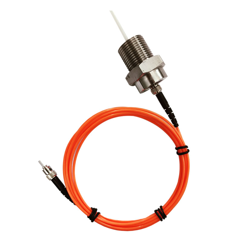
あ fluorescence fiber optic temperature monitoring solution works by exciting a rare-earth phosphor element at the tip of the sensing probe with a brief pulse of light from the instrument. The phosphor absorbs the excitation energy and re-emits it as fluorescence — and the time constant of that fluorescence decay, known as the lifetime (t), shifts in a stable, predictable relationship with temperature. 機器はτを測定し、それを校正された温度値に変換します。.
このアプローチのエンジニアリング上の重要な利点は、測定が光の強度ではなく時間、つまり蛍光が減衰するまでにかかる時間に基づいていることです。. これは、システム内の光パワーを低下させるもの、つまりファイバーの老朽化が原因であることを意味します。, コネクタの汚れ, 光源の調光 - 測定温度には影響しません. 特定の温度での減衰時間は、蛍光体材料の固定された物理的特性です。; 光学系が古くなっても変化しません. これが理由です 蛍光ベースの光ファイバー温度ソリューション 何十年にもわたって無人で精度を維持する, 再校正なしで稼働中動作.
単一の機器によるマルチポイントのカバレッジ
シングル 光ファイバー温度トランスミッター manages multiple independent sensing channels simultaneously — with each channel connecting to its own probe at a separate measurement location. This makes it possible to build a comprehensive, structured thermal monitoring network across a piece of equipment or an entire installation from a single instrument and a single RS485 network connection. Channel count is configurable to match the specific monitoring requirements of each installation.
Where Fluorescence Fiber Optic Solutions Excel
The combination of complete electrical isolation, 速い熱応答, stable long-term accuracy, and compact probe geometry makes fluorescence fiber optic temperature solutions the definitive choice for monitoring discrete critical points in electrically demanding environments: the contact surfaces of live high-voltage switchgear, the windings of oil-filled power transformers, the cell-level thermal management of lithium battery energy storage systems, the interior of MRI scanners and other medical imaging equipment, and the reaction-critical locations in chemical and pharmaceutical process reactors.
5. 分散型光ファイバー温度検知: Continuous Thermal Mapping Along the Full Route

あ 分散型光ファイバー温度検知システム uses an ordinary single-mode or multi-mode optical fiber cable as a continuous, unbroken array of temperature sensors — with every meter of the fiber contributing an independent temperature reading. The physical principle is Raman backscattering: when a laser pulse travels down the fiber, a small fraction of the light scatters back toward the instrument. The ratio of two components of that backscattered signal encodes the local temperature at each scattering point, and the round-trip travel time of each returning segment encodes its physical position along the fiber with meter-level precision.
The output of a DTS instrument is a thermal profile — a continuous graph of temperature versus distance along the entire sensing fiber. Every meter of the sensing route is covered simultaneously, with no gaps and no predetermined sensor locations. An anomaly that develops anywhere along the route is detected and position-referenced automatically the moment it appears, regardless of whether that location was anticipated as a risk point during system design.
The Defining Capability: Finding the Fault You Didn’t Know to Look For
の運用上の価値 分散型温度検知ソリューション 特に、事前にリスクポイントとして特定されていなかった場所の熱異常を検出する能力にあります。. 電力ケーブルトンネル内, 過熱しているジョイントは、設置調査でフラグが立てられたものではない可能性があります. パイプライン内, 漏れが発生しているのは継手部分ではなく、直管の目立たない部分である可能性があります。. 鉄道トンネル内, 火災は、トンネル全長に沿って分布する数千の考えられる発火源のいずれか 1 つから発火する可能性があります。. DTS はこれらすべての場所を同時にカバーします, 継続的に, 追加のセンサーや監視対象のメーターごとの追加コストは不要です.
Excel の光ファイバー ソリューションが分散されている場所
分散型温度検知ソリューション are the standard technology for long-route infrastructure monitoring: power cable tunnels and trays where the full-length thermal profile of every cable circuit is required, oil and gas pipelines where leak detection depends on the temperature signature of escaping product, railway and metro tunnels where fire detection must cover the full tunnel bore without gaps, dam embankments and geotechnical structures where distributed temperature differential reveals groundwater movement, and perimeter security systems where thermal disturbance along a boundary fence must be located to within meters.
6. Side-by-Side: Fluorescence vs DTS Fiber Optic Temperature Solutions
| パラメータ | Fluorescence Fiber Optic Solution | 分散型温度センシング (DTS) 解決 |
|---|---|---|
| センシング原理 | 蛍光寿命の減衰 (フォトルミネッセンス) | ラマン後方散乱 |
| Measurement geometry | ポイント / multi-point at known locations | Continuous — every meter along the full fiber length |
| 温度精度 | ±0.5~1℃ | ±1℃以下 |
| 温度範囲 | −40℃〜+260℃ | −50℃〜+200℃ |
| チャンネルごとの検出範囲 | 0プローブあたり –20 m | ≥30 km per channel |
| Channels per instrument | 1–64 independent probe channels | 2 channels per host unit |
| 空間的な位置決め | プローブの位置を修正 (defined at installation) | ±1 m along the full sensing route |
| 応答時間 | <1 チャンネルごとの秒数 | チャネルごとに 1 km/km あたり 1 秒以下 |
| 高圧絶縁 | >100 kV — fully dielectric probe | 標準的なファイバー誘電絶縁体 |
| プローブ / ケーブル直径 | 2–3mm (カスタマイズ可能な) | Standard armored sensing cable |
| センサーの寿命 | >25 年 | >20 年 (host unit and laser source) |
| Laser safety | — | IEC 60825-1 クラス 1 認定された |
| 通信インターフェース | RS485 / Modbus RTU | RS232 / RS485 / Modbus RTU |
| 第三者認証 | リクエストに応じて利用可能 | EMC, 位置決め精度, 温度精度, 応答時間 — 付属 |
| 主なアプリケーションの適合性 | 既知の重要なポイントにおける個別機器のホットスポット監視 | 長距離インフラの継続的な熱監視 |
7. Fiber Optic Thermal Monitoring Across Industries
電力会社: 開閉装置, トランスフォーマー, およびケーブルインフラストラクチャ
電力部門は、 光ファイバー温度監視ソリューション 大規模に, 高電圧絶縁要件と、検出されていない熱障害による重大な結果の組み合わせによって推進されます。. 光ファイバー開閉装置の温度監視 蛍光プローブをサーキットブレーカーの接点に直接配置します, バスバージョイント, 通電中電圧パネル内のケーブル終端 - これらの場所の誘電要件を満たす唯一の接触測定技術. 変圧器巻線温度監視 uses oil-immersed fluorescence probes to measure the actual hot-spot temperature in each winding directly, providing the data needed for IEC 60076-7 insulation life calculations and dynamic loading decisions. For the cable infrastructure feeding and connecting these assets, 分散型温度検知ソリューション provide continuous thermal mapping of the full cable route — detecting overloaded joints and insulation degradation before they reach the threshold for cable failure.
エネルギー貯蔵: Battery Thermal Management and Runaway Prevention
Lithium-ion battery energy storage systems present one of the most demanding thermal monitoring requirements in any industry. Thermal runaway — the self-sustaining, self-accelerating temperature rise that leads to battery fire — is preceded by a temperature signature that is detectable with a fast, accurate sensor positioned at the cell or module level. 蛍光ファイバー光温度センサー installed within battery packs provide per-cell or per-module real-time thermal data with response times fast enough to detect the early-stage temperature rise before runaway propagates. The 2–3 mm probe diameter fits within standard cell holder geometries, and the fully dielectric probe creates no conductive path that could contribute to a short-circuit fault in the battery system.
油, ガス, and Petrochemical: Hazardous Area Process Monitoring
製油所, 化学プラント, and offshore platforms combine process temperatures that exceed the range of many conventional sensors with Zone 1 とゾーン 2 hazardous area classifications that restrict the use of electrically active devices. Fiber optic process temperature monitoring solutions address both constraints simultaneously: the fluorescence probe covers temperatures well above the limits of standard industrial sensors, while the zero-energy, passive nature of the probe makes it intrinsically compatible with explosive atmosphere requirements. 分散型温度検知ソリューション monitor the thermal condition of long pipeline runs and storage tank farms, detecting leak-related temperature anomalies and identifying hotspot locations for maintenance dispatch without the cost and safety risk of physical inspection rounds.
Rail and Transit Infrastructure: Tunnel Fire Detection and Traction Monitoring
Railway and metro tunnels present a fire detection challenge that no point-sensor system can solve economically: 監視される長さは数キロメートルに及ぶ場合があります, 潜在的な発火点はトンネル沿いのどこかにあります, 発見が遅れた場合の影響は深刻です. 分散型光ファイバー火災検知ソリューション トンネルの全内径に沿って継続的な熱監視を提供します, センシングファイバー上の任意の場所で温度超過から数秒以内に位置参照アラームを生成. 牽引力インフラ向け, 蛍光光ファイバーソリューション 列車運転に特有の重度の周期的な負荷プロファイルの下で、鉄道変電所の開閉装置の接点と変圧器巻線の熱状態を監視します。.
データセンター: 熱管理と容量計画
高密度コンピューティング インフラストラクチャを管理するデータセンター オペレータは、部屋レベルとエアフロー パターンの両方で熱の可視性を必要としています。, hot and cold aisle temperatures, cooling system performance — and the equipment level — individual server inlet temperatures, busway tap-off temperatures, PDU output thermal loading. Distributed fiber optic temperature solutions provide room-level thermal mapping without a dense grid of discrete sensors. Fluorescence fiber optic solutions provide equipment-level precision at power distribution points where contact temperature is the critical reliability parameter. 一緒に, they form a complete thermal management infrastructure for any data center scale.
Medical and Scientific: EMI-Free Temperature Measurement in Controlled Environments
MRIスキャナー, 粒子加速器, and high-field laboratory electromagnets create magnetic field environments in which any metallic object — including a thermocouple lead or RTD cable — experiences strong induced forces and generates significant electromagnetic interference with the field itself. Fiber optic temperature measurement solutions based on fluorescence sensing are the standard approach for temperature monitoring inside these environments: no metallic sensing element, no susceptibility to magnetic fields, no interference with the field being generated by the instrument. The same properties make fluorescence solutions appropriate for RF-shielded environments, マイクロ波処理装置, and any other application where electromagnetic cleanliness at the measurement point is a hard requirement.
8. システム統合, コミュニケーション, and Deployment Options
シームレスなSCADA統合のための標準産業用通信
蛍光とDTSの両方 光ファイバー温度監視ソリューション Modbus RTU プロトコルを使用して RS485 経由で通信します。Modbus RTU プロトコルは、すべての主要な SCADA でネイティブにサポートされている産業用シリアル通信の世界標準です。, DCS, BMS, 現在実稼働で使用されている変電所自動化プラットフォーム. サイト制御システムとの統合には、各機器に付属する Modbus レジスタ マップと標準のシリアル通信設定作業のみが必要です. プロトコルコンバーターなし, カスタムドライバーはありません, 独自のソフトウェアライセンスは必要ありません.
有線および無線の導入の柔軟性
既存のケーブル インフラストラクチャがあるサイトの場合, RS485 有線通信は、最もシンプルで信頼性の高い統合パスです. リモート用, 無人, or geographically dispersed installations — rural substations, pipeline monitoring stations, offshore platforms — wireless communication over 4G LTE or LoRaWAN provides the same data delivery capability without new cable installation. Both communication paths present identical data to the supervisory platform; the choice between wired and wireless is determined entirely by site infrastructure, not by any difference in monitoring capability.
Cloud-Based and On-Premise Supervisory Options
For asset owners managing multiple monitoring points across distributed sites, a cloud-hosted supervisory platform provides fleet-level thermal visibility from any network-connected device — historical trends, アラーム記録, and condition summaries for every monitored asset in a single portal. For installations with stringent data security requirements or limited network connectivity, the same supervisory functionality is available in an on-premise deployment with no external network dependency. The monitoring hardware is identical in both deployment modes.
9. 正しい選択 Fiber Optic Temperature Monitoring Solution

Start with the Measurement Geometry
The first and most important selection question for any 光ファイバー温度監視ソリューション is not about specifications — it is about geometry. Are the monitoring targets specific, known locations on equipment or infrastructure? Or is the monitoring requirement defined by a route or area where a thermal anomaly could develop at any point? If the answer is specific known locations, 解決策は蛍光ファイバー光センシングです. 故障箇所が不明な路線やエリアの場合, ソリューションは分散型温度センシングです. 多くの大規模な設備で, 答えは両方です。最も効果的なアーキテクチャは、両方のテクノロジーを補完的な役割で導入することです。.
蛍光は次のような場合に正しい選択です:
- 監視対象は具体的, 機器上の事前に特定された点 - 接触, 関節, 巻線, 細胞
- 高電圧がかかる環境, 強い磁場, または爆発性雰囲気の分類
- 1 秒未満の熱応答が必要 - バッテリーの暴走防止, パワーエレクトロニクス保護
- までサービスを提供するスケーラブルなマルチポイント ネットワーク 64 単一の送信機からのチャンネルが必要です
- 温度範囲または精度の要件は、従来のセンサーが確実に提供できる範囲を超えています
Distributed Sensing Is the Right Choice When:
- Coverage must extend across hundreds of meters to tens of kilometers without blind spots
- 障害や熱異常の場所が事前にわからない
- Spatial localization of a hot spot to within one meter is required for incident response
- インフラストラクチャは直線的です - ケーブルルート, パイプライン, トンネル, 堤防, perimeter boundaries
- A single instrument must simultaneously cover two independent sensing routes
Combining Both Technologies: The Complete Fiber Optic Thermal Monitoring Architecture
The most comprehensive 光ファイバー温度監視ソリューション for a large installation is a layered architecture that uses distributed sensing for route-level surveillance and fluorescence sensing for equipment-level precision. A power substation, 例えば, benefits from DTS monitoring of the cable circuits feeding and leaving the site — covering kilometers of underground cable with a single instrument — and fluorescence monitoring of the switchgear contacts, 変圧器巻線, and battery backup system inside the substation building. Both systems feed into the same Modbus network and the same supervisory platform, providing thermal visibility from the transmission cable to the individual contact surface in a single, unified view.
10. よくある質問
Q1: What makes fiber optic temperature monitoring solutions better than conventional sensors for industrial applications?
The fundamental advantage is the sensing medium. Glass fiber conducts light, not electricity — so a 光ファイバー温度センサー creates no conductive path into the monitored equipment, is immune to electromagnetic interference, cannot ignite a flammable atmosphere, and maintains its accuracy over decades without recalibration. These are physical properties of the sensing material, not engineering features that can be replicated by improving a conventional sensor design.
第2四半期: Can fiber optic temperature solutions be used in both high-voltage and low-voltage applications?
はい. 蛍光光ファイバープローブ are rated above 100 kV and can be installed directly on energized medium-voltage and high-voltage conductors without additional isolation hardware. The same probe technology is equally applicable in low-voltage applications — motor control centers, バッテリーシステム, data center power distribution — where the dielectric rating provides a large safety margin over the system voltage. 完全誘電体プローブは、設置場所のシステム電圧に関係なく、導電経路を作成しません。.
Q3: 分散型温度センシングは、長いファイバー経路に沿ってホットスポットをどのように特定するのか?
の DTS機器 ファイバーに沿って戻ってくるラマン後方散乱光の各セグメントの往復移動時間を測定します. 光は光ファイバー中を既知の速度で伝わるため、, 等速, 移動時間は、機器から各測定点までの距離を正確にエンコードします。. これにより、システムは完全な感知ルートに沿った温度値と熱異常の物理的位置の両方を報告できるようになります。, ルートの全長に関係なく位置精度±1m.
Q4: 1 つの光ファイバー送信機でカバーできる監視ポイントの数は何点ですか?
シングル fluorescence fiber optic temperature transmitter サポートします 1 に 64 独立したセンシングチャンネル, each connected to its own probe at a separate measurement location. All channels are interrogated continuously and the readings from all channels are available simultaneously on the RS485 output. 以上を必要とする設置の場合 64 ポイント, additional transmitters are connected to the same RS485 network, each with a unique Modbus address, and the supervisory platform aggregates all data into a single monitoring view.
Q5: What is the difference between fluorescence lifetime sensing and intensity-based fiber optic sensing?
Intensity-based fiber optic sensing measures how much light returns from the sensing element — and that measurement changes whenever anything in the optical path changes, including fiber bending, コネクタの汚れ, または光源の経年劣化. Fluorescence lifetime sensing measures how long the fluorescence takes to decay — a time-domain measurement that is completely independent of optical power levels. Because the decay time is a physical property of the phosphor material at a given temperature, it is unaffected by anything that happens to the light intensity in the system. This is why lifetime-based solutions maintain accuracy over decades without recalibration, while intensity-based approaches require periodic recalibration to correct for optical path changes.
Q6: Are fiber optic temperature monitoring solutions compatible with hazardous area installations?
はい. The passive, zero-energy nature of a fluorescence fiber optic probe — 感知点で電気エネルギーを伝送および蓄積しないため、危険エリアでの展開と本質的に互換性があります。. プローブは、いかなる動作状態または故障状態でも発火源を示しません。. 監視機器は危険区域の境界の外側に設置されています, ファイバー接続は導電パスなしでゾーン境界を越えます。. プロジェクト固有のゾーン分類と該当する ATEX または IECEx 認証要件は、各設置の関連当局に確認する必要があります。.
Q7: 光ファイバー温度ソリューションは既存の SCADA またはビル管理システムとどのように統合されますか?
Both fluorescence transmitters and DTS host units communicate over RS485 using Modbus RTU — the universal industrial serial protocol supported natively by all major SCADA, DCS, BMS, and substation automation platforms. Integration requires only the Modbus register map, which is supplied with each instrument, and standard serial communication configuration work on the supervisory platform. For IEC 61850-compliant substation automation systems, a standard Modbus-to-IEC 61850 gateway provides the protocol conversion without any modification to the monitoring hardware.
Q8: What maintenance do fiber optic temperature monitoring solutions require?
蛍光光ファイバープローブ require no scheduled maintenance — their rated operational lifespan exceeds 25 years under normal service conditions, and the lifetime measurement principle does not drift with age or optical path changes. DTS host units and their laser sources are rated for over 20 年間の継続稼働. Periodic functional verification — confirming that all channels read correctly against a reference temperature — is the only routine maintenance task. No recalibration intervals, no consumable replacements, and no access to the sensing elements in the field are required under normal operating conditions.
Q9: Can fluorescence and DTS monitoring systems operate together on the same network?
はい. Both technologies use RS485 with Modbus RTU as their standard communication interface. A fluorescence transmitter and a DTS host unit can share the same RS485 bus, each with a unique Modbus slave address, and both are polled by the same supervisory platform master. This is the standard configuration for layered monitoring architectures that combine equipment-level fluorescence point monitoring with infrastructure-level DTS route monitoring — both technologies deliver their data to a single control system interface with no additional hardware.
Q10: What is the typical service life of a fiber optic temperature monitoring installation?
A well-specified 光ファイバー温度監視システム is designed to remain in continuous service for the operational life of the monitored asset. Fluorescence probe lifespan exceeds 25 年; DTS host and laser lifespan exceeds 20 年. 実際に, 光ファイバー監視設備は、監視対象の電気機器の定期メンテナンス期間よりも日常的に長持ちします。多くの場合、1 回以上の主要な機器の改修が行われても、感知素子の交換を必要とせずに稼働し続けます。. この長寿, スケジュールされた再校正要件がないことと相まって, の総所有コストは 光ファイバー熱監視ソリューション 同じサービス期間にわたって定期的な交換や再校正が必要なセンサー技術よりも大幅にコストが低くなります.
11. 当社の光ファイバー温度監視ソリューションを詳しく見る

福州イノベーション電子科学&テック株式会社, 株式会社. 設計、製造しました 温度監視用の光ファイバーソリューション 以来 2011. 当社の製品範囲は次のとおりです。 蛍光光ファイバー温度プローブ, マルチチャンネル光ファイバー温度トランスミッター, そして 分散型光ファイバー温度検知 (DTS) システム — 電力会社へのサービス提供, エネルギー貯蔵, 石油化学, 鉄道インフラ, データセンター, 世界中の医療機器アプリケーション.
Contact our engineering team to request product datasheets, discuss a specific application, or arrange a technical consultation:
- Webサイト: www.fjinno.net
- 電子メール: web@fjinno.net
- ワッツアップ / 微信 (中国) / 電話: +86 135 9907 0393
- QQ: 3408968340
- 住所: 連東U穀物ネットワーキング工業団地, 興業西路12号, 福州, 福建省, 中国
免責事項: The technical information in this article is provided for general informational purposes only and reflects standard product parameters and industry practice at the time of publication. 実際のシステムパフォーマンスは設置条件によって異なる場合があります, 環境要因, および申請要件. すべての仕様は予告なく変更される場合があります. この内容は保証を構成するものではありません, 拘束力のある技術的コミットメント, または特定の設置に対するエンジニアリング設計の推奨事項. Consult a qualified engineer and applicable standards documentation for project-specific design and safety decisions.

光ファイバー温度センサー, インテリジェント監視システム, 中国の分散型光ファイバーメーカー
 |
 |
 |