 INNO 光ファイバー温度センサー ,温度監視システム.
1. 高電圧開閉装置に専門的な温度監視システムが必要な理由?

High voltage switchgear operates under extreme electrical conditions where thermal management directly impacts system reliability and safety. Understanding why professional monitoring is essential helps facility managers make informed decisions about equipment protection investments.
1.1 What Severe Consequences Can Switchgear Overheating Failures Cause?
Thermal failures in 高圧開閉装置 can trigger catastrophic events including electrical fires, equipment explosions, and prolonged power outages affecting critical infrastructure. According to industry studies, 約 35-40% of electrical distribution failures originate from thermal issues at connection points. These failures typically result in emergency shutdowns, costly repairs ranging from $50,000 に $500,000, and potential safety hazards to personnel working in substations or industrial facilities.
1.2 What Limitations Do Traditional Infrared Thermography and Temperature-Indicating Labels Have?
Conventional thermal inspection methods present significant operational challenges. 赤外線サーモグラフィー requires periodic manual inspections, cannot detect gradual temperature increases between inspection cycles, and demands facility shutdowns or specialized safety procedures for energized equipment scanning. Temperature-indicating wax labels only provide binary threshold alerts without precise temperature data and cannot transmit real-time information to control systems. These limitations leave critical windows where developing thermal faults go undetected.
1.3 How Does Online Temperature Monitoring Reduce Switchgear Operational Costs?
継続的 オンライン温度監視システム 届ける 24/7 監視, enabling condition-based maintenance strategies that reduce unnecessary inspections by 60-70%. Real-time alerts allow maintenance teams to address thermal anomalies during planned outages rather than responding to emergency failures. Studies show facilities implementing comprehensive monitoring reduce total maintenance costs by 25-40% while improving equipment availability from typical 98% に 99.5% 以上.
1.4 Which Industries and Applications Have Mandatory Switchgear Temperature Monitoring Requirements?
Regulatory frameworks in data centers, 病院, 石油化学施設, and grid substations increasingly mandate continuous thermal monitoring for critical electrical distribution equipment. IEEE standards and NFPA 70B maintenance guidelines recommend online monitoring for substations rated 15 kV以上. Financial institutions, 半導体製造, and pharmaceutical production facilities require monitoring to meet business continuity and quality assurance standards.
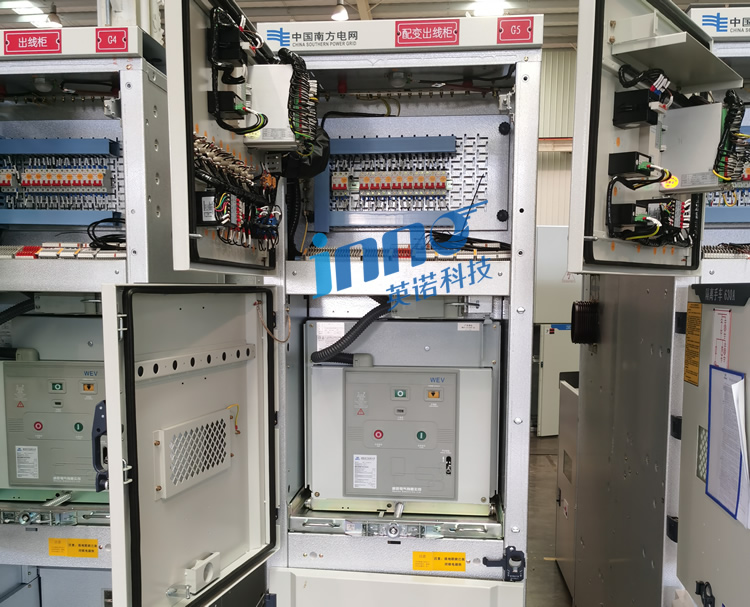
2. 高電圧開閉装置のどの重要なポイントで温度監視が必要か?
Identifying the most vulnerable thermal points ensures monitoring resources focus on locations where failures most frequently originate and cause maximum operational impact.
2.1 Why Are Busbar Connection Points the Most Vulnerable Thermal Weak Points?
バスバー接続 experience the highest electrical current densities and mechanical stress from thermal cycling, making them prime locations for resistance increases. Bolted connections can loosen over time due to vibration and thermal expansion, creating micro-gaps that generate excessive heat. Temperature sensors should monitor each phase at main busbar joints, especially connections between different conductor materials or where busbar sections transition.
2.2 How Does Circuit Breaker Contact Temperature Monitoring Prevent Poor Contact Conditions?
Circuit breaker contact degradation develops gradually through arcing erosion and contact surface oxidation. 監視 サーキットブレーカーの端子 provides early warning before contact resistance reaches levels that impair breaking capacity or cause welding. Temperature differentials between phases often indicate uneven contact pressure requiring mechanical adjustment before failure occurs.
2.3 What Warning Signals Indicate Abnormal Cable Termination Temperature Rise?
ケーブル終端 fail when insulation degrades from sustained elevated temperatures or when crimp connections loosen. Warning signals include temperature increases of 10°C or more above ambient within short periods, temperatures exceeding manufacturer specifications (typically 70-90°C), or significant phase-to-phase temperature imbalances exceeding 15°C that suggest connection quality differences.
2.4 How Does Disconnect Switch Blade Contact Temperature Affect Power Supply Reliability?
Disconnect switch blade contacts oxidize and lose spring tension over operational years, increasing contact resistance. 監視 スイッチの接点を切断する prevents failures that typically occur during switching operations when degraded contacts arc and weld. Temperature trending identifies deteriorating switches before they fail during critical load transfers or emergency switching procedures.
3. どうやって 蛍光ファイバー光温度センサー Solve High Voltage Measurement Challenges?
Traditional metal-based temperature sensors cannot operate safely in high voltage environments, creating the need for specialized measurement technologies that function reliably while maintaining electrical isolation.
3.1 Why Can’t Metal Sensors Be Used in High Voltage Strong Electric Field Environments?
従来の熱電対と RTD には、高電圧コンポーネントからグランドまでの電気経路を形成する導電性要素が含まれています。, 危険な故障電流や測定誤差を引き起こす. 金属センサーも電磁干渉を受け、強電界では温度測定値が 10 ~ 50°C 低下します。. 光ファイバー温度センサー 無限の電気抵抗を維持する完全誘電体構造により、これらの問題を解決します。.
3.2 光ファイバー温度センサーの電磁干渉耐性はどの程度強いか?
蛍光光ファイバーセンサー 電流ではなく光信号を通じて温度情報を送信します。, 電磁場に対する完全な耐性を提供します。 100 電子センサーを飽和させる kV/m. This immunity ensures accurate measurements adjacent to busbars carrying thousands of amperes and in switchgear experiencing switching transients exceeding 10 kV/μs. Independent testing confirms measurement accuracy remains within ±1°C regardless of electromagnetic environment.
3.3 How Does ±1°C Measurement Accuracy Meet Switchgear Monitoring Requirements?
Thermal fault progression typically involves temperature increases of 20-40°C above normal operating levels before failure occurs. の ±1°C accuracy specification provides sufficient resolution to detect developing faults at early stages while filtering normal temperature fluctuations from load variations. This precision enables trending analysis that identifies gradual resistance increases over weeks or months before they become critical.
3.4 How Does All-Dielectric Construction Achieve Intrinsic Safety and Long-Term Stability?
The completely non-metallic construction of 蛍光ファイバーセンサー eliminates potential ignition sources in hazardous environments and prevents galvanic corrosion that degrades sensor accuracy over time. Glass fiber and ceramic phosphor sensing elements maintain calibration stability within ±0.5°C over 10+ year service periods, eliminating recalibration requirements that add maintenance costs with electronic sensors.
4. さまざまな電圧レベルの温度監視ソリューションの違いは何ですか?
Monitoring system design must account for voltage class specific considerations including insulation coordination, safety clearances, and typical failure mechanisms that vary across distribution voltage levels.
4.1 Which Temperature Points Need Monitoring in 10kV Medium Voltage Switchgear?
標準 10kV switchgear monitoring configurations include 3-6 ベイあたりのセンサー数: three sensors on main busbar phase connections, two sensors on circuit breaker line-side terminals, and one sensor on cable termination. Indoor metal-clad switchgear benefits from additional sensors on load-side connections and transformer primary terminals where current concentration increases thermal stress.
4.2 How to Design Temperature Monitoring Solutions for 35kV Distribution Equipment?
35kV switchgear systems require extended safety clearances and typically employ gas-insulated or air-insulated designs with larger conductor spacing. Monitoring priorities include outdoor disconnect switches exposed to environmental temperature variations, transformer bushings experiencing combined electrical and thermal stress, and main busbar sections in three-phase enclosures. Sensor quantities typically range from 6-12 per bay depending on configuration complexity.
4.3 What Special Monitoring Requirements Exist for 110kV and Higher Voltage Equipment?
Transmission voltage 110kV+ switchgear introduces challenges including physical scale requiring fiber optic cable runs exceeding 50 メートル, outdoor installations requiring weatherproof sensor housings rated for UV exposure and -40°C to +80°C ambient temperatures, and retrofit installations on energized equipment requiring specialized safety procedures. Monitoring systems must integrate with SCADA infrastructure and provide redundant communication paths for high-reliability applications.
4.4 Does Low Voltage Distribution Equipment (400V) Need Fiber Optic Temperature Monitoring?
その間 400V low voltage switchgear permits electronic sensor use, fiber optic monitoring offers advantages in high-current applications (>1000あ), locations with severe electromagnetic interference from VFDs or welding equipment, and facilities requiring intrinsically safe installations near flammable materials. Cost considerations typically favor electronic sensors for standard low-voltage applications unless special conditions exist.
5. 適切なマルチチャネル温度監視システム構成を選択する方法?

Right-sizing monitoring channel capacity optimizes initial investment while providing expansion capability as facility monitoring needs grow or as additional critical equipment is added to monitoring coverage.
5.1 How Many Temperature Monitoring Channels Does a Single Switchgear Bay Require?
典型的な switchgear bay monitoring 必要 4-8 チャンネル: three channels for three-phase main busbar connections, 1-2 channels for circuit breaker terminals, 1-2 channels for cable terminations, and optional channels for auxiliary connections or transformer terminals. High-current applications (>2000あ) or critical loads may warrant doubled monitoring with redundant sensors on key points.
5.2 どうやって 1-64 Channel Systems Match Different Substation Scales?
Small commercial facilities typically deploy 4-8 チャネル 監視システム covering single switchgear lineups. Industrial substations with 3-6 switchgear bays utilize 16-32 チャネル構成. Large utility substations or data center electrical distribution systems require 32-64 channel platforms to monitor multiple voltage levels and redundant power paths. Modular system architectures allow incremental expansion from initial installations to full facility coverage over time.
5.3 What Factors Determine Fiber Optic Probe Diameter and Length Customization?
光ファイバープローブの直径 selection balances mechanical flexibility for installation routing versus durability for high-vibration environments. Standard 2mm diameter probes suit most applications, 1mm プローブはケーブルグランドを介した厳密な配線に対応します, 3mm プローブにより、屋外または振動の多い場所での耐久性が向上します。. プローブの長さのカスタマイズにより、監視ポイントから開閉装置のケーブル入口までのケーブル配線距離が考慮されます。, 通常は~の範囲です 1-5 屋外設置用に長いカスタム長のメートルも利用可能.
5.4 -40°C ~ 260°C の温度測定範囲はどのようなアプリケーション シナリオをカバーしますか?
の -40℃~260℃の範囲 ローエンドでの北極圏の屋外設置やハイエンドでの断熱温度限界に近づく障害状態などの極端な環境条件に対応します。. 通常の開閉装置は 20 ~ 90 °C で動作し、警報しきい値は 90 ~ 120 °C、緊急しきい値は 120 ~ 150 °C に設定されます。. The extended range provides safety margin and enables sensor reuse across different applications from refrigerated facilities to industrial furnace electrical feeds.
6. 開閉装置温度監視システムを設置するための重要な実装ポイントは何ですか?
Proper installation techniques ensure accurate measurements, 長期的な信頼性, and compliance with electrical safety standards while minimizing impact on existing equipment operation.
6.1 How to Correctly Mount Fiber Optic Probes on Energized Busbars?
Fiber probe installation on energized busbars requires specialized mounting hardware that maintains thermal contact while preserving electrical isolation. Spring-loaded clips or adhesive-backed mounting pads with thermal interface material ensure consistent thermal coupling. Probe tips should contact flat busbar surfaces cleaned of oxidation, with sensor orientation perpendicular to current flow to minimize electromagnetic field effects on fiber routing. All mounting hardware must be rated for operating voltage and temperature.
6.2 What Sealing Considerations Are Important When Routing Fiber Through Cabinet Walls and Barriers?
Cable entry through switchgear enclosures must maintain IP protection ratings (typically IP54-IP65) and prevent moisture ingress while allowing fiber routing without excessive bending stress. Specialized fiber optic cable glands with silicone or EPDM seals accommodate small fiber diameters while providing environmental sealing. Entry points should avoid sharp edges that could damage fiber jackets, and routing should maintain minimum bend radius (typically 10x cable diameter) to prevent optical signal loss.
6.3 Can Fluorescent Fiber Optic Sensors Be Installed on Energized Equipment Without Power Interruption?
全誘電体構造 蛍光ファイバーセンサー permits live installation using appropriate safety procedures and personal protective equipment. Installation on energized equipment follows hot-work permitting requirements with qualified electrical workers maintaining appropriate clearance distances for voltage class. Sensor mounting hardware installation typically requires 10-30 minutes per point with proper tools and preparation, enabling monitoring system deployment without outage costs.
6.4 Where Should Temperature Transmitters Be Located for Optimal Performance?
Temperature monitoring transmitters should mount in climate-controlled environments within 100 meters of fiber optic probes for standard installations, with longer distances requiring optical budget calculations. コントロールルームまたはリレーパネルの取り付けにより安定した周囲温度を提供 (15-30℃) 試運転とメンテナンスのためのアクセス. 送信機の設置場所は、データ統合のための通信インフラへのアクセスと、適切な回路保護を備えた電源の利用可能性を考慮する必要があります。.
7. 温度データを配電自動化システムと統合する方法?

監視制御システムとのシームレスな統合により集中監視が可能, 自動アラーム処理, 包括的な資産管理のための熱状態と電気負荷プロファイルの相関関係.
7.1 SCADA システム統合でサポートされる通信プロトコル?
モダンな 温度監視システム Modbus RTU/TCP を提供, DNP3, IEC 61850, ユーティリティおよび産業用 SCADA 統合のための OPC UA プロトコルのサポート. イーサネット接続により、100Mbps 帯域幅による直接ネットワーク統合が可能になり、マルチチャネル データ送信が可能になります。. Protocols should be selected based on existing automation infrastructure with IEC 61850 preferred for new utility installations and Modbus TCP common in industrial facilities. Multiple simultaneous protocol support allows parallel integration with facility management systems and equipment-specific monitoring platforms.
7.2 How to Set Reasonable Temperature Alarm Thresholds and Staged Response Strategies?
効果的 アラームしきい値の設定 implements multi-stage escalation: Pre-alarm at 10-15°C above normal operating temperature for awareness, Warning alarm at manufacturer thermal class limits (typically 90-105°C) triggering increased monitoring, and Critical alarm at 120-130°C requiring immediate investigation. Threshold settings should account for ambient temperature variations, load cycling patterns, and equipment-specific manufacturer recommendations. Rate-of-rise alarms detecting 5°C increase within 15-30 minutes provide early fault detection before absolute thresholds are reached.
8. 実際のケーススタディ: 典型的な高電圧開閉装置の温度監視プロジェクトの分析
A large manufacturing facility implemented comprehensive monitoring on their 13.8kV distribution system serving critical production lines requiring 99.98% electrical availability. The installation included 48 蛍光 光ファイバー温度センサー monitoring six switchgear lineups with eight channels per lineup covering main busbars, サーキットブレーカー, and transformer connections.
Project Implementation Details
Sensors were installed during a planned outage using hot-stick mounting techniques on select energized sections under safety supervision. The system detected a developing fault on a circuit breaker line-side connection showing gradual temperature increase from 65°C to 95°C over three weeks. Temperature trending correlated with load patterns indicated loose connection rather than overload condition.
Results and Return on Investment
Planned maintenance during scheduled outage corrected the connection before failure occurred, avoiding estimated $280,000 in production losses from unplanned outage. Total monitoring system investment of $45,000 achieved payback in a single prevented failure while providing ongoing protection across the facility. Annual inspection costs reduced 40% by transitioning from quarterly thermal imaging to condition-based inspections triggered by monitoring data.
9. 温度監視を通じて予知保全を実現する方法?
Temperature trending transforms monitoring data into actionable maintenance insights that optimize resource allocation and extend equipment service life through timely interventions before failures develop.
Temperature Trend Analysis and Fault Prediction Methods
歴史的 気温の傾向 establishes equipment-specific baselines accounting for load variations and seasonal ambient changes. Statistical analysis identifies deviations exceeding three standard deviations from normal patterns, triggering investigations before alarm thresholds are reached. Trending periods should span multiple load cycles (通常 30-90 日) to differentiate normal variations from developing faults. Machine learning algorithms can analyze multi-point data to detect patterns indicating specific failure modes.
Correlation Between Load Current and Temperature for Connection Health Assessment
Thermal performance analysis correlates temperature rise versus load current to calculate effective connection resistance. Healthy connections show linear temperature-current relationships, while developing faults exhibit exponential temperature increases or phase imbalances under load. Periodic resistance calculations enable trending of degradation rates and remaining service life estimation for planned replacement before emergency failure.
10. 老舗メーカーのソリューションを選択するメリットは何ですか?
Selecting monitoring systems from experienced manufacturers ensures product reliability, テクニカルサポートの品質, and long-term availability of replacement parts critical for multi-decade switchgear service life.
Quality Standards and Certification Requirements
Reputable manufacturers provide products certified to IEC 61010 electrical safety standards, UL listings for North American installations, and CE marking for European markets. 温度監視システム should meet IEC 60255 for protective relay environments and IEEE standards for utility applications. Factory calibration certificates traceable to national standards ensure measurement accuracy verification.
Technical Support and Long-Term Service Capabilities
Established manufacturers offer engineering support during system design, commissioning assistance for complex installations, and technical service throughout product lifecycle. Access to application engineers familiar with utility and industrial requirements ensures optimal system configuration. Long-term parts availability and backward compatibility for system expansions protect monitoring infrastructure investments over 15-20 year operational horizons typical of electrical distribution equipment.
免責事項
専門家の取り付けが必要です: High voltage switchgear temperature monitoring system installation must be performed by qualified electrical personnel following all applicable electrical codes, 安全規格, そしてメーカー仕様書. This article provides general technical information and does not constitute professional engineering advice for specific installations.
安全上の警告: Working on or near energized high voltage equipment presents serious injury or death risks from electrical shock, アークフラッシュ, and other hazards. All work must follow NFPA 70E, OSHA regulations, and employer safety procedures with appropriate personal protective equipment and safety training.
No Warranty: Information presented represents general industry practices as of December 2025. 設備仕様, 標準, and recommended practices evolve over time. Readers should verify current requirements and consult with qualified engineers and equipment manufacturers for project-specific guidance. The author assumes no liability for actions taken based on this information.

光ファイバー温度センサー, インテリジェント監視システム, 中国の分散型光ファイバーメーカー
 |
 |
 |