 INNO faseroptische Temperatursensoren ,Temperaturüberwachungssysteme.
- Complete Electrical Insulation – Immune to high voltage environments up to 100kV+, ensuring operator safety and measurement accuracy
- Intrinsic EMI Immunity – Unaffected by strong electromagnetic fields common in switchgear environments
- Critical Contact Point Monitoring – Real-time temperature tracking of Kontakte des Leistungsschalters, Sammelschienenverbindungen, Und Kabelendverschlüsse
- Lange Lebensdauer – 20+ years maintenance-free operation with no battery replacement required
- Hohe Präzision – ±0.5-1°C accuracy for early fault detection
- Explosion-Proof Design – Passive optical sensing with no electrical components at measurement points
- Mehrpunktüberwachung – Einzelsender unterstützt 1-64 Kanäle für eine umfassende Berichterstattung
- Schnelle Reaktionszeit – Detects temperature anomalies within seconds to prevent equipment failure
- Einfache Integration – Compatible with SCADA systems via Modbus, IEC61850 protocols
- Cost-Effective Prevention – Reduces unplanned downtime and extends equipment lifespan
Quick Navigation
- Why Does High Voltage Switchgear Require Temperature Monitoring?
- Which Parts of Switchgear Are Prone to Overheating?
- Where Are Switchgear Temperature Monitoring Systems Applied?
- What Causes Temperature Anomalies in Switchgear?
- What Temperature Monitoring Technologies Are Available?
- Why Are Fluorescent Fiber Optic Sensors Best for Switchgear?
- How to Configure a Switchgear Monitoring System?
- What Are Real-World Global Applications?
- How to Select a Temperature Monitoring Supplier?
- Spitze 10 Globale Hersteller
- FAQ – Common Questions
- Get Your Customized Monitoring Solution
1. Why Does High Voltage Switchgear Require Temperature Monitoring?

Hochspannungsschaltanlage serves as the critical node in power distribution systems, controlling and protecting electrical equipment in substations, Industrieanlagen, and power generation plants. Zu den gängigen Typen gehören: KYN28, XGN, GCS switchgear, Und Ringhaupteinheiten (RMU). These systems operate under extreme electrical stress, where even minor contact resistance increases can trigger catastrophic failures.
Temperature anomalies in switchgear compartments represent the earliest indicator of impending failure. When electrical contacts deteriorate due to oxidation, mechanischer Verschleiß, or improper installation, contact resistance increases exponentially. This generates excessive heat that accelerates further degradation, creating a dangerous feedback loop.
Primary Causes of Switchgear Fires
Statistical analysis of switchgear incidents reveals that thermal failures account for over 65% of all catastrophic events. Traditional periodic inspections using Infrarot-Thermografie can only provide snapshots during scheduled maintenance windows, missing the critical temperature evolution between inspections.
Contact Overheating Mechanisms
The relationship between contact resistance and heat generation follows Joule’s law (P = I²R), meaning temperature rise accelerates quadratically with current load. A mere 10% increase in contact resistance can result in 21% more heat generation under full load conditions.
Verschlechterung der Sammelschienenverbindung
Sammelschienenverbindungen are particularly vulnerable due to thermal cycling, Vibration, und Oxidation. Loose bolting compounds this issue, as micro-movements create hot spots that traditional monitoring cannot detect until visible damage occurs.
2. Which Parts of Switchgear Are Prone to Overheating?

Understanding critical monitoring points is essential for effective thermal surveillance. Different components exhibit distinct thermal signatures based on their function and failure modes.
| Komponente | Failure Probability | Thermal Characteristics | Überwachungsherausforderung |
|---|---|---|---|
| Kontakte des Leistungsschalters | 60-70% | Schnelle Temperaturspitzen beim Schalten | Hochspannungsisolierung erforderlich |
| Sammelschienenverbindungen | 15-20% | Allmählicher Temperaturanstieg | Mehrere Verbindungspunkte |
| Trennkontakte | 10-15% | Lastabhängige Heizung | Bewegliche Kontaktflächen |
| Kabelanschlüsse | 8-12% | Konzentrierte Wärme an den Laschen | Platzbeschränkungen |
| Kontakte des Messerschalters | 5-8% | Ungleichmäßiger Anpressdruck | Einschränkungen der Zugänglichkeit |
Wärmespeicherung in Kontaktflächen
Elektrische Kontakte In Vakuum-Leistungsschalter Und SF6-Schaltanlage Bei jedem Vorgang kommt es zu mechanischer Erosion. Der Materialtransfer zwischen Kontakten führt zu Oberflächenunregelmäßigkeiten, die den Stromfluss auf kleinere Bereiche konzentrieren, exponentiell steigende lokale Temperaturen.
Fehler bei Schraubverbindungen
Schraubverbindungen der Sammelschienen lösen sich mit der Zeit aufgrund von thermischen Ausdehnungszyklen und Vibrationen. A 20% Eine Reduzierung des Drehmoments kann den Kontaktwiderstand verdoppeln, creating invisible hot spots that infrared cameras cannot penetrate through metallic enclosures.
3. Where Are Switchgear Temperature Monitoring Systems Applied?
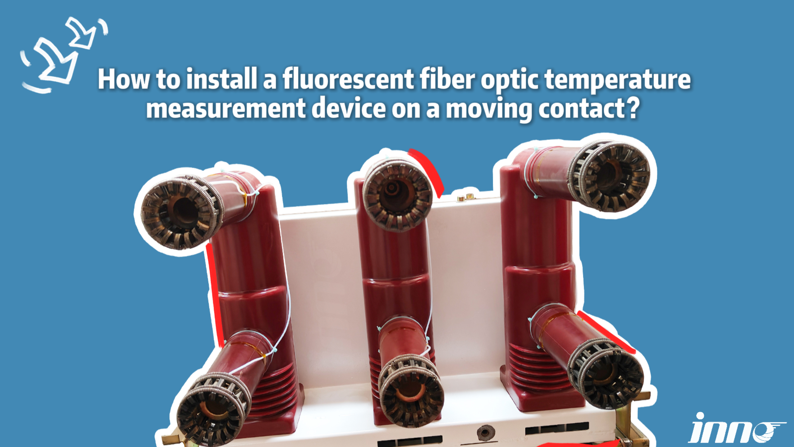
Temperaturüberwachungssysteme have become essential across diverse industries where power reliability is non-negotiable. Applications span from utility-scale infrastructure to mission-critical commercial facilities.
Power Generation Facilities: Main transformer high-voltage switchgear in coal, Gas, nuklear, and renewable energy plants require continuous monitoring due to the catastrophic consequences of unplanned outages.
Transmission & Distribution Substations: 110kV, 220kV, and 500kV GIS (Gasisolierte Schaltanlage) installations benefit from fiber optic monitoring that penetrates metallic enclosures without compromising insulation.
Industrial Manufacturing Plants
10kV and 35kV distribution switchgear in steel mills, Chemieanlagen, and automotive factories face harsh environments with corrosive atmospheres and heavy vibration that accelerate contact degradation.
Data Center Critical Power Systems
Dual-feed Mittelspannungsschaltanlage serving server farms demands 99.999% Verfügbarkeit. Fluoreszierende faseroptische Sensoren provide redundant monitoring without introducing potential ignition sources in battery rooms.
Rail Transportation Networks: Traction substations for metro, light rail, and high-speed rail systems experience frequent switching operations that rapidly degrade contacts. Continuous monitoring extends maintenance intervals while ensuring passenger safety.
Petrochemie & Offshore Platforms: Explosion-proof requirements and extreme environmental conditions make passive faseroptische Temperaturerfassung the only viable long-term solution for offshore oil rigs and LNG terminals.
4. What Causes Temperature Anomalies in Switchgear?
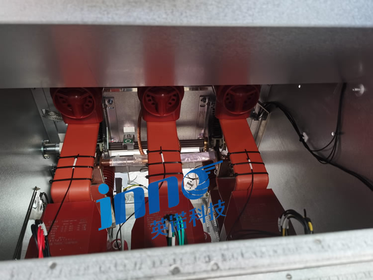
Understanding root causes enables predictive maintenance strategies that address problems before they escalate into failures. Thermal anomalies rarely occur suddenly; they represent the culmination of progressive degradation processes.
Contact Oxidation and Mechanical Wear (45% of Incidents)
Silver-plated copper contacts form insulating oxide layers when exposed to oxygen and sulfur compounds. This increases contact resistance by orders of magnitude, generating localized hot spots that further accelerate oxidation in a destructive cycle.
Insufficient Bolt Torque in Connections
Installation errors and maintenance oversights result in under-torqued Sammelschienenverbindungen. Industry standards specify precise torque values, yet field measurements reveal 30-40% of bolted joints fall below specifications, creating latent thermal hazards.
The Vicious Cycle of Resistance Increase
As contact resistance grows, heat generation increases proportionally to I²R. This heat softens copper alloys, reducing contact pressure and further increasing resistance. Ohne Eingriff, this feedback loop leads to arcing, welding, or complete joint failure.
Load Current and Temperature Squared Relationship
Doubling the load current quadruples the heat generation at resistive connections. Schaltanlage operating at 80% capacity may show acceptable temperatures, but brief overloads can trigger thermal runaway in degraded contacts.
Environmental Factors: Umgebungstemperatur, ventilation blockages, and seasonal variations affect the thermal baseline. Temperaturüberwachungssysteme must compensate for these factors to accurately detect abnormal trends.
Aging and Insulation Degradation: Epoxy resin insulators and polymeric components degrade over decades, sometimes creating tracking paths that generate parasitic currents and additional heating.
5. What Temperature Monitoring Technologies Are Available?
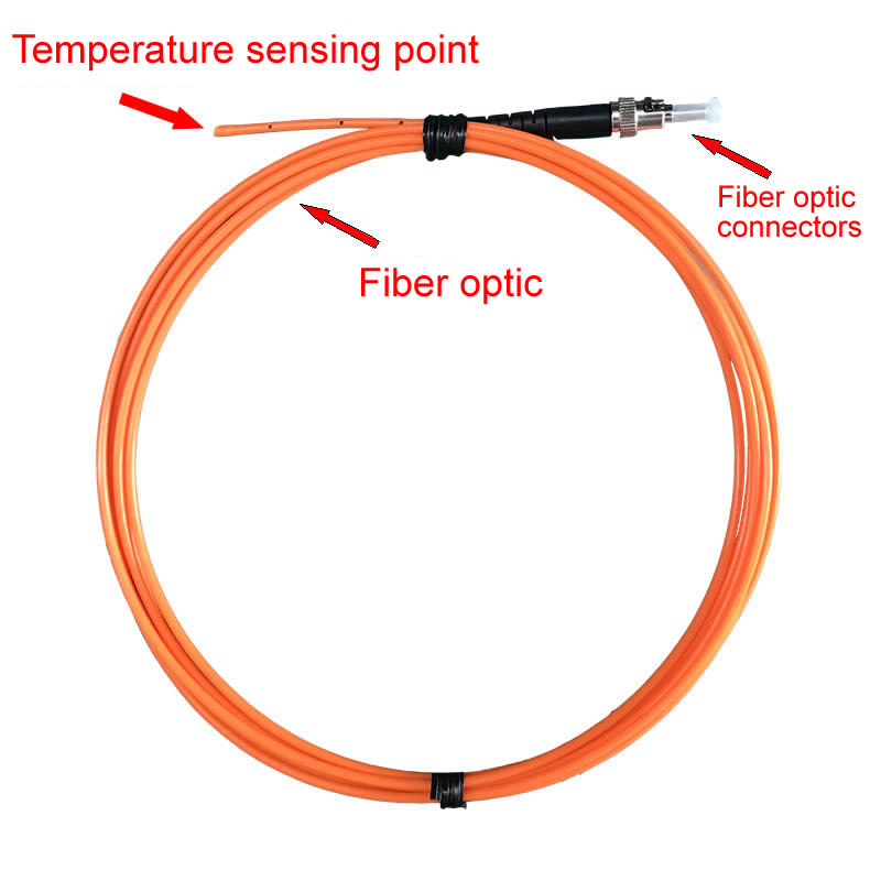
Multiple technologies compete in the Schaltanlagenüberwachung Markt, jeweils mit unterschiedlichen Vorteilen und Einschränkungen. Understanding these trade-offs is critical for selecting appropriate solutions.
| Technologie | Isolierung | EMI-Immunität | Genauigkeit | Lebensdauer | Eignung |
|---|---|---|---|---|---|
| Fluoreszierende Glasfaser | Vollständig | Gesamt | ±0,5-1°C | 20+ Jahre | Exzellent |
| Drahtlose Sensoren | Gut | Mäßig | ±1-2°C | 5-8 Jahre | Gut |
| Infrarot-Thermografie | Vollständig | N / A | ±2-5°C | Equipment-based | Beschränkt |
| FBG-Faser-Bragg-Gitter | Gut | Gut | ±1-2°C | 15+ Jahre | Mäßig |
| Thermoelemente | Erfordert Isolation | Arm | ±1-3°C | 10 Jahre | Arm |
Drahtlose Temperatursensoren offer installation convenience but suffer from battery dependency. Replacing batteries in energized high-voltage compartments requires costly outages and poses safety risks, making long-term total ownership costs prohibitive.
Infrarot-Wärmebildgebung provides valuable diagnostic information during periodic inspections but cannot deliver continuous monitoring. Thermal cameras cannot penetrate metallic enclosures, limiting their effectiveness for enclosed Schaltanlage Entwürfe.
Faser-Bragg-Gitter (FBG) Sensoren verwenden Wellenlängenmultiplex, um mehrere Punkte auf einer einzelnen Faser zu überwachen. Jedoch, Diese Architektur schafft Single Points of Failure – ein Faserbruch deaktiviert alle nachgeschalteten Sensoren. Auch die Wellenlängenstabilität nimmt mit der Zeit ab, eine regelmäßige Neukalibrierung erforderlich ist.
6. Warum sind Fluoreszierende faseroptische Sensoren Am besten für Schaltanlagen geeignet?
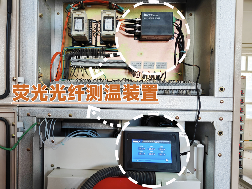
Fluoreszierende faseroptische Temperatursensoren Nutzen Sie die Quantenphysik, um in rauen elektrischen Umgebungen eine beispiellose Leistung zu erzielen. Im Gegensatz zu herkömmlichen Technologien, Sie messen die Temperatur durch den Abfall der Fluoreszenzlebensdauer, ein Parameter, der grundsätzlich immun gegen Signalamplitudenschwankungen ist.
Complete Electrical Insulation (>100kV-Beständigkeit)
Glasfasern enthalten keine metallischen Bestandteile, Bereitstellung eines unendlichen elektrischen Widerstands. Sensoren können direkt an unter Spannung stehende Sensoren geklebt werden Sammelschienenverbindungen Und Kontakte des Leistungsschalters ohne die Hochspannungsisolierung zu beeinträchtigen oder Erdschleifen einzuführen.
Intrinsische Immunität gegen elektromagnetische Störungen
Optical signals remain unaffected by the intense magnetic fields generated during fault conditions and switching transients. This immunity extends to radio frequency interference from nearby transmitters and arc flash events that destroy electronic sensors.
Quantum Physics of Fluorescence Lifetime Measurement
When UV light excites rare-earth phosphors in the Sensorsonde, electrons jump to higher energy states. As they return to ground state, they emit visible light with a decay time inversely proportional to absolute temperature. This relationship follows the Arrhenius equation, providing measurement stability over decades.
Dedicated Fiber Architecture vs. Multiplexed Systems
One-fiber-one-sensor architecture eliminates cascading failures. If a single fiber breaks, only that measurement point is affected—all other channels continue operating normally. This redundancy is impossible with wavelength-multiplexed or time-division systems where fiber breaks disable multiple sensors.
No Calibration Required: The temperature-decay time relationship is determined by fundamental physical constants, not electronic components that drift with age. Fluoreszierende Sensoren maintain factory calibration throughout their entire service life without field adjustments.
Leistung in rauen Umgebungen: Operating ranges from -200°C to +250°C accommodate extreme conditions. Sensors resist moisture, Chemikalien, Strahlung, and vibration that rapidly degrade electronic alternatives.
Modular Transmitter Design: Fiber optic transmitters scale from single-channel to 64-channel configurations, allowing systems to grow with monitoring requirements without replacing infrastructure. Hot-swappable channel modules enable repairs without system shutdown.
7. How to Configure a Switchgear Monitoring System?
Optimal system configuration balances comprehensive coverage with practical cost constraints. Strategic sensor placement maximizes failure detection probability while minimizing installation complexity.
| Application Scale | Überwachungspunkte | Recommended Channels | Typische Konfiguration |
|---|---|---|---|
| Single Switchgear Panel | 3-6 Punkte | 8-channel transmitter | Contacts×2 + Busbar×2 + Terminals×2 |
| Substation Feeder Bay | 12-18 Punkte | 32-channel transmitter | 2-3 panels complete coverage |
| Full Switchroom | 40-60 Punkte | 64-channel transmitter | 8-10 panels critical points |
Strategic Sensor Placement Principles
Priority monitoring points include all three-phase Kontakte des Leistungsschalters (both fixed and moving), main Sammelschienenverbindungen, and outgoing feeder connections. Secondary points cover disconnector blades, Erdungsschalter, and cable glands.
System Scalability Design
Fiber optic transmitters with modular architecture allow incremental expansion. Initial deployments can monitor the most critical circuits, with additional channels activated as budget permits or new equipment is commissioned.
Communication Interface Selection: Modern systems support Modbus RTU/TCP, IEC 61850, DNP3, Und PROFINET Protokolle, enabling integration with existing SCADA infrastructure, Gebäudemanagementsysteme, or standalone alarming panels.
8. What Are Real-World Global Applications?
Deployment experiences across continents demonstrate the universal applicability and proven reliability of Fluoreszenz-Glasfaserüberwachung in diverse operating environments.
European Utility Implementation – 400kV Substation Network
A major transmission operator across Central Europe retrofitted 150+ GIS-Umspannwerke with comprehensive monitoring covering over 8,000 Messpunkte. The system detected multiple developing faults in circuit breaker mechanisms that conventional maintenance would have missed, preventing multiple unplanned outages during peak demand periods.
Middle East Petrochemical Complex – Hazardous Area Monitoring
An integrated refinery and chemical plant in the Gulf region implemented explosion-proof faseroptische Temperaturerfassung über 220 switchgear panels in Zone 1 Gefahrenbereiche. The passive optical architecture eliminated ignition risks while providing 24/7 surveillance of critical motorische Kontrollzentren Und Verteilertafeln.
North American Data Center – Mission-Critical Power
A hyperscale cloud computing facility deployed 64-channel monitoring across dual-fed Mittelspannungsschaltanlage serving 50MW of IT load. Continuous thermal surveillance enabled condition-based maintenance scheduling that reduced planned outage windows while maintaining five-nines availability targets.
Asian Metro System – Traction Power Monitoring
A metropolitan rail network installed monitoring across 80+ traction substations feeding 1500VDC overhead catenary. The system’s ability to track Kontakt des Leistungsschalters wear enabled predictive replacement before failures, improving on-time performance and passenger safety metrics.
Australian Mining Operation – Remote Location Reliability
An open-pit mine’s primary 33kV distribution switchgear serving draglines and conveyors operates in extreme heat and dust. Faseroptische Sensoren withstand temperatures exceeding 50°C ambient while providing early warning of connection degradation that would strand critical mining equipment.
9. How to Select a Temperature Monitoring Supplier?
Choosing the right technology partner extends beyond product specifications to encompass long-term support capabilities and proven track records in demanding applications.
Product Certifications and Testing: Verify compliance with IEC 61000 EMC standards, IEC 60255 protection relay specifications, and relevant electrical safety approvals for your region. Independently witnessed high-voltage withstand testing provides objective performance validation.
Critical Technical Parameter Evaluation
Scrutinize measurement accuracy across the full operating temperature range, not just at calibration points. Response time specifications should reflect real-world installation conditions including thermal contact resistance and sensor mounting methods.
Long-Term Support Value
Assess the manufacturer’s application engineering support, Inbetriebnahmeunterstützung, and spare parts availability. Global service networks become critical for international projects requiring local technical resources and rapid response capabilities.
System Integration Capability: Evaluate software platforms for data visualization, Trendanalyse, und Alarmmanagement. Die Unterstützung offener Protokolle ermöglicht die Integration in die vorhandene Infrastruktur ohne Anbieterbindung.
Nachgewiesene Anwendungserfahrung: Fordern Sie Referenzinstallationen in ähnlichen Branchen und Betriebsumgebungen an. Besuche vor Ort bei betrieblichen Einsätzen liefern Einblicke, die Produktdatenblätter nicht vermitteln können.
10. Spitze 10 Globale Hersteller
🏆 #1 Gerankter Hersteller
🥈 #2 Gerankter Hersteller
🌍 #3-10 International Manufacturers
3. Weidmann Elektrotechnik AG (Schweiz)
Gegründet: 1877 | Spezialisierung: High-voltage insulation systems and fiber optic monitoring solutions für Leistungstransformatoren Und Schaltanlage. Product portfolio includes Buchsenmonitore, Temperatursensoren, and dissolved gas analysis systems.
4. Qualitrol Company LLC (Vereinigte Staaten)
Gegründet: 1945 | Spezialisierung: Monitoring and protection systems for electrical assets. Angebote faseroptische Temperaturüberwachung für Transformatoren, Schaltanlage, Und Generatoren, alongside oil quality sensors and thermal relays.
5. LIOS Technology GmbH (Deutschland)
Gegründet: 1999 | Spezialisierung: Präzision faseroptische Temperaturmessung verwenden fluorescence lifetime technology. Applications include medical MRI systems, Leistungselektronik, Und high-voltage equipment monitoring.
6. Neoptix Inc. – Qualitrol (Kanada)
Gegründet: 2003 | Spezialisierung: Immun gegen elektromagnetische Störungen faseroptische Sensoren. Product range covers switchgear contact monitoring, cable joint temperature sensing, Und rotating machinery surveillance.
7. Omega Engineering Inc. (Vereinigte Staaten)
Gegründet: 1962 | Spezialisierung: Comprehensive measurement and control solutions including fiber optic thermometry, industriell temperature transmitters, and data acquisition systems for electrical equipment monitoring.
8. Yokogawa Electric Corporation (Japan)
Gegründet: 1915 | Spezialisierung: Industrial automation and test equipment including optical fiber temperature systems für Kraftwerke, Umspannwerke, and manufacturing facilities. Known for high-reliability monitoring platforms.
9. Micronor Inc. (Vereinigte Staaten)
Gegründet: 1985 | Spezialisierung: Harsh environment faseroptische Sensoren for aerospace, Verteidigung, und industrielle Anwendungen. Products include high-temperature probes, pressure transducers, Und EMI-immune measurement systems.
10. FISO Technologies Inc. (Kanada)
Gegründet: 1994 | Spezialisierung: Fortschrittlich faseroptische Sensorlösungen for medical, industriell, and research applications. Angebote miniature temperature sensors, Mehrpunkt-Überwachungssysteme, and custom OEM sensor development.
11. FAQ – Common Questions
What is the normal temperature range for high voltage switchgear?
Healthy Schaltgerätekontakte typically operate 10-30°C above ambient temperature under rated load. Temperatures exceeding 70°C warrant investigation, while readings above 90°C indicate imminent failure requiring immediate intervention. IEC 60694 standards specify maximum permissible temperature rises for different connection types.
How many monitoring points can one system handle?
Fluorescent fiber optic transmitters scale from single-channel to 64-channel configurations. Each channel independently monitors one temperature point. Larger installations utilize multiple transmitters networked via Modbus oder IEC 61850 protocols to provide comprehensive coverage across entire substations.
How are sensors installed on energized high-voltage components?
Temperature probes attach to energized surfaces using specialized thermal interface compounds during planned outages. The complete electrical insulation of optical fibers eliminates any compromise to system voltage withstand capability. Für die Installation sind in der Regel Standardverfahren zur elektrischen Sicherheit ohne spezielle Genehmigungen für Hochspannungsarbeiten erforderlich.
Welche Ausfalldauer ist für die Installation erforderlich??
Die typische Einzelpanel-Installation wird innerhalb der Standardwartungsfenster abgeschlossen. Sensorbefestigung und Glasfaserkabel Routing erfordern eine Abschaltung der Ausrüstung, Während der Montage und Inbetriebnahme des Senders müssen benachbarte Stromkreise unter Spannung stehen, Minimierung der Auswirkungen auf das System.
Beeinflusst ein Faserbruch andere Messkanäle??
NEIN. Die Architektur mit einer Faser pro Sensor gewährleistet vollständige Kanalunabhängigkeit. Person Glasfaserkabel Der Schaden betrifft nur diesen spezifischen Messpunkt, während alle anderen Kanäle den Normalbetrieb fortsetzen – ein entscheidender Vorteil gegenüber Multiplex-Systemen, bei denen einzelne Ausfälle kaskadiert werden.
Kann das System in die bestehende SCADA-Infrastruktur integriert werden??
Ja. Modern Glasfasersender provide industry-standard communication protocols including Modbus RTU/TCP, DNP3, IEC 61850, Und OPC UA, enabling seamless integration with utility SCADA systems, building management platforms, or standalone alarm panels without custom programming.
How to distinguish normal load-induced heating from fault conditions?
Monitoring software tracks temperature trends relative to load current profiles. Normal thermal response follows predictable patterns, while contact degradation manifests as progressive temperature elevation disproportionate to load changes. Asymmetry between three-phase measurements also indicates localized faults.
What is the expected equipment lifespan?
Fluoreszierende faseroptische Sensoren zeigen 20+ year operational life without degradation. Transmitter electronics typically carry 10-year warranties with modular designs enabling component-level repairs rather than complete system replacement, minimizing long-term ownership costs.
Is outdoor switchgear monitoring feasible?
Absolut. Glasfasersysteme excel in outdoor environments where moisture, UV exposure, and temperature extremes rapidly degrade electronic alternatives. IP65-rated transmitters and weatherproof sensor housings enable reliable operation from arctic to tropical climates.
What advantages exist versus wireless temperature sensors?
Fluoreszierende Glasfasertechnologie eliminates battery replacement—the Achilles heel of wireless monitoring. Zero EMI susceptibility, superior accuracy, longer lifespan, and no regulatory concerns about RF emissions in sensitive environments make optical sensing the preferred choice for critical infrastructure.
Can legacy switchgear be retrofitted with monitoring systems?
Ja. Temperaturüberwachung retrofits extend the safe operating life of aging Schaltanlage by providing visibility into degradation processes. Non-invasive sensor installation preserves original equipment warranties while adding modern diagnostic capabilities to decades-old installations.
12. Get Your Customized Monitoring Solution
🌐 Global Fluorescent Fiber Optic Temperature Solutions
We Provide:
- Fluorescent Fiber Optic Temperature Products – Complete sensor and transmitter systems
- Turnkey Solutions – Application engineering and system design
- Remote Commissioning Support – Virtual startup assistance and troubleshooting
- Worldwide Fast Shipping – Express logistics to all continents
- OEM/ODM-Anpassung – Private label and bespoke engineering services
📧 E-Mail: web@fjinno.net
📱 WhatsApp: +86 13599070393
💬 WeChat: +86 13599070393
Contact our switchgear monitoring specialists today for technical consultation and quotation
⚠️ Haftungsausschluss
The information provided in this article is for general educational purposes regarding Temperaturüberwachungstechnologien für Hochspannungsschaltanlagen. Dabei streben wir nach Genauigkeit, Spezifikationen des elektrischen Systems, Sicherheitsanforderungen, und regulatorische Standards variieren je nach Region und Anwendung. Konsultieren Sie immer qualifizierte Elektrotechniker und befolgen Sie die örtlichen Vorschriften und Anforderungen der Versorgungsunternehmen, bevor Sie Überwachungssysteme implementieren. Temperaturschwellen, Installationsverfahren, und Wartungspläne sollten auf der Grundlage von Herstellerempfehlungen und standortspezifischen Bedingungen festgelegt werden. Autor und Herausgeber übernehmen keine Haftung für Handlungen, die auf Grundlage dieser Informationen erfolgen. Produktspezifikationen und Unternehmensdetails können ohne vorherige Ankündigung geändert werden.

Faseroptischer Temperatursensor, Intelligentes Überwachungssystem, Verteilter Glasfaserhersteller in China
 |
 |
 |