 INNO faseroptische Temperatursensoren ,Temperaturüberwachungssysteme.
- Transformer winding temperature is the most critical parameter affecting insulation life and operational safety.
- Traditionelle Methoden wie z Öltemperaturanzeigen (ERLEDIGT), Wicklungstemperaturanzeigen (WTI), Und RTD-/Thermoelement-Sensoren each have inherent limitations in accuracy and direct measurement capability.
- Fluoreszierende faseroptische Temperaturüberwachungssysteme basierend auf GaAs-Sensortechnologie bieten direkte, Echtzeit, and high-voltage-immune winding temperature measurement.
- Eine Single faseroptischer Temperaturdemodulator unterstützt 1–64 Kanäle, RS485-Kommunikation, und vorbei 25 Jahre Lebensdauer.
- Dieser Artikel enthält eine vollständige Vergleichstabelle, globale Anwendungsfälle, and expert guidance for selecting the right monitoring solution.
Inhaltsverzeichnis
- Was ist die Wicklungstemperatur des Transformators??
- Causes and Hazards of Winding Temperature Rise
- International Standards and Temperature Limits
- Traditional Method: Öltemperaturanzeige (ERLEDIGT)
- Traditional Method: Wicklungstemperaturanzeige (WTI)
- Traditional Method: Thermocouple and RTD Sensors
- Empfohlen: Fluoreszierendes faseroptisches Temperaturüberwachungssystem
- Technical Comparison of All Four Methods
- Globale Anwendungsfälle
- Winding Temperature Protection and Control Logic
- Erhalten Sie eine maßgeschneiderte Lösung
- Häufig gestellte Fragen (FAQ)
- Haftungsausschluss
1. Was ist die Wicklungstemperatur des Transformators??

Transformer winding temperature refers to the actual thermal condition of the copper or aluminum conductors inside a power transformer. Among all measurable parameters — including Öltemperatur, Gehalt an gelöstem Gas, and load current — the winding hot-spot temperature is universally recognized as the single most important factor determining transformer health and remaining insulation life.
When a transformer carries load, current flowing through the windings produces resistive losses (I²R-Verluste) and eddy current losses, both generating heat. This heat accumulates in the winding conductors and must be dissipated through the insulating oil and cooling system. The point within the winding structure that reaches the highest temperature is known as the kurviger Hotspot. Accurately monitoring this hot-spot temperature is essential for safe loading decisions, thermal protection, and long-term asset management.
2. Causes and Hazards of Winding Temperature Rise
2.1 Primary Causes
Winding temperature rise is driven by several factors. Load current is the dominant contributor — as current increases, I²R losses increase proportionally with the square of the current. Eddy current and stray losses in the conductors and structural components generate additional heat. Ambient temperature and solar radiation directly affect the transformer’s ability to reject heat. Zusätzlich, degraded cooling systems — such as blocked radiators, failed fans, or deteriorated oil — reduce heat dissipation capacity and cause elevated winding temperatures.
2.2 Hazards of Excessive Winding Temperature
Excessive winding temperature accelerates the thermal degradation of cellulose insulation. According to the well-established Arrhenius aging model referenced in IEEE Std C57.91, the rate of insulation aging approximately doubles for every 6–7°C increase above the rated hot-spot temperature. Sustained overheating leads to reduced dielectric strength, formation of combustible gases, eventual insulation failure, and potentially catastrophic transformer damage. Reliable winding temperature monitoring is therefore not optional — it is a fundamental requirement for transformer protection.
3. International Standards and Temperature Limits
Several international standards govern transformer winding temperature limits and monitoring requirements. IEC 60076-2 specifies that the average winding temperature rise shall not exceed 65K above ambient for oil-immersed transformers, mit einer Hot-Spot-Temperaturanstiegsgrenze von 78 K. IEEE Std C57.12.00 similarly defines a 65°C average winding rise for most classes. IEEE Std C57.91 Bietet detaillierte Richtlinien zur thermischen Belastung, Hot-Spot-Berechnungsmethoden, und Isolationsalterungsgleichungen. IEC 60354 (now absorbed into IEC 60076-7) offers loading guidance based on thermal modeling. In diesen Normen wird gemeinsam festgelegt, dass die Hotspot-Temperaturen in kontinuierlichen Wicklungen für eine normale Lebenserwartung im Allgemeinen unter 110–120 °C bleiben sollten, with the maximum permissible value depending on the insulation class and loading duration.
4. Traditional Method: Öltemperaturanzeige (ERLEDIGT)
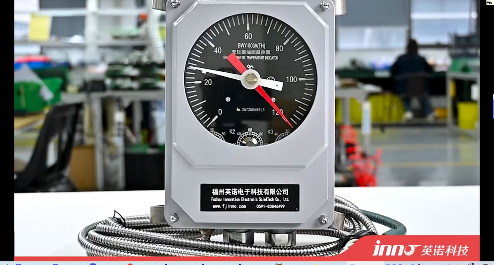
4.1 Funktionsprinzip
Ein Öltemperaturanzeige (ERLEDIGT), also commonly referred to as an Ölthermometer oder oil temperature gauge, measures the temperature of the insulating oil at or near the top of the transformer tank. The most common type uses a liquid-expansion (mercury or organic-filled) capillary system. A sensing bulb is inserted into a thermometer pocket welded on the transformer tank. As the oil temperature changes, the liquid in the bulb expands or contracts, driving a pointer on the dial gauge via the capillary tube.
4.2 Typical Parameters
Standard ERLEDIGT devices offer a measurement range of 0–150°C, with an accuracy of approximately ±3–5°C. They typically include adjustable alarm and trip contacts (Die Oberöltemperatur wird üblicherweise auf 85 °C und 95 °C eingestellt). Die Kapillarlänge ist in der Regel unter erhältlich 1 m zu 20 M. Die Reaktionszeit ist relativ langsam, typischerweise im Bereich von mehreren Minuten.
4.3 Einschränkungen
Der Öltemperaturanzeige Misst nur die Oberöltemperatur, was nicht direkt die Hot-Spot-Temperatur der Wicklung darstellt. Der tatsächliche Wicklungs-Hotspot kann 20–40 °C höher sein als die gemessene Öltemperatur. Mechanische Komponenten unterliegen im Laufe der Zeit einer Drift und Alterung, und das Gerät lässt sich ohne zusätzliche Signalwandler nicht einfach in moderne digitale Überwachungssysteme integrieren.
5. Traditional Method: Wicklungstemperaturanzeige (WTI)
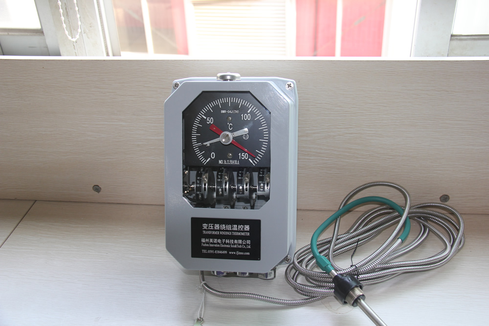
5.1 Funktionsprinzip
A Wicklungstemperaturanzeige (WTI) nutzt eine Wärmebildkamera (Simulation) Methode zur Schätzung der Hot-Spot-Temperatur der Wicklung ohne direkte Messung des Wicklungsleiters. Ein Stromwandler (CT) an der Buchse liefert ein Signal proportional zum Laststrom. This signal feeds a small heating element coiled around the sensing bulb of a thermometer pocket. The combination of the ambient oil temperature and the thermal contribution from the heating resistor simulates the thermal gradient between the oil and the winding, producing an indirect estimate of the winding hot-spot temperature.
5.2 Calibration and Setup
During factory heat-run testing, Die WTI is calibrated by adjusting the heating resistor current to match the measured winding-to-oil gradient at rated load. This calibration is specific to one loading condition. In the field, the relationship between load current and actual temperature gradient may deviate from the factory setting due to varying cooling conditions, oil aging, and non-linear thermal dynamics.
5.3 Typical Parameters
Ein Standard Wicklungstemperaturanzeige provides a display range of 0–200°C with an accuracy of approximately ±3–5°C for the simulated value. It includes two to four adjustable contacts for fan start, pump start, Alarm, and trip functions. Response time is moderate, typically 5–15 minutes due to the thermal inertia of the simulation element.
5.4 Einschränkungen
Because the WTI relies on an indirect thermal model rather than a direct measurement, its reading is an approximation. Under transient loading conditions, overload events, or when cooling system performance changes, the WTI may significantly deviate from the actual winding temperature. It is also vulnerable to calibration drift over the transformer’s service life.
6. Traditional Method: Thermocouple and RTD Sensors
6.1 Funktionsprinzip
Thermoelementsensoren (typically Type T or Type K) generate a voltage proportional to the temperature difference between the sensing junction and a reference junction. Platinum resistance temperature detectors (Pt100 RTD) measure temperature by detecting the change in electrical resistance of a platinum element. Both types can be embedded within the transformer winding during manufacturing to provide direct temperature readings of the conductor.
6.2 Typical Parameters
A Pt100 RTD offers an accuracy of ±0.5–1.5°C across a range of −200°C to +600°C. Thermocouples provide accuracy of ±1–2.5°C. Response times vary from 1 Zu 10 seconds depending on the encapsulation. Both types require metallic lead wires routed from the winding interior out through the transformer structure.
6.3 Einschränkungen
The primary drawback of embedded thermocouples and RTDs is that metallic lead wires introduce a conductive path into the high-voltage environment of the transformer winding. This creates insulation coordination challenges and increases the risk of dielectric failure. Auch elektromagnetische Störungen durch das Magnetfeld des Transformators können die Signalintegrität beeinträchtigen. Zusätzlich, Diese Sensoren können typischerweise nur während der Herstellung installiert werden, was Nachrüstanwendungen erschwert.
7. Empfohlen: Fluoreszierendes faseroptisches Temperaturüberwachungssystem

7.1 Warum fluoreszierende Glasfasertechnologie empfohlen wird
Unter allen verfügbaren Methoden, Die fluoreszierendes faseroptisches Temperaturüberwachungssystem ist die einzige Technologie, die wirklich direkt liefert, Echtzeitmessung der Transformatorwicklungstemperatur mit vollständiger Immunität gegenüber elektromagnetischen Störungen. Im Gegensatz zu OTI und WTI, die auf indirekter Schätzung beruhen, und im Gegensatz zu metallischen Thermoelementen oder RTDs, die die Isolationsintegrität gefährden, fluoreszierende faseroptische Sensoren Verwenden Sie vollständig dielektrische optische Fasern, die von Natur aus isolierend sind und kein elektrisches Risiko in die Hochspannungswicklungsumgebung mit sich bringen.
7.2 GaAs-Fluoreszenzsensorprinzip
Der Fluoreszierender faseroptischer Temperatursensor operates based on the temperature-dependent fluorescence decay characteristics of a Galliumarsenid (GaAs) semiconductor crystal bonded to the tip of an optical fiber. When pulsed light from the faseroptischer Demodulator excites the GaAs crystal, it emits fluorescent light whose decay time varies predictably with temperature. The demodulator analyzes the decay curve to determine the precise temperature at the sensing point. This is a point-type measurement method, providing a discrete and accurate temperature value at each sensor location.
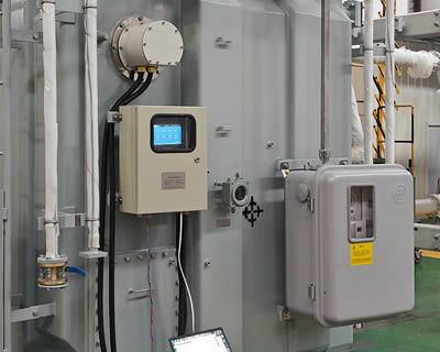
7.3 System Composition
Eine komplette fluoreszierendes faseroptisches Temperaturüberwachungssystem consists of five key components:
Fiber Optic Temperature Demodulator (Sender)

Der faseroptischer Temperaturdemodulator is the central processing unit of the system. It generates excitation light pulses, receives the returned fluorescent signal, and computes the temperature value. Ein einzelner Demodulator unterstützt 1 Zu 64 Messkanäle, making it suitable for monitoring multiple winding hot spots simultaneously. It provides an RS485-Kommunikationsschnittstelle (Modbus RTU) for integration with DCS, SCADA, or transformer monitoring IEDs. All channel configurations and communication parameters are customizable per project requirements.
Fluorescent Fiber Optic Cable

Der fluoreszierende Glasfaser cable transmits excitation and return light between the demodulator and the sensing probe. It is fully dielectric, oil-resistant, and designed for long-term immersion in transformer insulating oil. The cable length is available from 0 Zu 20 meters to accommodate various transformer sizes and routing requirements.
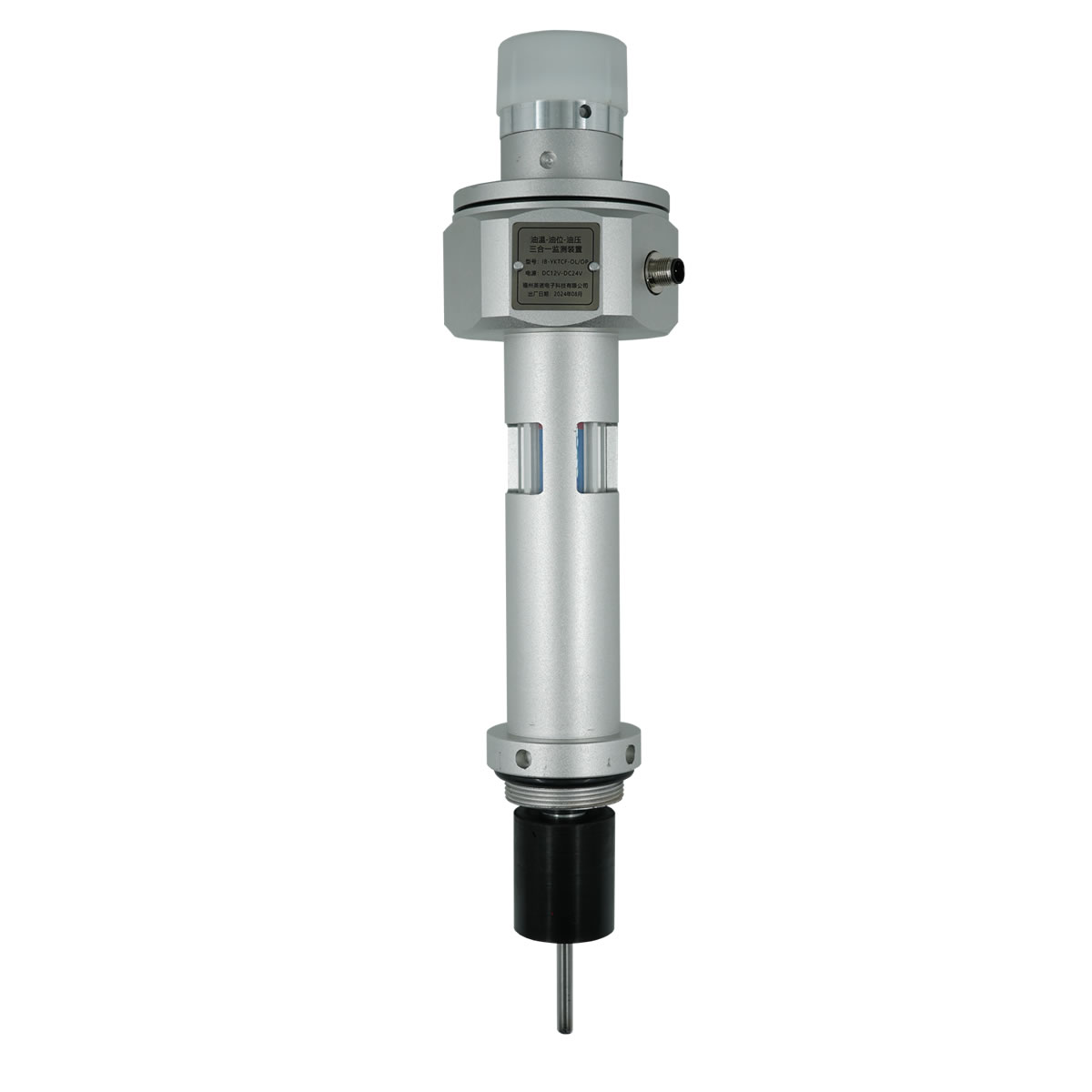
Sensing Probe
Der Fluoreszenz-Temperaturfühler enthält den GaAs-Kristall und ist der Ort der eigentlichen Temperaturmessung. The probe features a compact diameter of 2–3 mm and can be customized for specific installation requirements. It withstands continuous operating voltages exceeding 100 kV, Damit eignet es sich vollständig für die direkte Platzierung an Wicklungsleitern in Hochspannungs- und Höchstspannungstransformatoren.
Anzeigemodul
Der Temperaturanzeigemodul provides local visual indication of all channel readings, Alarmstatus, und Systemdiagnose. It is typically panel-mounted on the transformer control cabinet.
Überwachungssoftware
Der Temperaturüberwachungssoftware runs on a connected PC or server and provides real-time trending, historical data logging, Alarmmanagement, und Berichterstellung. It enables centralized remote monitoring of winding temperatures across multiple transformers.
7.4 Einbau in Transformatorwicklungen
Der fluoreszierende faseroptische Sensorsonde is installed during transformer manufacturing by embedding it directly at the calculated hot-spot location within the winding structure, typically between insulated conductors at the top of the high-voltage or low-voltage winding. Der Glasfaserkabel is routed through the insulation structure and exits the transformer through a dedicated fiber optic feedthrough fitting on the tank wall. Because the entire sensor is non-metallic and non-conductive, Es erfordert keine spezielle Isolationskoordination und stellt kein Risiko für die dielektrische Leistung des Transformators dar.
8. Technical Comparison of All Four Methods
The following table provides a comprehensive side-by-side comparison of all four transformer winding temperature monitoring methods discussed in this article.
| Parameter | ERLEDIGT (Öltemperaturanzeige) | WTI (Wicklungstemperaturanzeige) | Thermoelement / FTE | Fluoreszierende Glasfaser (GaAs) |
|---|---|---|---|---|
| Messtyp | Indirekt (Nur Öl) | Indirekt (thermal simulation) | Direkt (eingebettet) | Direkt (eingebettet) |
| Genauigkeit | ±3–5°C | ±3–5°C | ±0.5–2.5°C | ±0,5–1°C |
| Messbereich | 0–150°C | 0–200°C | −200 to +600°C | −40 to +260°C |
| Ansprechzeit | Several minutes | 5–15 minutes | 1–10 seconds | <1 zweite |
| EMI-Immunität | Mäßig | Mäßig | Arm | Vollständig (vollständig dielektrisch) |
| Spannungsfestigkeit | N / A (extern) | N / A (extern) | Beschränkt | >100 kV |
| Sondendurchmesser | Bulb type | Bulb type | 3–6 mm | 2–3 mm (anpassbar) |
| Sensormaterial | Metallisch | Metallisch | Metallisch | All-dielectric (insulating) |
| Cable/Fiber Length | 1–20 m | 1–20 m | Limited by signal loss | 0–20 m |
| Kanalkapazität | Einzel | Einzel | Mehrpunkt (verdrahtet) | 1–64 channels per demodulator |
| Kommunikation | Contacts only (analog) | Contacts only (analog) | Analog signal / 4–20 mA | RS485 (Modbus RTU), anpassbar |
| Lebensdauer | 10–15 Jahre | 10–15 Jahre | 10–20 Jahre | >25 Jahre |
| Nachrüstbarkeit | Einfach | Einfach | Difficult | Factory installation recommended |
| Relative Kosten | Niedrig | Niedrig–Mittel | Medium | Mittel–Hoch |
As shown in the table, Die fluoreszierendes faseroptisches Temperaturüberwachungssystem delivers the best combination of measurement accuracy, Reaktionsgeschwindigkeit, elektromagnetische Immunität, dielectric safety, and long service life — making it the clear choice for critical power transformers where reliable winding temperature data is essential.
9. Globale Anwendungsfälle

Fluorescent fiber optic winding temperature monitoring systems have been deployed in a wide range of transformer applications worldwide. The following are representative examples demonstrating proven performance across different voltage classes and operating environments.
9.1 High-Voltage Power Transformers (110 kV – 220 kV)
Multiple utility-class 110 kV und 220 kV power transformers in large-scale substation projects across Asia, dem Nahen Osten, and South America have been equipped with fluoreszierende faseroptische Sensoren embedded at the calculated hot-spot locations. These installations enabled real-time winding temperature visibility and dynamic loading optimization, Ersetzen älterer WTI-basierter thermischer Schätzungen.
9.2 Ultrahochspannung (UHV) Übertragungstransformatoren
In Hochspannungsübertragungsprojekten, die bei betrieben werden 500 kV und höher, die vollständig dielektrische Natur des fluoreszierende faseroptische Sensorsonde ist ein entscheidender Vorteil. Diese Transformatoren erfordern absolute Isolationserhalt, und herkömmliche Metallsensoren sind nicht akzeptabel. Fluoreszierende Glasfasersysteme wurden erfolgreich in mehreren UHV-Transformatoreinheiten installiert, Bereitstellung einer kontinuierlichen Hot-Spot-Überwachung unter extremer Spannungsbelastung.
9.3 Industrie- und Traktionstransformatoren
In industriellen Anwendungen wie Lichtbogenofentransformatoren und Bahntraktionstransformatoren, Stark schwankende und zyklische Belastungsprofile machen eine genaue Überwachung der Wicklungstemperatur unerlässlich. Fluoreszierende Glasfasersysteme sorgen für eine schnelle Reaktionszeit (<1 zweite) benötigt, um schnelle thermische Transienten zu verfolgen, Ermöglicht einen präzisen Wärmeschutz unter dynamischen Betriebsbedingungen.
9.4 Renewable Energy and Offshore Transformers
Transformers serving wind farms and offshore platforms operate in harsh and remote environments where maintenance access is limited. Temperaturüberwachung über Glasfaser with remote data access via RS485 and SCADA integration allows operators to manage thermal performance without physical site visits, significantly reducing operational risk and maintenance cost.
10. Winding Temperature Protection and Control Logic

Winding temperature measurements are used to drive protective actions and cooling control. In a typical implementation, the monitoring system triggers the following responses based on configurable temperature thresholds.
10.1 Aktivierung des Kühlsystems
When the winding temperature reaches a first-stage threshold (commonly 85–95°C), the monitoring system sends a command to start additional cooling fans or oil pumps. This activates supplementary cooling stages (ZUERST oder ZUERST) um die Wärmeableitungskapazität zu erhöhen.
10.2 Alarm
Eine Schwelle der zweiten Stufe (üblicherweise 105–110 °C) löst einen Übertemperaturalarm aus, which is annunciated locally at the transformer control panel and transmitted remotely to the SCADA system for operator action.
10.3 Reise
If the temperature continues to rise and reaches a critical threshold (üblicherweise 120–130 °C), a trip command is issued to de-energize the transformer and prevent irreversible insulation damage. This signal interfaces with the transformer protection relay via dry contacts or digital communication.
10.4 SCADA- und DCS-Integration
Der Fluoreszierender faseroptischer Temperaturdemodulator überträgt Echtzeit-Temperaturdaten über RS485 (Modbus RTU) an das SCADA-System der Umspannstation oder das Anlagen-DCS. Dies ermöglicht eine zentrale Überwachung, historischer Trend, and coordinated thermal management across multiple transformers.
11. Erhalten Sie eine maßgeschneiderte Lösung
Every transformer application has unique requirements for channel count, fiber cable routing, display configuration, und Systemintegration. Our engineering team at FJINNO provides tailored fluoreszierende faseroptische Temperaturüberwachungslösungen for transformer manufacturers, Dienstprogramme, and industrial operators worldwide.
Whether you need a standard 4-channel system for a distribution transformer or a 64-channel configuration for a large power transformer bank, we deliver fully customized hardware and software packages with complete technical support.
Kontaktieren Sie uns noch heute to discuss your project requirements, request a quotation, or schedule a technical consultation. Besuchen www.fjinno.net für weitere Informationen.
12. Häufig gestellte Fragen (FAQ)
Q1: What is the difference between oil temperature and winding temperature in a transformer?
Oil temperature represents the temperature of the insulating oil, typically measured at the top of the tank. Winding temperature is the actual temperature of the copper or aluminum conductor in the winding, which is always higher than the oil temperature due to the thermal gradient. The hot-spot winding temperature can be 20–40°C above the top-oil temperature under full load.
Q2: Why is a WTI not considered a direct measurement method?
A winding temperature indicator uses a thermal simulation approach. It estimates winding temperature by adding a current-dependent thermal contribution to the measured oil temperature. It does not have a sensor placed on the actual winding conductor, so it cannot capture the true hot-spot temperature under all operating conditions.
Q3: Wie hält ein fluoreszierender faseroptischer Sensor der Hochspannung in einem Transformator stand??
Der fluoreszierende faseroptische Sensor besteht vollständig aus nichtmetallischem Material, dielektrische Materialien – Glasfaser und eine GaAs-Kristallspitze. Es leitet keinen Strom und führt daher keinen leitenden Pfad in die Isolationsstruktur ein. Dies ermöglicht einen sicheren Betrieb bei höheren Spannungspegeln 100 kV.
Q4: Können fluoreszierende faseroptische Sensoren in einen vorhandenen Transformator nachgerüstet werden??
Fluoreszierende faseroptische Sensoren werden am effektivsten während des Transformatorherstellungsprozesses installiert, wenn sie genau an der berechneten Hot-Spot-Position innerhalb der Wicklung positioniert werden können. Nachrüstung in eine versiegelte, Ein ölgefüllter Transformator ist ohne Ausbau des Aktivteils nicht praktikabel. Für vorhandene Transformatoren, Typischerweise werden WTI- oder externe Überwachungsmethoden verwendet.
F5: Wie viele Erfassungspunkte kann ein Demodulator verarbeiten??
Ein einzelner fluoreszierender faseroptischer Temperaturdemodulator unterstützt 1 Zu 64 Kanäle. Jeder Kanal ist mit einer Messsonde zur unabhängigen punktförmigen Temperaturmessung verbunden. Die Kanalanzahl ist basierend auf den spezifischen Projektanforderungen konfigurierbar.
F6: Welches Kommunikationsprotokoll verwendet das System??
Die Standard-Kommunikationsschnittstelle ist RS485 mit dem Modbus-RTU-Protokoll, das weitgehend kompatibel mit SCADA-Systemen von Umspannwerken ist, DCS-Plattformen, und intelligente elektronische Geräte (IEDs). Weitere Kommunikationsmöglichkeiten können auf Anfrage individuell angepasst werden.
F7: Wie hoch ist die erwartete Lebensdauer eines fluoreszierenden faseroptischen Temperatursensors??
The fluorescent fiber optic sensing probe and fiber cable are designed for a service life exceeding 25 Jahre, which matches or exceeds the typical design life of a power transformer. The all-glass construction and sealed GaAs crystal are resistant to degradation in transformer oil environments.
F8: What international standards apply to transformer winding temperature limits?
The primary standards are IEC 60076-2 (temperature rise limits), IEC 60076-7 (Ladeanleitung), IEEE Std C57.12.00 (general requirements), and IEEE Std C57.91 (loading and thermal modeling). These standards define maximum allowable winding rise temperatures and hot-spot limits for various loading conditions.
F9: Is the fluorescent fiber optic sensor affected by electromagnetic interference?
NEIN. Because the sensor is entirely non-metallic and the measurement principle is based on optical signals rather than electrical signals, it is completely immune to electromagnetic interference from the transformer’s magnetic field, Schalttransienten, or nearby high-voltage equipment.
F10: How do I determine the correct number of sensors needed for my transformer?
The number of sensing points depends on the transformer design, Spannungsklasse, Kühlart, and the number of windings to be monitored. Typischerweise, sensors are placed at the calculated hot-spot locations of each major winding (HV, LV, and tertiary if applicable). Our engineering team can assist with sensor placement planning based on the thermal design data of your specific transformer. Kontaktieren Sie uns unter www.fjinno.net for technical support.
13. Haftungsausschluss
The information provided in this article is intended for general educational and reference purposes only. While every effort has been made to ensure the accuracy and reliability of the content at the time of publication, FJINNO makes no warranties or representations, ausdrücklich oder stillschweigend, bezüglich der Vollständigkeit, Genauigkeit, or suitability of the information for any specific application. Transformer design, Installation, and monitoring practices must comply with applicable local and international standards, Vorschriften, and engineering best practices. Readers are advised to consult qualified engineers and refer to the latest editions of relevant standards before making any design or purchasing decisions. FJINNO shall not be liable for any direct, indirekt, or consequential damages arising from the use of or reliance on the information presented in this article. Für projektspezifische technische Beratung, please contact our engineering team at www.fjinno.net.

Faseroptischer Temperatursensor, Intelligentes Überwachungssystem, Verteilter Glasfaserhersteller in China
|
 |
 |