 Волоконно-оптичні датчики температури INNO ,Системи контролю температури.
- Як флуоресцентні волоконно-оптичні датчики температури enable real-time transformer winding hotspot monitoring
- Why fluorescent technology is the optimal solution for both dry-type and oil-immersed тепловий моніторинг трансформатора
- Core advantages of fluorescent fiber optic measurement systems: висока точність, багатоканальна можливість, повна стійкість до електромагнітних перешкод, and no calibration required
- How hotspot temperature monitoring prevents transformer failures and extends asset lifespan
- Successful applications of Флуоресцентні волоконно -оптичні датчики in transformers across global regions including Middle East, Південно-Східна Азія, і Африка
Зміст
- What is Fluorescent Fiber Optic Temperature Monitoring for Transformers?
- Why Do Transformers Need Hotspot Temperature Monitoring?
- What are Common Transformer Hotspot Failures?
- What Types of Temperature Sensors are Used in Transformers?
- Як працює флуоресцентний датчик температури?
- Why Choose Fluorescent Technology for Transformer Monitoring?
- How to Monitor Dry-Type Transformer Hotspots?
- How to Measure Oil-Immersed Transformer Temperature?
- Which Power Transformers Need Temperature Monitoring?
- How to Prevent Transformer Faults Through Hotspot Monitoring?
- How to Integrate Temperature Monitoring System?
- How to Install Fluorescent Temperature Sensors?
- Практичні приклади з реального світу
- What are the Key Performance Specifications?
- Часті запитання
- Звертайтеся за консультацією спеціаліста
1. Що є Флуоресцентний волоконно-оптичний моніторинг температури для трансформерів?

Моніторинг флуоресцентного волоконно -оптичного температури represents the most advanced solution for detecting hotspots in transformer windings. This technology uses special fluorescent materials at the sensor tip that emit light with temperature-dependent decay characteristics.
Transformer winding hotspot monitoring is critical because localized overheating directly impacts insulation life and can lead to catastrophic failures. Traditional monitoring methods using thermocouples or resistance temperature detectors (RTD) suffer from electromagnetic interference in high-voltage environments.
Флуоресцентні волоконно -оптичні датчики solve these problems by transmitting temperature information through light signals in glass fibers, making them completely immune to electrical noise and safe for use in explosive atmospheres. The technology provides accurate, real-time hotspot data that enables predictive maintenance and prevents unexpected outages.
2. Why Do Transformers Need Hotspot Temperature Monitoring?
Hotspot temperature directly determines transformer insulation degradation rates. For every 8°C rise above rated temperature, insulation life is cut in half—a relationship known as the Montsinger rule.
У реальному часі тепловий моніторинг трансформатора забезпечує кілька важливих переваг:
Impact on Asset Life
Continuous exposure to elevated temperatures accelerates chemical breakdown of cellulose and oil insulation. Monitoring prevents cumulative thermal damage that leads to premature failures.
Управління ємністю навантаження
Accurate hotspot data allows utilities to safely increase loading during peak demand while maintaining thermal limits, maximizing transformer utilization without risking damage.
Sudden Failure Prevention
Rapid temperature increases indicate developing faults like partial discharges or cooling system failures. Раннє виявлення через Вимірювання температури волоконно-оптичного волокна enables intervention before catastrophic breakdown occurs.
Asset Management Value
Temperature trend data supports condition-based maintenance strategies, reducing unnecessary inspections while ensuring critical interventions happen at optimal times.
3. What are Common Transformer Hotspot Failures?

Типове розуміння transformer hotspot failures helps operators recognize temperature patterns that indicate developing problems:
Пробій ізоляції обмотки
Localized overheating degrades turn insulation, eventually causing inter-turn or layer shorts that generate additional heat in a destructive feedback loop.
Poor Contact Resistance
Loose connections at terminals, Крани змінюють, or internal joints create high-resistance points that generate significant heat under load.
Core Multipoint Grounding
When transformer cores develop multiple ground points, circulating currents create localized heating that моніторинг волоконно-оптичних трансформаторів systems can detect early.
Tap Changer Contact Wear
Degraded tap changer contacts increase resistance, generating heat that accelerates further deterioration if not monitored.
Несправності системи охолодження
Blocked cooling ducts, вийшли з ладу насоси, or low oil levels cause overall temperature rises that hotspot sensors detect before major damage occurs.
Overload Thermal Accumulation
Sustained operation above nameplate ratings causes heat buildup. Люмінесцентні датчики температури track cumulative thermal stress for life assessment.
Harmonic Current Heating
Non-linear loads generate harmonic currents that increase localized losses and heating in windings and structural components.
4. What Types of Temperature Sensors are Used in Transformers?
множинний датчик температури трансформатора технології існують, кожна з відмінними характеристиками:
Traditional PT100 RTDs
Platinum resistance thermometers change resistance with temperature. While accurate, they require electrical connections susceptible to EMI and present potential ignition sources.
Датчики термопари
Junction voltage varies with temperature. Thermocouples are inexpensive but less accurate and still vulnerable to electrical interference.
Флуоресцентні волоконно-оптичні датчики
Вимірювання температури флуоресцентного волоконно-оптичного випромінювання uses light-based sensing, eliminating all electrical interference issues while providing superior accuracy and long-term stability without calibration.
Розподілене вимірювання температури (ДТС)
DTS systems measure temperature along entire fiber lengths using Raman scattering. While covering long distances, they offer lower accuracy and slower response than point sensors.
Волокниста решітка Брегга (FBG)
FBG sensors use wavelength shifts in reflected light. They provide good accuracy but require complex demodulation equipment and careful installation.
Резюме порівняння
Серед усіх технологій, флуоресцентні волоконно-оптичні системи моніторингу пропонують найкраще поєднання точності, надійність, безпека, and maintenance-free operation for transformer applications.
5. Як працює флуоресцентний датчик температури?
З флуоресцентний датчик температури operating principle relies on temperature-dependent fluorescence decay:
Fluorescent Material Response
A rare-earth doped crystal at the fiber tip absorbs excitation light and re-emits fluorescent light. The fluorescence decay time changes predictably with temperature.
Light Signal Transmission
Excitation pulses travel through the optical fiber to the sensor. Return fluorescent signals carry temperature information back through the same fiber.
Багатоканальна робота системи
Волоконно-оптичні системи вимірювання температури може мультиплексувати до 64 channels using time-division techniques, with each sensor connected via individual fibers to a central processor.
Why No Calibration is Needed
The fluorescence decay time depends on fundamental quantum mechanical properties of the phosphor material. These physical constants don’t drift over time, eliminating calibration requirements unlike electrical sensors that experience component aging.
6. Why Choose Fluorescent Technology for Transformer Monitoring?

Флуоресцентні волоконно -оптичні датчики provide compelling advantages for transformer applications:
Точність вимірювання
Typical accuracy of ±1°C across the full operating range significantly exceeds requirements for transformer thermal management and protection.
Повна стійкість до електромагнітних перешкод
Як суто оптичні прилади, флуоресцентні датчики температури experience absolutely no interference from electrical fields, магнітні поля, or high-voltage transients that plague electrical sensors in substations.
Внутрішня безпека
With no electrical components at the measurement point, fluorescent sensors cannot create sparks or ignition sources—critical for oil-filled transformers and explosive atmospheres.
Довгострокова стабільність
The fundamental physics of fluorescence ensures measurement stability over decades. Інсталяції від 2011 show no drift from original calibration.
Багатоканальна можливість
Моніторинг волоконно-оптичних трансформаторів системи вміщують 1 до 64 температурні точки, allowing comprehensive coverage of all critical hotspot locations in large power transformers.
7. How to Monitor Dry-Type Transformer Hotspots?

Dry-type transformers present unique monitoring challenges due to air cooling and concentrated heat in windings.
7.1 Where are the Hotspots in Dry-Type Transformers?
Low-voltage winding hotspots typically occur in the center of the innermost coil layers where cooling is poorest. High-voltage windings develop hotspots near tap connections and at top layers where heat accumulates.
Critical monitoring points include the highest-temperature locations in each phase winding, з Флуоресцентні волоконно -оптичні датчики embedded during manufacturing or installed in accessible positions.
7.2 How to Install Sensors in Dry-Type Transformers?
Sensor probes must be positioned within 2-3mm of the actual hotspot location for accurate readings. Manufacturers typically embed sensors between winding layers during production.
Для засобів для модернізації, sensors can be inserted into existing thermowells or mounted on winding surfaces. Typical configurations use 3-6 measurement points for distribution transformers and up to 12 points for large power transformers.
Optical fibers exit the transformer through dedicated sealed bushings, maintaining IP ratings. Installation requires complete de-energization—transformers must be shut down during sensor installation for safety.
7.3 What Temperature Changes Indicate Problems?
Normal operation keeps hotspot temperatures below 130-155°C depending on insulation class (F or H). Temperatures exceeding these limits trigger alarms through the Вимірювання температури волоконно-оптичного волокна система.
Abnormal temperature rise rates—typically defined as more than 5°C increase in 10 minutes under stable load—indicate developing faults requiring immediate investigation.
Phase-to-phase temperature imbalances greater than 10°C suggest problems like unequal loading, cooling blockages, or winding faults that need attention.
8. How to Measure Oil-Immersed Transformer Temperature?
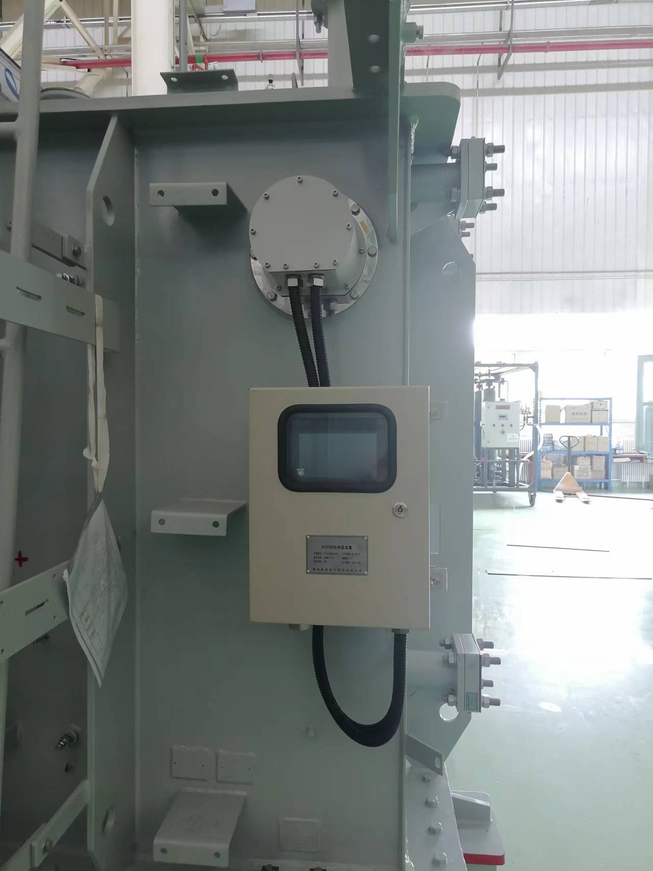
Вимірювання температури волоконно-оптичним трансформатором
Oil-immersed transformers require monitoring both winding hotspots and oil temperatures for complete thermal management.
8.1 What Temperatures Need Monitoring in Oil Transformers?
Winding hotspot temperature represents the highest temperature in copper conductors, typically 10-15°C above top oil temperature under rated load. This is the critical parameter for insulation life.
Top oil temperature indicates overall transformer loading and cooling system effectiveness. Bottom oil temperature helps assess oil circulation and identifies stratification problems.
Monitoring all three temperatures simultaneously with флуоресцентний оптоволоконний моніторинг provides complete thermal characterization and early fault detection.
8.2 How Many Measurement Points are Needed?
Each phase winding should have dedicated hotspot sensors. Large three-phase transformers typically use 9-12 winding sensors plus 2-3 oil temperature points.
Перемикачі під навантаженням (РПН) benefit from additional monitoring due to contact resistance heating. Bushing terminals on extra-high voltage transformers also warrant temperature monitoring.
Розподіл трансформаторів (10-35Клас КВ) generally use 3-6 всього каналів, while large power transformers (110кВ і вище) may employ 12-24 канали для повного охоплення.
8.3 How to Install Fiber Sensors in Oil Tanks?
Люмінесцентні датчики температури for oil tanks use probes encased in stainless steel sheaths compatible with transformer oil. Fibers penetrate tank walls through special sealed fittings that maintain oil containment.
Sensors remain stable during years of oil immersion—installations in Middle East power stations since 2011 show no degradation. Proper sealing prevents moisture ingress while allowing thermal equilibrium.
Installation requires complete oil drainage for winding-mounted sensors, while top/bottom oil sensors can sometimes be installed through existing gauge ports. All installations must occur during scheduled outages.
9. Which Power Transformers Need Temperature Monitoring?
Not all transformers justify the investment in моніторинг волоконно-оптичних трансформаторів, but certain categories show clear benefits.
9.1 What Capacity Transformers Require Monitoring?
Large power transformers above 10MVA represent significant capital investments where monitoring costs become negligible compared to replacement expenses. These units almost always benefit from comprehensive temperature monitoring.
Розподіл трансформаторів (100-2000kva) may warrant monitoring in critical applications or when operating near limits, but standard units in redundant networks often rely on simpler protection.
The decision depends on consequence of failure: a hospital or data center backup transformer justifies monitoring regardless of size, while one of many parallel units in a grid may not.
9.2 Which Voltage Levels Benefit Most?
Трансформатори високої напруги (110кВ і вище) experience the strongest electrical interference, виготовлення Флуоресцентні волоконно -оптичні датчики’ EMI immunity especially valuable. These units also have highest replacement costs, justifying monitoring investment.
Medium-voltage transformers (10-35кВ) in industrial plants, господарські будівлі, and substations increasingly use temperature monitoring as equipment costs have decreased and reliability expectations have increased.
Low-voltage transformers rarely need sophisticated monitoring unless they serve critical loads or operate in harsh environments.
9.3 What Special Transformers Need Thermal Monitoring?
Rectifier transformers supplying DC loads experience harmonic heating that makes тепловий моніторинг трансформатора essential for preventing hotspot failures.
Traction transformers in railways operate under highly variable loads with frequent overloads, requiring continuous temperature tracking for safe operation.
Furnace transformers supplying arc furnaces and induction heaters face extreme duty cycles and benefit significantly from real-time hotspot monitoring.
Wind farm transformers in remote offshore or mountain locations justify monitoring to minimize maintenance visits and prevent failures in harsh environments.
10. How to Prevent Transformer Faults Through Hotspot Monitoring?
Effective use of Вимірювання температури волоконно-оптичного волокна data prevents most thermal-related failures.
10.1 What Temperature Thresholds Trigger Alarms?
Multi-level alarm schemes provide graduated warnings. First-level alarms at 10-15°C below maximum rated temperature alert operators to elevated conditions requiring attention.
Second-level alarms at maximum rated hotspot temperature (typically 110-140°C depending on insulation) indicate need for load reduction or investigation.
Emergency trip settings 10-20°C above rated temperature provide last-line protection against insulation damage, automatically removing the transformer from service.
Rate-of-rise alarms complement absolute temperature limits—rapid changes often indicate faults even if absolute temperature remains within limits.
10.2 What Faults Can Be Detected by Temperature?
Winding short circuits create localized heating visible as sudden temperature spikes in specific sensors while others remain normal. This signature distinguishes internal faults from external conditions.
Core overheating from multipoint grounding appears as gradually increasing temperatures in core-adjacent sensors even under constant load.
Poor contact resistance at terminals or tap changers shows as abnormal temperature at specific measurement points, often accompanied by load-dependent variation.
Cooling system failures produce characteristic patterns: blocked radiators cause overall rise while pump failures show reduced temperature difference between top and bottom oil.
10.3 How Does Temperature Data Support Maintenance?
Trending analysis reveals gradual degradation before failures occur. Slowly increasing baseline temperatures under identical loads indicate developing problems like cooling blockages or increased losses.
Thermal life assessment uses cumulative temperature exposure to estimate remaining insulation life, optimizing replacement timing rather than relying solely on age.
Maintenance scheduling becomes condition-based: rather than time-based oil sampling or inspections, interventions occur when temperature trends indicate actual need.
Early-warning patterns allow planned outages for repairs rather than reactive emergency responses to failures, зниження витрат і підвищення надійності.
11. How to Integrate Temperature Monitoring System?
Сучасний флуоресцентний оптоволоконний моніторинг systems integrate seamlessly with existing infrastructure.
11.1 Can It Connect to Existing SCADA Systems?
Standard industrial protocols including Modbus RTU/TCP, DNP3, і IEC 61850 enable direct connection to substation SCADA and energy management systems.
Аналогові виходи (4-20Ма) and digital relay contacts provide simple integration with traditional transformer protection and control schemes.
Ethernet connectivity supports remote monitoring through secure VPN connections, allowing expert analysis from central engineering offices.
Onboard data logging stores months of temperature history at 1-second resolution, enabling post-event analysis and trending without continuous SCADA polling.
11.2 How Does It Work with Protection Systems?
Temperature monitoring integrates into transformer protection logic alongside electrical relays. Multi-stage alarm outputs can initiate cooling fan startup, скидання навантаження, or emergency trip.
Cooling system interlocks use temperature feedback to automatically control fans and pumps, maintaining optimal thermal conditions while minimizing auxiliary power consumption.
Load management systems can reduce transformer loading automatically when temperatures approach limits, preventing damage during peak demand periods.
Emergency trip contacts provide hardware-based protection independent of communication systems—if hotspot temperature exceeds critical limits, the transformer trips immediately regardless of SCADA status.
12. How to Install Fluorescent Temperature Sensors?
Proper installation ensures accurate Вимірювання температури волоконно-оптичного волокна і довгострокову надійність.
Розміщення датчика
Sensors must locate within millimeters of actual hotspots for accurate readings. У сухих трансформаторах, this means embedding between winding layers. In oil-immersed units, sensors position adjacent to high-current conductors.
Fiber Optic Routing
Optical fibers require minimum bend radius (typically 25-50mm) to prevent signal loss. Routes through transformer structures avoid sharp edges and provide strain relief at exit points.
Installation Safety Requirements
All sensor installation work requires complete transformer de-energization and isolation. Lockout/tagout procedures must be followed strictly. Oil-filled transformers need draining before accessing internal winding sensors.
Installation during initial manufacturing is ideal, allowing optimal sensor placement. Retrofit installations work best during planned major maintenance outages when transformers are already offline.
Cannot Install While Energized
Unlike some monitoring equipment that can be added under load, флуоресцентні датчики температури require direct physical access to windings and other internal components. This necessitates scheduled outages—transformers must be completely shut down during installation.
13. Практичні приклади з реального світу
Global installations demonstrate флуоресцентний оптоволоконний моніторинг effectiveness across diverse applications and environments.
13.1 Близький Схід: 132kV Oil-Immersed Transformer in Desert Power Station
A 50MVA 132/33kV power transformer in a Saudi Arabian desert substation experienced frequent overheating alarms from conventional winding temperature indicators during summer peaks when ambient temperatures exceeded 50°C.
12-канальний Моніторинг флуоресцентного волоконно -оптичного температури system installed during 2019 maintenance provided accurate hotspot data, revealing that actual winding temperatures remained within safe limits despite high oil temperatures. The utility safely increased loading by 15% during peak demand based on real hotspot measurements.
The system detected a developing cooling pump issue in summer 2023 through gradually increasing temperature differentials, enabling repair during a scheduled outage rather than emergency failure during peak load season.
13.2 Південно-Східна Азія: Dry-Type Transformer Monitoring in Tropical Climate
A 2000kVA dry-type transformer serving a Singapore data center required continuous operation in high humidity and 35°C ambient conditions. Traditional thermal protection provided inadequate hotspot monitoring for the critical load.
A 6-channel флуоресцентний датчик температури система встановлена в 2020 monitors each phase winding plus core temperatures. The system safely allows 120% rated load during peak computing demand while maintaining thermal limits.
Continuous temperature data confirmed that high humidity did not affect thermal performance, enabling the facility to defer expensive transformer replacement and achieve 99.99% uptime over four years of operation.
13.3 Африка: Mining Operation Rectifier Transformer Protection
A 25MVA rectifier transformer supplying copper electrowinning operations in Zambia experienced premature failures due to harmonic heating. The remote location made failures extremely costly due to production losses and long repair times.
An 8-channel моніторинг волоконно-оптичних трансформаторів система встановлена в 2018 tracks winding hotspots and rectifier connection temperatures. The system revealed harmonic-induced hotspots 40°C above expected temperatures, prompting installation of harmonic filters.
Predictive maintenance based on temperature trends has prevented two projected failures since 2018, уникнення оцін $2.3 million in lost production and emergency repairs. The transformer now operates reliably supporting continuous mining operations.
13.4 Global Wind Farm: Box Transformer Temperature Control
Wind farm transformers across offshore installations in Europe and mountain sites in South America face extreme temperature variations and limited maintenance access. Conventional monitoring proved unreliable in these environments.
Флуоресцентні волоконно -оптичні датчики deployed across 150+ wind turbine transformers since 2015 have demonstrated superior reliability in salt spray, icing conditions, and temperature swings from -40°C to +60°C ambient.
Remote monitoring enables condition-based maintenance visits rather than time-based schedules, зниження витрат на технічне обслуговування 35% while improving reliability. Failure rates decreased 60% compared to unmonitored sister sites, with early detection preventing multiple catastrophic failures.
14. What are the Key Performance Specifications?
Флуоресцентні волоконно-оптичні системи вимірювання температури deliver performance specifications optimized for transformer applications:
- Точність вимірювання: ±1°C across operating range
- Діапазон температури: -40°C до +260 °C (covers all transformer applications)
- Час відповіді: Під 5 секунд для швидкого виявлення несправності
- Ємність каналу: 1 до 64 незалежні температурні точки
- Термін служби датчика: Над 20 years with no performance degradation
- Калібрування: Заводське калібрування, повторне калібрування на місці не потрібно
- Імунітет EMI: Complete immunity to all electrical interference
15. Часті запитання
How long do fluorescent fiber optic sensors last?
Люмінесцентні датчики температури maintain accuracy for over 20 років без деградації. Інсталяції від 2011 continue operating with original calibration accuracy, demonstrating exceptional long-term stability.
Why don’t fluorescent sensors need periodic calibration?
Unlike electrical sensors that experience component aging and drift, fluorescence decay time depends on fundamental physical properties of rare-earth materials that remain absolutely constant over time. This eliminates calibration requirements entirely.
Must transformers be de-energized for sensor installation?
Так, safe installation of моніторинг волоконно-оптичних трансформаторів sensors requires complete de-energization. Sensors embed in or adjacent to windings, necessitating transformer shutdown. Installation typically occurs during planned maintenance outages.
How should alarm temperature thresholds be set?
Alarm levels depend on insulation class and transformer design. Typical settings include warning alarms 10-15°C below maximum rated hotspot, high temperature alarms at rated maximum, and emergency trip 10-20°C above rated. Consult manufacturer specifications for specific transformers.
Should I choose single-channel or multi-channel systems?
Distribution transformers under 2MVA often use 1-3 Канали. Середні трансформатори (2-10MVA) typically need 3-6 Канали. Large power transformers above 10MVA benefit from 9-24 channels providing comprehensive coverage. Critical transformers warrant more channels regardless of size.
What happens if a fiber optic cable breaks?
З fluorescent fiber optic measurement system detects fiber breaks immediately and generates fault alarms. The specific broken channel shows error status while other channels continue normal operation. Repair involves replacing the damaged fiber section during the next scheduled outage.
How does accuracy compare to PT100 RTDs?
Fluorescent sensors provide ±1°C accuracy matching or exceeding Class A PT100 performance. На відміну від RTD, fluorescent sensors maintain this accuracy indefinitely without drift and experience no interference from electromagnetic fields present in transformer environments.
Are fluorescent sensors suitable for all transformer types?
Так, флуоресцентні датчики температури work in dry-type, масляний, лита смола, and all other transformer configurations. The wide temperature range (-40°C до +260 °C) covers all applications from distribution to large power transformers.
How do fluorescent sensors perform in extreme climates?
Installations in Middle East deserts (+50°C навколишнього середовища), Арктичні регіони (-40°C), тропічна вологість, and offshore salt spray demonstrate excellent reliability. Датчики’ all-optical design eliminates environmental sensitivity issues affecting electrical sensors.
16. Звертайтеся за консультацією спеціаліста
Для отримання додаткової інформації про fluorescent fiber optic transformer monitoring systems, our technical experts provide comprehensive support:
- Free technical consultation and customized monitoring system design
- Технічні характеристики продукції, технічну документацію, та проектні пропозиції
- Application engineering support for new and retrofit installations
- On-site demonstrations and training programs
Виробник: Fuzhou Innovation Electronic Scie&Тех Ко., Тов.
Встановлено: 2011
Електронна пошта: web@fjinno.net
WhatsApp/WeChat/телефон: +86-13599070393
QQ: 3408968340
Адреса: Промисловий парк Liandong U Grain Networking, №12 Xingye West Road, Фучжоу, Фуцзянь, Китай
Веб-сайт: www.fjinno.net
17. Відмова від відповідальності
The technical information and data provided in this article are for reference purposes only. Specific monitoring solutions must be designed based on actual transformer operating conditions, Фактори навколишнього середовища, і вимоги до програми.
Sensor installation and system integration must follow manufacturer technical specifications and industry safety standards. All installation work must be performed during scheduled outages by qualified technical personnel with proper training and certification.
Performance specifications represent typical values. Фактична продуктивність повинна бути перевірена шляхом заводських приймальних випробувань і введення в експлуатацію. Applications in extreme environments or specialized transformers may require customized solutions.
This guide does not constitute engineering specifications for procurement or installation. Consult with qualified transformer monitoring specialists and follow all applicable electrical safety codes and standards in your jurisdiction.

Волоконно-оптичний датчик температури, Інтелектуальна система моніторингу, Виробник розподіленого волоконно-оптичного волокна в Китаї
 |
 |
 |