 INNO fiber optik sıcaklık sensörleri ,sıcaklık izleme sistemleri.
- Fiber optic temperature monitoring systems provide ±1°C accuracy with direct contact measurement, eliminating emissivity errors that plague infrared detection methods
- Fluorescence-based fiber sensors offer complete electromagnetic immunity, making them ideal for high-voltage transformer environments where infrared devices suffer interference
- Sürekli 24/7 online monitoring through fiber optic systems detects developing thermal faults weeks before periodic infrared inspections could identify them
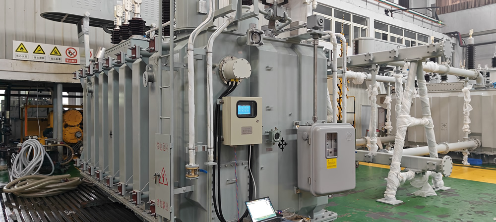
- Fiber optic sensors access internal transformer components including winding hot spots and oil temperatures that remain invisible to external infrared cameras
- Multi-point fiber optic configurations support 1-64 simultaneous measurement channels, enabling comprehensive thermal mapping across transformer windings and oil circuits
- Fiber optic technology delivers 25+ year service life without calibration requirements, while infrared equipment needs annual recalibration and maintenance
- All-dielectric fiber construction withstands voltage exposures exceeding 100kV, ensuring safe operation in proximity to energized transformer components
- Real-time fiber optic monitoring systems integrate seamlessly with SCADA networks through RS485 interfaces for centralized fault detection and predictive maintenance
- Infrared thermography serves as a valuable complementary technology for external surface surveys but cannot replace embedded fiber optic sensing for critical measurements
- Professional manufacturers like FJINNO deliver complete fluorescence fiber monitoring solutions with proven reliability in demanding power system applications since 2011
1. Why Does Accurate Temperature Monitoring Matter for Transformer Reliability?

Thermal Stress as Primary Cause of Transformer Failures
Temperature elevation represents the most critical factor affecting transformer winding insulation degradation and operational lifespan. Research demonstrates that every 8-10°C increase in operating temperature halves the expected service life of cellulose insulation materials. Winding temperature monitoring systems provide essential data for preventing thermal runaway conditions that lead to catastrophic failures.
Excessive heat generation in trafo sargıları stems from multiple sources including resistive losses in conductors, eddy current heating, and localized hot spots caused by circulating currents or poor cooling circulation. Without accurate temperature measurement systems, these thermal anomalies progress undetected until insulation breakdown occurs. Profesyonel fiber optic monitoring solutions from manufacturers like FJİNNO enable early detection of developing thermal problems.
Oil Temperature Management and Insulation Protection
Trafo yağı sıcaklığı serves dual functions as both cooling medium and electrical insulation. Elevated oil temperatures accelerate oxidation processes, producing acidic compounds that attack cellulose insulation and metallic components. Oil temperature monitoring provides critical data for assessing cooling system performance and identifying circulation problems.
Hot Spot Temperature and Insulation Aging
The hottest point within trafo sargıları, typically located in upper disk sections where cooling is least effective, determines insulation aging rate. International standards including IEEE C57.91 and IEC 60076-7 recognize hot spot temperature as the fundamental parameter for transformer loading calculations and life expectancy assessments. Kesin sıcak nokta izleme requires direct measurement through embedded sensors rather than indirect calculation methods.
Regulatory Standards and Grid Reliability Requirements
Modern power system operators demand comprehensive trafo izleme to ensure grid stability and minimize unplanned outages. Regulatory frameworks increasingly mandate online temperature monitoring systems for critical transmission transformers. Arasındaki seçim fiber optik Ve infrared monitoring technologies significantly impacts compliance capability and operational reliability.
2. What Are the Fundamental Principles Behind Fiber Optic Temperature Sensing Technology?

Fluorescence-Based Temperature Measurement Physics
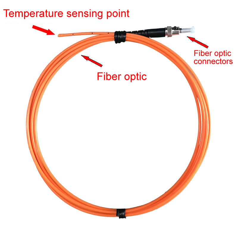
Floresan fiber optik sıcaklık sensörleri utilize rare-earth phosphor materials exhibiting temperature-dependent luminescence decay characteristics. When excited by a brief optical pulse, these phosphor compounds emit fluorescence that decays exponentially with a time constant directly related to absolute temperature. This measurement principle operates independently of light intensity, lif kayıpları, or connector variations.
The fiber optik demodülatör transmits excitation light pulses through the fluorescence fiber cable to the sensor probe, captures returning fluorescence emissions, and precisely measures decay time using high-speed photodetectors and digital signal processing. Advanced algorithms extract accurate temperature values across the full -40°C to 260°C operating range with ±1°C precision.
Point-Type Sensor Configuration and Specifications
Floresan fiber sensörler employ point-type configurations enabling precise localized temperature measurement at specific critical locations within trafo sargıları and oil circuits. Key technical specifications include:
| Parametre | Şartname | Avantaj |
|---|---|---|
| Ölçüm Doğruluğu | ±1°C | Eliminates emissivity uncertainty |
| Sıcaklık Aralığı | -40°C ila 260°C | Covers all transformer operating conditions |
| Tepki Süresi | <1 ikinci | Captures transient thermal events |
| Prob Çapı | 2-3mm | Minimally invasive installation |
| Elyaf Uzunluğu | 0-80 metre | Flexible installation routing |
| Dielektrik Dayanımı | >100kV | Safe operation in HV environments |
| Servis Ömrü | >25 yıllar | Matches transformer operational lifetime |
Multi-Channel Monitoring System Architecture
Fiber optik sıcaklık izleme sistemleri support scalable multi-channel configurations accommodating 1 ile 64 individual sensör kanalları from a single demodulator unit. Time-division multiplexing or wavelength-division multiplexing techniques enable sequential interrogation of multiple sensors, providing comprehensive thermal mapping karşısında trafo sargıları, oil circuits, and cooling systems.
Communication and Integration Capabilities
Modern fiber optic monitoring equipment incorporates RS485 communication interfaces supporting Modbus protocol for integration with SCADA systems and substation automation networks. Monitoring software platforms provide real-time data visualization, tarihsel trend, automated alarming, and remote access capabilities. Professional systems from FJİNNO include comprehensive software packages supporting multi-site management and predictive analytics.
3. How Does Infrared Temperature Measurement Technology Work in Transformer Applications?
Thermal Radiation Detection Principles
Kızılötesi sıcaklık ölçümü operates on the principle that all objects emit electromagnetic radiation proportional to their absolute temperature according to the Stefan-Boltzmann law. Infrared thermography devices detect this thermal radiation using semiconductor sensors sensitive to wavelengths in the 8-14 micrometer range, converting radiant energy into temperature readings.
The fundamental challenge with kızılötesi ölçüm lies in the emissivity factor—the ratio of radiation emitted by a real surface compared to an ideal blackbody at the same temperature. Different materials exhibit varying emissivity values, and incorrect emissivity settings introduce significant measurement errors. Transformer surfaces present particular challenges due to diverse materials including painted metal tanks, porcelain insulators, and oil-wetted surfaces.
Infrared Equipment Types for Transformer Monitoring
Three categories of infrared devices find application in transformer temperature assessment:
| Device Type | Başvuru | Sınırlamalar |
|---|---|---|
| Handheld IR Thermometers | Periodic spot measurements | Single-point readings, manual operation |
| Termal Görüntüleme Kameraları | Comprehensive surface surveys | Yalnızca periyodik muayene, weather-dependent |
| Fixed IR Monitoring Systems | Continuous external monitoring | Surface temperatures only, high cost |
Technical Parameters and Performance Characteristics
Tipik infrared thermography systems için transformer applications feature temperature ranges from -40°C to 500°C, thermal sensitivity of 0.05°C, and spatial resolution determined by detector array size and optics. Fakat, achievable accuracy ranges from ±2°C to ±5°C depending on emissivity uncertainty, atmospheric absorption, and measurement distance.
Environmental Factors Affecting Infrared Measurements
Infrared temperature detection suffers from multiple environmental interference sources including solar radiation reflection, atmospheric water vapor absorption, rain and fog attenuation, and ambient temperature effects on detector performance. These factors necessitate careful measurement timing and conditions, limiting practical applicability for continuous trafo izleme.
4. Measurement Accuracy and Precision: Technical Performance Comparison Tables
Fundamental Accuracy Comparison
| Performans Parametresi | Fiber Optik İzleme | Infrared Measurement |
|---|---|---|
| Ölçüm Prensibi | Doğrudan iletişim, floresans bozulması | Temassız, thermal radiation detection |
| Tipik Doğruluk | ±1°C | ±2°C to ±5°C |
| Emissivity Dependency | Hiçbiri (contact measurement) | Yüksek (5-10% error from emissivity) |
| Repeatability | ±0,5°C | ±1°C to ±3°C |
| Uzun Vadeli Kararlılık | No drift over 25+ yıllar | Requires annual recalibration |
| Tepki Süresi | <1 ikinci | 0.1 ile 1 ikinci (camera dependent) |
Measurement Error Sources Analysis
Fiber optik sıcaklık sensörleri eliminate the primary error sources affecting infrared measurements. The contact-based measurement principle of floresans sensörleri ensures thermal equilibrium between the sensor probe and measured component, providing true temperature readings independent of surface properties.
| Error Source | Impact on Fiber Optic | Impact on Infrared |
|---|---|---|
| Surface Emissivity Variation | No effect | ±5-10% error |
| Reflected Radiation | No effect | ±3-8% error |
| Atmospheric Absorption | No effect | ±2-5% error (distance dependent) |
| Ambient Temperature Changes | Asgari (<0.2°C) | ±1-3°C (detector compensation required) |
| Measurement Angle | No effect | Significant (emissivity changes with angle) |
Winding Hot Spot Detection Accuracy
Kritik için transformer winding monitoring uygulamalar, measurement accuracy directly impacts loading decisions and life expectancy calculations. Fiber optik sensörler embedded within winding structures provide direct hot spot temperature readings with ±1°C accuracy, sırasında infrared measurements can only estimate internal temperatures based on external surface readings and thermal modeling.
Oil Temperature Measurement Precision
Trafo yağı sıcaklığı izleme requires accuracy sufficient to detect gradual temperature increases indicating cooling system degradation or loading changes. Fiber optik sensörler immersed directly in oil circuits measure precise temperatures at multiple elevations, enabling detection of stratification and circulation problems. Kızılötesi termografi can only assess tank surface temperatures, which may differ significantly from internal oil temperatures depending on ambient conditions and tank insulation.
5. Electromagnetic Interference Immunity: Why Fiber Optics Excel in High-Voltage Environments
All-Dielectric Construction Advantages
The complete absence of metallic components in floresan fiber optik sensör assemblies provides inherent immunity to electromagnetic interference. Fiber optik kablolar transmit optical signals through glass or plastic waveguides, remaining unaffected by intense electric and magnetic fields surrounding güç trafosu teçhizat.
| Interference Source | Fiber Optic Response | Infrared Device Response |
|---|---|---|
| Strong Electric Fields | No effect | Potential electronic interference |
| Magnetic Fields | No effect | Minimal effect on modern equipment |
| Switching Transients | No effect | May cause temporary disruption |
| Lightning Strikes | No effect | Risk of equipment damage |
| Ground Potential Rise | No effect (galvanic isolation) | Potential damage if grounded improperly |
High-Voltage Insulation Performance
Fiber optik sıcaklık sensörleri withstand voltage exposures exceeding 100kV without breakdown, enabling direct mounting on energized transformer components. This high dielectric strength permits sensor placement at optimal measurement locations within winding structures and oil circuits without creating additional flashover risk or partial discharge sources.
Grounding and Safety Considerations
The galvanic isolation provided by fiber optic systems eliminates ground loops and common-mode voltage issues that complicate electrical sensor installations. Infrared monitoring equipment requires careful grounding and surge protection, particularly for fixed installations near high-voltage equipment. Personnel safety during infrared inspections necessitates maintaining proper clearance distances and following live-line work procedures.
Substation Environment Reliability
Fiber optik izleme sistemleri demonstrate superior reliability in demanding substation environments characterized by electrical noise, weather extremes, and contamination. The optical measurement principle remains immune to electromagnetic coupling, capacitive coupling, and conductive interference paths affecting electronic equipment. FJINNO fiber optic monitoring solutions provide consistent performance across 110kV to 750kV voltage classes without special shielding or filtering requirements.
6. Monitoring Coverage and Accessibility: Internal vs External Temperature Detection
Internal Temperature Measurement Capabilities
Fiber optik sensörler access measurement locations impossible to reach with infrared technology. Gömülü sarma sıcaklık sensörleri positioned during transformer manufacturing or installed through access ports during retrofits provide direct readings from hot spot locations deep within winding structures. This internal access represents a fundamental advantage for accurate termal izleme.
| Ölçüm Yeri | Fiber Optic Access | Infrared Access |
|---|---|---|
| Dolambaçlı Sıcak Noktalar | Direct embedded measurement | Cannot detect (internal location) |
| Oil Temperature (Tepe) | Immersed sensor, precise reading | Tank surface estimation only |
| Oil Temperature (Bottom) | Direct measurement at any depth | Not accessible |
| Between Winding Disks | Multiple sensors at various elevations | Cannot detect (internal location) |
| Core Hot Spots | Sensor placement at critical points | Cannot detect (shielded by tank) |
| Tank Surface | External sensors if needed | Primary measurement capability |
Multi-Point Temperature Distribution Mapping
Kapsayıcı transformer thermal monitoring requires simultaneous measurement at multiple locations to identify temperature gradients and circulation patterns. Fiber optik izleme sistemleri supporting up to 64 channels enable extensive sensor arrays throughout winding structures and oil circuits. This multi-point capability reveals developing problems through pattern analysis rather than relying on single-point measurements.
Blind Spots and Coverage Limitations
Kızılötesi termografi can only assess surfaces visible to the camera, creating significant blind spots for trafo izleme. Internal components, oil temperatures beneath tank surfaces, and areas obscured by radiators, piping, or structural elements remain inaccessible. Fiber optik sensörler eliminate these blind spots through strategic placement at critical measurement points regardless of visibility.
Cooling System Performance Assessment
Etkili transformer cooling system monitoring requires temperature measurement at oil inlet and outlet points, across radiator banks, and at various tank elevations. Fiber optic sensor arrays map oil circulation patterns, detect blocked cooling passages, and identify failing pumps or fans through temperature distribution analysis. Infrared surveys provide limited cooling system assessment through external radiator temperature patterns but cannot access internal oil circuit temperatures.
7. Real-Time Continuous Monitoring vs Periodic Inspection: Operational Reliability Comparison
Continuous Data Acquisition Advantages
Fiber optik sıcaklık izleme sistemleri sağlamak 24/7 continuous data streams enabling real-time thermal surveillance. The monitoring host interrogates all connected sensör kanalları at intervals under one second, building comprehensive time-series databases for trend analysis. This continuous approach detects gradual temperature increases or sudden thermal transients immediately upon occurrence.
| Monitoring Aspect | Fiber Optic Online System | Infrared Periodic Inspection |
|---|---|---|
| Data Collection Frequency | Sürekli (<1 second updates) | Üç ayda bir, monthly, or annual |
| Fault Detection Window | Immediate detection | Weeks to months delay |
| Trend Analizi | Complete historical records | Limited snapshot comparisons |
| Transient Event Capture | All events recorded | Likely missed between inspections |
| Weather Dependency | Hiçbiri | Clear conditions required |
| Night Operation | Full capability | Possible but less effective |
| Automated Alarming | Multi-level thresholds, automatic | Manual interpretation required |
Early Warning and Predictive Maintenance
The continuous nature of fiber optik izleme enables early detection of developing thermal problems weeks or months before catastrophic failure. Gradual temperature increases indicating insulation deterioration, cooling system degradation, or increasing load losses become apparent through trend analysis. Infrared inspections conducted quarterly or annually may miss critical periods of temperature elevation occurring between scheduled surveys.
Load-Correlated Temperature Analysis
Profesyonel izleme platformları correlate sıcaklık verileri with load current profiles, ortam koşulları, and operational history to distinguish normal load-related heating from abnormal thermal behavior. This contextual analysis requires continuous data streams unavailable from periodic infrared inspections. Automated diagnostic algorithms identify deviations from expected thermal performance, triggering alarms for investigation.
SCADA Integration and Remote Access
Fiber optik sıcaklık izleme sistemleri integrate seamlessly with substation automation infrastructure through RS485 Modbus interfaces or Ethernet connectivity. Transformer temperature data flows to central control rooms, enabling remote monitoring of distributed assets without site visits. Infrared inspection data requires manual collection, tercüme, and entry into asset management systems, introducing delays and potential errors.
8. Installation Requirements and System Integration: Technical Implementation Analysis
Fiber Optic Sensor Installation Methods
Uygulanması fiber optik sıcaklık izleme varies depending on whether installation occurs during transformer manufacturing or as a retrofit to operating equipment. New transformers accommodate sensör yerleşimi içinde winding structures during assembly, positioning probes at calculated hot spot locations. Retrofit installations utilize access ports or oil sampling valves for sensor insertion into oil circuits.
| Installation Aspect | Fiber Optic System | Infrared Equipment |
|---|---|---|
| Transformer Outage Required | Evet (for internal sensors) | HAYIR (external mounting) |
| Sensor Placement Precision | Exact location targeting | Limited by line-of-sight |
| Invasiveness | Asgari (2-3mm probes) | Temassız |
| Cable Routing | Fiber cables to demodulator | Power and data cables |
| Environmental Protection | Sealed sensor probes | Weather-rated enclosures |
| Commissioning Time | 4-8 saat | 2-4 saat |
Sistem Mimarisi ve Bileşenleri
Tam bir fiber optic monitoring system comprises multiple integrated components. Floresan fiber sensörler connect via optical cables to the demodulator unit, which processes fluorescence signals and generates temperature data. The monitoring host provides local display, veri kaydı, ve iletişim arayüzleri. Monitoring software runs on dedicated computers or integrates with existing SCADA workstations.
Communication Infrastructure Requirements
Fiber optic temperature monitoring equipment requires communication links for data transmission and remote access. Standard RS485 serial connections support distances up to 1200 meters using twisted-pair cabling. Ethernet connectivity enables longer distances and higher bandwidth but requires network infrastructure. Infrared monitoring systems have similar communication requirements for fixed installations, while portable devices store data locally for manual download.
Integration with Transformer Protection Systems
Gelişmiş monitoring implementations integrate temperature data with transformer protection and control systems. Fiber optic monitoring outputs can trigger alarms, initiate load reduction, or activate emergency cooling through programmable logic. This integration enables automated protective responses to thermal overloads. Infrared inspection results require manual interpretation and decision-making without automated protection capability.
FJİNNO provides comprehensive monitoring system packages including optical demodulators, sensor probes, ekran modülleri, fluorescence fiber cables, monitoring software platforms, ve teknik destek. All systems meet CE, EMC, and ISO certification standards ensuring reliable operation in demanding power system environments.
9. Long-Term Reliability and Maintenance: Service Life Comparison
Fiber Optic Sensor Longevity and Stability
Floresan fiber optik sensörler demonstrate exceptional operational lifetimes exceeding 25 years without performance degradation. The all-dielectric construction eliminates corrosion, electrical stress, and mechanical wear affecting conventional sensing technologies. Sealed probe designs prevent moisture ingress, kirlenme, and oil degradation from impacting sensor operation.
| Reliability Factor | Fiber Optik Sensörler | Infrared Equipment |
|---|---|---|
| Typical Service Life | >25 yıllar | 10-15 yıllar (detector replacement) |
| Calibration Drift | Hiçbiri (physical principle stable) | Annual verification recommended |
| Environmental Degradation | Asgari (sealed construction) | Lens contamination, detector aging |
| Bakım Gereksinimleri | Hiçbiri (bakım gerektirmez) | Temizlik, kalibrasyon, component replacement |
| MTBF (Mean Time Between Failures) | >200,000 saat | 50,000-100,000 saat |
Maintenance-Free Operation Benefits
The fundamental measurement principle of fluorescence fiber sensors provides inherent stability without calibration drift. Unlike thermocouple or RTD sensors requiring periodic verification, fluorescence decay time measurement remains constant over decades. Initial factory calibration suffices for the sensor’s entire operational life, eliminating scheduled maintenance and recalibration costs.
System Availability and Uptime
Fiber optik izleme sistemleri achieve availability exceeding 99.9% through redundant design options and robust component construction. The absence of moving parts, kimyasal reaksiyonlar, or electrical contacts contributing to degradation ensures continuous operation. Infrared equipment requires periodic lens cleaning, detector recalibration, and eventual component replacement affecting system availability.
Data Quality and Historical Trending
Long-term measurement stability enables meaningful historical trend analysis using fiber optic monitoring data. Temperature patterns spanning years reveal gradual changes in transformer thermal performance indicating insulation aging, cooling system deterioration, or loading changes. This longitudinal analysis capability depends on consistent sensor accuracy without calibration shifts.
Infrared inspection records suffer from variability between operators, teçhizat, and environmental conditions during measurements. Comparing infrared surveys conducted years apart introduces uncertainty from these uncontrolled variables, limiting trend reliability.
10. Which Monitoring Technology Should You Choose for Your Transformer Application?
Critical Transformer Applications: Fiber Optic Monitoring Recommendation
For mission-critical güç transformatörleri where reliability is paramount and unplanned outages create significant consequences, fiber optik sıcaklık izleme sistemleri represent the optimal technology choice. The combination of superior accuracy, continuous operation, internal access, elektromanyetik bağışıklık, and maintenance-free longevity justifies implementation despite higher initial installation requirements.
Recommended Fiber Optic Configurations by Application
| Trafo Tipi | Önerilen Sensörler | Ölçüm Noktaları |
|---|---|---|
| Dağıtım (110-220kV) | 4-8 kanallar | Winding hot spots (2-3), üst yağ (1), alt yağ (1) |
| Transmission (330-500kV) | 8-16 kanallar | Multiple winding locations (4-8), oil circuit (4-6) |
| EHV/UHV (750kV+) | 16-32 kanallar | Comprehensive winding mapping, detailed oil profiling |
Complementary Use of Infrared Thermography
Sırasında fiber optik izleme provides superior performance for continuous winding and oil temperature tracking, kızılötesi termografi serves valuable complementary roles in comprehensive transformer maintenance programs. Periyodik infrared surveys assess external components including tap changers, kablo bağlantıları, radyatörler, and auxiliary equipment where embedded sensors are impractical.
The optimal monitoring strategy combines continuous fiber optik algılama for critical internal measurements with periodic infrared inspections for external surveys. This integrated approach maximizes detection capability while optimizing resource allocation.
Selecting Professional Monitoring System Manufacturers
Successful implementation of trafo sıcaklığı izleme requires partnering with experienced manufacturers offering proven technology, comprehensive support, and application expertise. Key selection criteria include:
- Product certifications (CE, EMC, ISO) demonstrating quality management
- Technical capabilities in optical sensing, sinyal işleme, and power system applications
- Reference installations across voltage classes and operating environments
- Comprehensive support including design assistance, installation training, ve devreye alma
- Long-term parts availability and technical service
FJINNO Fiber Optic Monitoring Solutions
Fuzhou İnovasyon Elektronik Bilimi&Tech Co., Ltd.. (FJİNNO), kurulmuş 2011, uzmanlaşmış fluorescence fiber optic temperature monitoring systems for power transformers and electrical equipment. Their comprehensive product line includes:
- Optical demodulators supporting 1-64 sensör kanalları
- Fluorescence fiber temperature sensors with ±1°C accuracy, -40°C to 260°C range
- Monitoring software platforms with SCADA integration capability
- Complete system packages with CE, EMC, ve ISO sertifikaları
- Customizable configurations for specific transformer applications
- RS485 communication interfaces compatible with Modbus and other protocols
Contact FJINNO for expert consultation on fiber optic temperature monitoring solutions:
Fuzhou İnovasyon Elektronik Bilimi&Tech Co., Ltd..
E-posta: web@fjinno.net
WhatsApp/WeChat/Telefon: +86 135 9907 0393
QQ: 3408968340
Web sitesi: www.fjinno.net
Adres: Liandong U Tahıl Ağı Endüstri Parkı, No.12 Xingye Batı Yolu, Fuzhou, Fujian, Çin
Implementation Recommendations for New and Retrofit Projects
New transformer procurement provides optimal opportunity for fiber optic sensor installation, enabling precise positioning within winding structures during manufacturing. Specifications should require embedded sarma sıcaklık sensörleri at calculated hot spot locations plus yağ sıcaklık sensörleri at top, orta, and bottom elevations.
Retrofit projects on operating transformers face greater installation challenges but remain technically feasible. Access through oil sampling valves, drenaj portları, or inspection openings enables sensor insertion into oil circuits. While internal winding sensor placement may be impractical for retrofits, strategic oil temperature monitoring combined with external measurements provides significant improvement over periodic infrared surveys alone.
Sıkça Sorulan Sorular (SSS)
1. Çeyrek: What makes fluorescence fiber optic sensors more accurate than other temperature measurement technologies?
Floresan fiber optik sensörler achieve superior ±1°C accuracy through direct contact measurement based on temperature-dependent fluorescence decay physics. Farklı infrared systems that suffer from emissivity uncertainty, reflected radiation, and atmospheric absorption errors, the optical decay time measurement principle remains immune to these interference sources. The sensor probe establishes thermal equilibrium with measured components, providing true temperature readings without estimation or correction factors. This fundamental advantage makes fiber optik izleme the gold standard for critical trafo sargısı Ve oil temperature applications.
2. Çeyrek: How does electromagnetic immunity benefit fiber optic monitoring in high-voltage transformer environments?
Tamamen dielektrik yapı fluorescence fiber sensors provides complete immunity to electromagnetic interference in high-voltage substations. Strong electric fields, magnetic fields, geçici geçişler, and lightning strikes that disrupt electronic equipment have zero effect on optical temperature measurement. This immunity eliminates false alarms, measurement errors, and equipment damage risks associated with electrical sensors. Fiber optik problar withstand voltage exposures exceeding 100kV, enabling safe installation directly on energized trafo sargıları and internal components without creating flashover risk or partial discharge sources. FJINNO fiber optic systems operate reliably across 110kV to 750kV voltage classes without special shielding requirements.
3. Çeyrek: Why is continuous real-time monitoring superior to periodic infrared inspections for transformer protection?
Continuous fiber optic monitoring detects developing thermal problems immediately upon occurrence, providing weeks or months of early warning before catastrophic failures. The 24/7 data streams enable trend analysis identifying gradual temperature increases from insulation deterioration, cooling system degradation, or increasing load losses. Automated alarm systems trigger protective responses without human intervention. Tersine, periodic infrared inspections conducted quarterly or annually may miss critical thermal events occurring between surveys. Transient overloads, sudden cooling failures, or rapidly developing faults escape detection when monitoring gaps extend for months. Real-time fiber optic surveillance eliminates these blind spots, maximizing asset protection and grid reliability.
4. Çeyrek: Can fiber optic sensors measure internal transformer temperatures that infrared cameras cannot access?
Evet, this represents a fundamental advantage of fiber optik teknolojisi. Gömülü sarma sıcaklık sensörleri access hot spot locations deep within transformer structures that remain completely invisible to external infrared cameras. Oil temperature sensors measure precise temperatures at any depth within oil circuits, revealing stratification and circulation patterns. Kızılötesi termografi can only assess external tank surfaces, which may differ significantly from critical internal temperatures depending on insulation, ortam koşulları, and loading. This internal access capability makes fiber optik izleme essential for accurate thermal assessment of power transformers where the hottest points exist within winding structures and oil circuits.
S5: What service life and maintenance advantages do fiber optic sensors provide compared to conventional monitoring equipment?
Floresan fiber sensörler deliver maintenance-free operation exceeding 25 years without calibration drift or performance degradation. The sealed all-dielectric construction eliminates corrosion, electrical stress, and mechanical wear. Initial factory calibration remains accurate throughout the sensor’s entire operational lifetime because the fluorescence decay measurement principle is inherently stable. This contrasts sharply with thermocouples, RTD'ler, Ve infrared equipment requiring annual verification, periodic recalibration, and eventual component replacement. The superior reliability of fiber optic monitoring systems reduces life-cycle costs while maximizing system availability. FJINNO sensörleri achieve MTBF exceeding 200,000 saat, providing dependable protection matching transformer operational lifetimes.
S6: How many measurement channels can a single fiber optic monitoring system support for comprehensive transformer coverage?
Gelişmiş fiber optic demodulators support scalable configurations from 1 ile 64 individual sensör kanalları, enabling comprehensive thermal mapping across trafo sargıları, oil circuits, and cooling systems. Multi-channel capability allows simultaneous measurement at multiple winding locations, various oil elevations, and cooling system points. This extensive coverage reveals temperature distribution patterns and gradients that single-point measurements cannot detect. Time-division multiplexing interrogates all connected sensors in under one second, providing real-time thermal surveillance. FJINNO monitoring systems offer flexible channel configurations tailored to specific transformer types and monitoring requirements, from basic 4-channel distribution transformer applications to comprehensive 32-channel transmission transformer installations.
S7: Does fiber optic monitoring integrate with existing SCADA systems and substation automation infrastructure?
Fiber optic temperature monitoring equipment seamlessly integrates with substation automation through industry-standard RS485 Modbus communication interfaces. Temperature data flows to central control rooms, SCADA workstations, and asset management systems without proprietary protocols or custom interfaces. Ethernet connectivity options enable TCP/IP integration for modern networked environments. Monitoring software platforms OPC sunucuları sağlayın, web interfaces, and API access supporting diverse integration requirements. Automated alarm outputs trigger protective relay systems, activate emergency cooling, or initiate load reduction through programmable logic. This open architecture ensures fiber optic monitoring systems complement existing infrastructure investments rather than requiring separate isolated monitoring networks.
S8: What certifications and standards compliance should professional fiber optic monitoring equipment meet?
Profesyonel trafo sıcaklık izleme sistemleri must meet comprehensive certification requirements ensuring safety, elektromanyetik uyumluluk, and quality management. Essential certifications include CE marking for European markets, EMC compliance verifying electromagnetic immunity and emissions limits, ve ISO 9001 quality management system certification. Equipment should comply with relevant IEC and IEEE standards for trafo izleme including IEC 60076-7 for loading guides and IEEE C57.91 for loading and thermal considerations. FJINNO fiber optic monitoring products carry full CE, EMC, ve ISO sertifikaları, demonstrating compliance with international standards and manufacturing quality requirements. Third-party testing validates dielectric strength, temperature accuracy, and environmental performance specifications ensuring reliable operation in demanding power system applications.
S9: Can fiber optic monitoring systems detect different types of transformer thermal faults and provide diagnostic insights?
Evet, multi-point fiber optic monitoring enables sophisticated fault detection and diagnosis through temperature pattern analysis. Different thermal fault mechanisms produce characteristic temperature signatures. Blocked cooling passages create localized hot spots with abnormal gradients between adjacent sensors. Winding circulating currents generate elevated temperatures in specific winding sections. Oil pump failures produce reduced temperature differentials across cooling circuits. Core lamination problems create localized heating patterns. Gelişmiş izleme yazılımı employs diagnostic algorithms comparing measured temperature distributions against expected thermal models, automatically identifying anomalous patterns and classifying probable fault mechanisms. This diagnostic capability enables targeted maintenance rather than generic inspections, reducing downtime and repair costs.
S10: Why should critical power transformers implement fiber optic monitoring rather than relying on conventional temperature indicators?
Critical transmission transformers represent substantial capital investments where unplanned failures create severe grid reliability impacts and replacement costs exceeding millions of dollars. Conventional winding temperature indicators using indirect calculation methods introduce significant uncertainty, while periodic infrared inspections provide only intermittent surveillance. Fiber optik izleme sistemleri doğruluğu sağlamak, güvenilirlik, and continuous operation required to protect these critical assets. The combination of ±1°C precision, internal hot spot access, elektromanyetik bağışıklık, bakım gerektirmeyen çalışma, and real-time fault detection justifies implementation for transformers where reliability is paramount. FJİNNO has supplied fiber optic monitoring solutions protecting critical power transformers worldwide since 2011, with proven performance in demanding applications across all voltage classes.
Çözüm: Fiber Optic Monitoring Delivers Superior Transformer Protection

Comprehensive comparison of fiber optik Ve infrared temperature monitoring technologies reveals clear performance advantages for fluorescence fiber sensor systems in critical transformer winding and oil temperature applications. The combination of ±1°C accuracy, sürekli 24/7 operasyon, internal component access, complete electromagnetic immunity, and maintenance-free 25+ year service life positions fiber optik izleme as the optimal choice for reliable transformer asset protection.
Sırasında kızılötesi termografi serves valuable roles in periodic external equipment surveys, its fundamental limitations including surface-only measurement, emissivity uncertainty, environmental sensitivity, and periodic inspection gaps prevent it from matching the comprehensive protection capabilities of embedded fiber optic sensor systems.
Power system operators prioritizing transformer reliability, grid stability, and asset life optimization should implement fiber optik sıcaklık izleme as a standard protection measure. The technology has matured over decades of deployment in demanding applications worldwide, with manufacturers like FJİNNO delivering proven solutions meeting international quality and safety standards.
Transform your transformer monitoring strategy with proven fiber optic technology from FJINNO:
Fuzhou İnovasyon Elektronik Bilimi&Tech Co., Ltd..
E-posta: web@fjinno.net
WhatsApp/WeChat/Telefon: +86 135 9907 0393
QQ: 3408968340
Web sitesi: www.fjinno.net
Adres: Liandong U Tahıl Ağı Endüstri Parkı, No.12 Xingye Batı Yolu, Fuzhou, Fujian, Çin
Request complimentary technical consultation including application-specific sensor configuration recommendations, system architecture design, kurulum planlaması, and integration specifications. Benefit from FJINNO'lar extensive experience deploying fiber optic monitoring solutions across power systems worldwide since 2011.
Sorumluluk reddi beyanı
Teknik bilgiler, performance comparisons, and application recommendations presented in this article regarding fiber optic and infrared temperature monitoring technologies represent general guidance based on industry practices, published specifications, and engineering principles current as of publication date. While efforts have been made to ensure accuracy, specific applications require professional engineering evaluation accounting for unique operational requirements, transformer designs, çevresel koşullar, and regulatory standards.
Teknik özellikler, measurement capabilities, and system characteristics described herein are subject to variation among manufacturers and product models. Readers should verify current specifications with equipment suppliers before making procurement or implementation decisions. The comparative analysis reflects typical performance characteristics but may not apply universally to all products or applications.
Implementation of temperature monitoring systems should comply with applicable electrical codes, safety standards, manufacturer installation instructions, and utility operating procedures. Professional engineering judgment remains essential for sensor placement design, sistem konfigürasyonu, alarm threshold setting, and integration with protective systems. Users bear responsibility for ensuring monitoring equipment suitability for intended applications and maintaining systems according to manufacturer recommendations.
The mention of FJİNNO and other manufacturers serves informational purposes based on their market presence and does not constitute endorsement or guarantee of performance. No warranty, açık veya zımni, is provided regarding the completeness, kesinlik, or applicability of information presented. Liability for consequences arising from use of this information rests solely with the user.
Consultation with qualified professionals including transformer manufacturers, protection engineers, and monitoring system specialists is recommended for critical applications where equipment selection and implementation significantly impact operational safety, güvenilirlik, and economic performance.

Fiber optik sıcaklık sensörü, Akıllı izleme sistemi, Çin'de dağıtılmış fiber optik üreticisi
 |
 |
 |