 INNO fiber optic na mga sensor ng temperatura ,mga sistema ng pagsubaybay sa temperatura.
- Pagsubaybay sa temperatura ng transformer continuously tracks internal temperatures to prevent insulation degradation and thermal breakdown that lead to catastrophic equipment failure
- Hot spot temperatures in transformer windings typically run 10-15°C higher than top oil temperature and represent the most critical measurement point for assessing transformer health
- Mga sensor ng temperatura ng fiber optic provide superior accuracy (±1°C), kumpletong kaligtasan sa sakit sa electromagnetic interference, and high voltage isolation up to 100kV or more
- Strategic sensor placement at winding hot spots, nangungunang langis, core, and bushing locations enables comprehensive thermal profiling and early fault detection
- Abnormal temperature rise serves as the primary indicator of overload conditions, cooling system failure, or developing internal faults months before catastrophic failure occurs
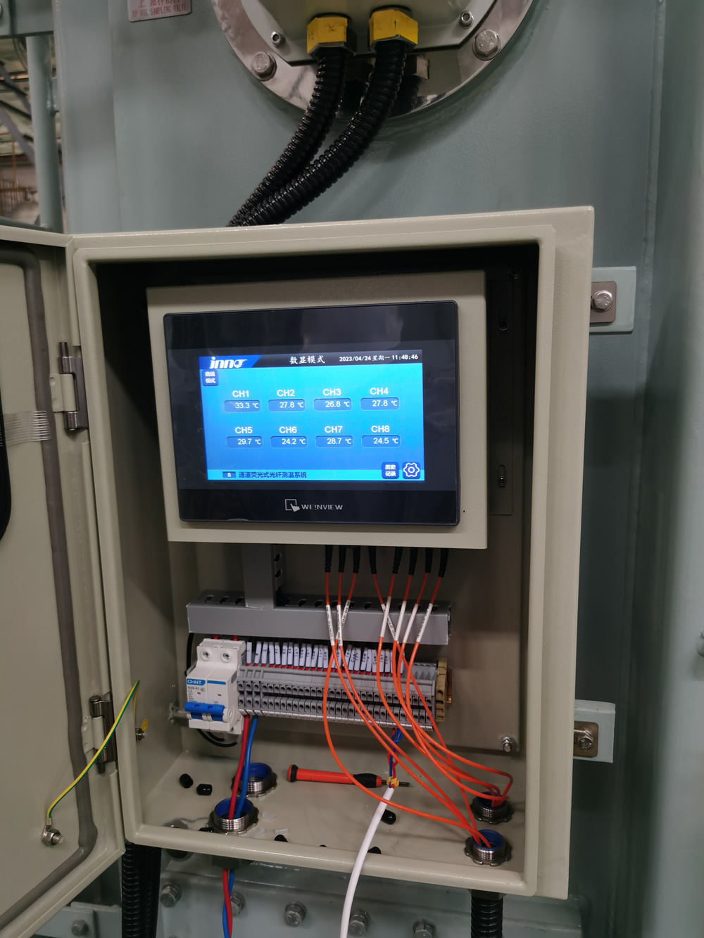
FJINNO Fluorescent Fiber Optic Temperature Monitoring System for Transformers
E-mail: web@fjinno.net
WhatsApp: +8613599070393
Ang FJINNO fluorescent fiber optic temperatura monitoring system is specifically engineered for transformer winding hot spot detection and critical thermal monitoring applications. Utilizing advanced rare-earth fluorescent crystal sensor technology, the system measures temperature by analyzing fluorescent decay time, providing immunity to electromagnetic fields, panghihimasok sa dalas ng radyo, and high voltage environments that plague conventional electronic sensors.
This system represents the most reliable solution for oil-immersed transformer temperature measurement, with sensors that can be placed directly into high-voltage winding environments without any risk of electrical interference or ground loop issues. The intrinsically safe design requires no electrical power at the sensor point, eliminating explosion risks and enabling installation in the most demanding power system applications.
Teknikal na Pagtutukoy
| Parameter | Pagtutukoy |
|---|---|
| Saklaw ng Temperatura | -40°C hanggang +260°C |
| Katumpakan ng Pagsukat | ±1°C (0 to 200°C) |
| Resolusyon | 0.1°C |
| Oras ng Pagtugon | < 2 segundo |
| Voltage Isolation | > 100kV |
| EMI Immunity | Kumpleto (fiber optic) |
| Kapasidad ng Channel | 1 sa 32 mga channel bawat yunit |
| Diameter ng Sensor | 2.5mm (standard probe) |
| IP Rating | IP65 (controller enclosure) |
| Komunikasyon | RS485, Ethernet, 4-20mA |
Pag-install at Application
Sensor Placement Guidelines:
For oil-immersed power transformers, fluorescent fiber optic probes should be installed at the following critical locations:
- Directly embedded in the hottest point of high-voltage and low-voltage windings (typically the top disk of the innermost winding)
- Top oil temperature location in the conservator tank or main tank dome
- Core temperature monitoring (for large units)
- Bushing base connections where contact resistance heating may occur
- Load tap changer (LTC) compartment for contact monitoring
Ang mga fiber optic cable pass through the transformer bushings or dedicated fiber optic feedthroughs, maintaining complete electrical isolation. Each probe is hermetically sealed and designed for permanent installation with 30+ taon ng buhay ng serbisyo.
System Features
| Tampok | Benepisyo |
|---|---|
| Multi-channel monitoring | Simultaneous measurement of up to 32 points from a single controller |
| Real-time alarming | Programmable high/low temperature alarms with relay outputs |
| Trend recording | Continuous data logging with configurable sample rates |
| Pagsasama ng SCADA | Standard protocols for substation automation systems |
| Hot spot calculation | Automatic thermal gradient analysis and winding hot spot estimation |
| Operasyon na walang maintenance | Walang kinakailangang pag-calibrate, drift-free measurement over decades |
Maintenance and Precautions

Important Operating Notes:
- Ang sensor ng temperatura ng fiber optic probes require no maintenance and should never be removed from the transformer during routine service
- Avoid sharp bending (radius < 25mm) of the fiber optic cables during installation to prevent signal loss
- Controller units should be mounted in temperature-controlled environments when possible; extreme ambient temperatures may affect display readability
- Verify communication integrity to SCADA systems quarterly; alarm contact outputs should be tested during scheduled outages
- Sensor cables should be properly strain-relieved at the bushing entry point to prevent mechanical stress during transformer thermal cycling
- When troubleshooting, verify issues with the controller and cables before suspecting sensor probe failure, which is extremely rare
Talaan ng mga Nilalaman
- What Exactly Is Transformer Temperature Monitoring?
- Why Is Temperature Monitoring Critical for Transformer Lifespan?
- What Are the Primary Heat Generation Sources in Power Transformers?
- What Is a Hot Spot and Where Does It Occur?
- How Does Hot Spot Temperature Differ from Top Oil Temperature?
- What Are the IEEE and IEC Temperature Limits for Transformers?
- What Happens When a Transformer Overheats?
- What Are the Traditional Temperature Monitoring Methods?
- Why Are Fiber Optic Sensors Superior for Transformer Monitoring?
- Paano Gumagana ang Fluorescent Fiber Optic Temperature Sensing?
- Where Should Temperature Sensors Be Strategically Placed?
- How Many Monitoring Points Are Required for Adequate Coverage?
- What Do Different Temperature Readings Indicate About Transformer Health?
- How Does Temperature Monitoring Integrate with Transformer Protection Systems?
- What Causes Abnormal Temperature Rise in Transformers?
- What Are the Warning Signs of Transformer Overheating?
- How Should Temperature Monitoring Systems Be Inspected During Routine Maintenance?
- Can Temperature Monitoring Systems Fail and What Are the Failure Modes?
- What Factors Can Cause Inaccurate Temperature Readings?
- How Do You Select the Right Temperature Monitoring System for Your Transformer?
1. What Exactly Is Pagsubaybay sa Temperatura ng Transformer?

Pagsubaybay sa temperatura ng transformer is a continuous measurement and recording system designed to track thermal conditions within power transformers. This system comprises strategically placed mga sensor ng temperatura, hardware sa pagkuha ng data, lohika ng alarma, and communication interfaces that provide real-time visibility into the transformer’s thermal state.
The fundamental purpose is to ensure the transformer operates within safe thermal limits at all times. The system monitors multiple temperature points including paikot-ikot na mga hot spot, pinakamataas na temperatura ng langis, bottom oil temperature, and in some cases, core temperature and bushing connections. Modern systems provide not just instantaneous readings but also historical trending, thermal gradient analysis, and predictive alarm capabilities.
Unlike simple temperature indicators that provide only a local dial reading, komprehensibo mga sistema ng pagsubaybay sa temperatura integrate with substation SCADA systems, enabling remote supervision and automated protective actions when dangerous thermal conditions develop.
2. Why Is Temperature Monitoring Critical for Transformer Lifespan?

The relationship between temperature and buhay ng pagkakabukod ng transpormer is governed by the Arrhenius equation, which demonstrates that insulation aging is an exponential function of temperature. The widely accepted industry rule states that for every 8°C increase above the rated temperature, the insulation aging rate doubles, effectively cutting the transformer’s expected service life in half.
Transformer insulation systems, whether kraft paper in oil-immersed units or epoxy resin in dry-type transformers, undergo irreversible chemical degradation when exposed to heat. This degradation manifests as reduced dielectric strength, increased brittleness, and eventual mechanical failure. A transformer designed for a 30-year service life operating consistently 16°C above its thermal rating may fail in as little as 7-8 taon.
| Operating Temperature Above Rating | Insulation Life Impact | Expected Service Life (mula sa 30 years baseline) |
|---|---|---|
| 0°C (at rating) | Normal aging rate | 30 taon |
| +8°C | 2× aging acceleration | 15 taon |
| +16°C | 4× aging acceleration | 7.5 taon |
| +24°C | 8× aging acceleration | 3.75 taon |
| -8°C (under rating) | 0.5× aging (life extension) | 60 taon |
Beyond chronic overheating, acute thermal events—such as a sudden hot spot caused by a blocked cooling duct or a high-resistance connection—can cause immediate insulation failure, leading to internal arcing and catastrophic transformer destruction. tuloy-tuloy thermal monitoring provides the only reliable means to detect these developing conditions before permanent damage occurs.
3. What Are the Primary Heat Generation Sources in Power Transformers?

Transformers generate heat through three fundamental loss mechanisms, each contributing to the overall thermal load that must be dissipated:
Core Losses (No-Load Losses)
Core losses occur in the magnetic steel laminations and are present whenever the transformer is energized, regardless of load current. These consist of hysteresis losses (energy required to reverse magnetic domains) and eddy current losses (circulating currents induced in the steel). Modern grain-oriented silicon steel minimizes these losses, but they still typically represent 20-30% of total losses at full load and 100% of losses at no-load. The core operates at relatively uniform temperature across its volume.
Copper Losses (Load Losses)
Winding resistance losses, commonly called I²R losses or copper losses, are proportional to the square of the load current. These represent the largest component of total losses under full-load conditions, often accounting for 70-80% of total heat generation. Kritikal, these losses are not uniformly distributed—they are highest in areas where current density is greatest, particularly in the innermost winding turns and at lead connections.
Stray Losses
Stray losses occur due to leakage magnetic flux inducing eddy currents in structural steel components (mga pader ng tangke, core clamps, tie plates) and in the windings themselves. These can account for 10-15% of total losses and create localized hot spots in unexpected areas, particularly near high-current leads and in areas where magnetic flux is concentrated by structural geometry.
4. What Is a Hot Spot and Where Does It Occur?
Ang mainit na lugar is defined as the highest temperature point within the transformer winding structure. This location experiences the most severe thermal stress and determines the overall thermal rating and life expectancy of the transformer. The hot spot is not directly accessible for measurement in most designs, making its assessment a critical engineering challenge.
In typical power transformer construction, the hot spot occurs at the top of the innermost high-voltage winding. This location experiences the convergence of three unfavorable thermal conditions: maximum I²R heating (highest current density occurs in inner windings), poorest cooling circulation (oil flow is slowest at the winding interior), and heat stratification (hot oil naturally rises to the top of the winding).
Other potential hot spot locations include:
- Lead exit points where conductors transition from winding to bushing, often with higher resistance connections
- Tap winding sections where current density changes abruptly
- Blocked cooling passages created by manufacturing defects or debris accumulation
- High-current low-voltage windings near the core, particularly in shell-type designs
- Load tap changer contacts where contact resistance heating occurs
5. How Does Hot Spot Temperature Differ from Top Oil Temperature?

The relationship between hot spot temperature at pinakamataas na temperatura ng langis is characterized by the hot spot gradient or hot spot rise, typically denoted as ΔθH. This gradient represents the additional temperature rise of the hottest winding point above the surrounding top oil temperature.
For mineral oil-immersed transformers designed to modern standards:
| Transformer Type/Cooling | Typical Hot Spot Rise Above Top Oil | Range at Full Load |
|---|---|---|
| ONAN (Natural na Langis, Air Natural) | 15°C | 10-20°C |
| ON OFF (Natural na Langis, Air Forced) | 12°C | 8-18°C |
| OFAF (Pinilit ng Langis, Air Forced) | 10°C | 6-15°C |
| Mga transformer ng pamamahagi | 10-15°C | 8-20°C |
This gradient exists because oil circulation cannot perfectly equalize winding and bulk oil temperatures. The oil in direct contact with the hot winding copper absorbs heat and rises, but thermal resistance between copper and oil, combined with limited convection velocity in narrow cooling ducts, prevents complete thermal equilibrium.
Pinakamataas na temperatura ng langis is measured easily at the top of the conservator or main tank and serves as the primary reference for thermal monitoring. Gayunpaman, because the hot spot temperature determines insulation life, tumpak hot spot detection or calculation is essential. Direct measurement with mga sensor ng fiber optic embedded in windings provides the most reliable data for thermal management.
6. What Are the IEEE and IEC Temperature Limits for Transformers?
![]()
International standards establish maximum permissible temperatures to ensure safe operation and normal insulation life expectancy. These limits differ slightly between IEEE (North American) at IEC (international) standards but follow similar principles.
IEEE C57.12.00 Temperature Limits (65°C Average Winding Rise)
| Temperature Point | Normal Limit | Short-Term Emergency Limit |
|---|---|---|
| Pinakamataas na temperatura ng langis | 105°C | 110°C (with reduced life) |
| Hot spot temperature | 110°C | 130°C (limited duration) |
| Bottom oil temperature | Typically 70-85°C | N/A |
IEC 60076-2 Mga Limitasyon sa Temperatura (Nakalubog sa Langis)
| Temperature Point | Normal Limit | Mga Tala |
|---|---|---|
| Top oil temperature rise | 60K | Rise above ambient, not absolute temperature |
| Winding average temperature rise | 65K | For 65K-rated designs |
| Hot spot temperature | 98°C (78K rise at 20°C ambient) | Calculated for normal life expectancy |
These limits assume a 30°C average ambient temperature and 40°C maximum ambient. Operation above these limits accelerates aging exponentially. Moderno transformer thermal monitoring system track these values continuously and provide staged alarms (warning at 90% of limit, trip at 100%) to enable corrective action before damage occurs.
7. What Happens When a Transformer Overheats?
Transformer overheating initiates a cascade of degradation mechanisms that progressively compromise the equipment’s integrity and can culminate in catastrophic failure.
Insulation Degradation Process
kailan paikot-ikot na temperatura exceeds design limits, the cellulose paper insulation undergoes accelerated thermal decomposition through pyrolysis reactions. Long-chain cellulose polymers break down into shorter chains, releasing water, carbon dioxide, carbon monoxide, and eventually combustible gases. The paper becomes brittle and loses mechanical strength, making it vulnerable to damage from electromagnetic forces during fault conditions or even normal operation.
Sabay-sabay, the insulating oil begins to oxidize more rapidly, forming acids, putik, and moisture. These contaminants further degrade both the oil’s dielectric properties and attack the paper insulation in a self-accelerating deterioration cycle.
Immediate Thermal Failures
Severe overheating events can trigger immediate failures:
- Thermal runaway: As conductor temperature rises, electrical resistance increases, lumilikha ng mas maraming init, which further increases temperature in a positive feedback loop until insulation failure
- Oil degradation and gassing: Extreme temperatures cause rapid oil decomposition, generating large volumes of combustible gases (hydrogen, mitein, ethylene) that can accumulate and create explosive mixtures
- Winding displacement: Differential thermal expansion can shift winding positions, potentially causing short circuits or insulation damage
- Bushing failures: Overheated connections at bushing terminals can cause localized charring and flashover
The most dangerous scenario is thermal breakdown leading to internal arcing, which produces a violent explosion as the arc vaporizes oil into gaseous products that expand rapidly in the sealed tank. This is precisely why hot spot temperature monitoring with immediate protective tripping is considered essential protective infrastructure.
8. What Are the Traditional Temperature Monitoring Methods?
Before the advent of modern teknolohiya ng fiber optic, several conventional methods were employed for pagsubaybay sa thermal ng transpormer, each with distinct limitations:
Mga Detektor ng Temperatura ng Paglaban (Mga RTD)
Mga sensor ng RTD, typically platinum Pt100 elements, measure temperature by correlating electrical resistance change with temperature. These are commonly installed in thermowells in the top oil. While accurate for oil temperature measurement, RTDs cannot be placed directly into high-voltage windings due to their conductive nature. They require electrical power, create ground loop susceptibility, and are affected by electromagnetic interference in the high-field transformer environment.
Mga Thermocouple
Thermocouple sensors generate a small voltage proportional to temperature through the Seebeck effect at junctions of dissimilar metals. Type K thermocouples are common for industrial applications. Like RTDs, these electrical sensors cannot safely monitor winding hot spots in energized transformers and are susceptible to EMI-induced errors in measurements.
Winding Temperature Indicator (WTI)
Ang tradisyonal WTI is an indirect measurement device that simulates hot spot temperature by heating a resistance element (carrying a current proportional to load current) immersed in top oil. The device physically models the thermal gradient. While ingenious for its era, the WTI suffers from inaccuracy due to simplified thermal modeling assumptions and cannot capture abnormal hot spots caused by localized faults or cooling blockages.
Liquid-Filled Dial Thermometers
Simple capillary tube thermometers with liquid-filled sensing bulbs provide direct mechanical indication of top oil temperature through thermal expansion. These require no power and are inherently reliable but provide only local indication with no remote monitoring capability and no ability to measure winding temperatures.
9. Bakit Sigurado Fiber Optic Sensors Superior for Transformer Monitoring?

Ang pangunahing bentahe ng mga sensor ng temperatura ng fiber optic stems from their completely dielectric (hindi konduktibo) nature, which solves the critical limitation that prevented traditional sensors from directly measuring high-voltage winding temperatures.
Kumpletuhin ang Electrical Isolation
Optical fiber consists of glass or polymer materials that conduct light but not electricity. A fiber optic sensor probe can be placed directly onto a 500kV winding while the measurement instrument remains at ground potential, with no electrical connection or voltage stress on the instrumentation. This enables true hot spot measurement rather than indirect calculation.
Electromagnetic Immunity
The intense electromagnetic fields inside operating transformers—which can reach tens of kilovolts per meter—induce substantial noise and errors in conventional electrical sensors. Fiber optic sensing uses light as the measurement medium, which is completely unaffected by electric or magnetic fields. Measurements remain accurate even in the most severe EMI environments, including during switching transients and fault conditions.
Intrinsic na Kaligtasan
Fiber optic probes require no electrical power at the sensing point and cannot create sparks or ignition sources. Sa oil-immersed na mga transformer, where explosive gas mixtures can develop during fault conditions, this intrinsic safety is invaluable. The sensor poses zero risk of initiating or contributing to internal failures.
Pangmatagalang Katatagan
Mga fluorescent fiber optic sensor exhibit exceptional long-term measurement stability with essentially zero drift over decades of operation. Unlike electronic sensors that require periodic calibration, properly designed optical sensors maintain their accuracy indefinitely, reducing maintenance requirements and lifecycle costs.
| Tampok | Mga Fiber Optic Sensor | RTD/Thermocouple | WTI (Simulated) |
|---|---|---|---|
| Direct winding measurement | Oo, sa anumang antas ng boltahe | Hindi (only oil temperature) | Hindi (simulated only) |
| EMI immunity | Kumpleto | Susceptible | Katamtaman |
| Voltage isolation | >100kV standard | Limited by insulation | Oil barrier only |
| Katumpakan | ±1°C | ±0.5°C (in ideal conditions) | ±5-10°C (model-dependent) |
| Long-term drift | Essentially none | 0.1-0.5°C/year typical | Requires periodic adjustment |
| Multi-point capability | Hanggang sa 32+ points per instrument | One point per sensor | Single simulated value |
10. Paano ba Fluorescent Fiber Optic Temperature Sensing Trabaho?

Pagsukat ng temperatura ng fluorescent fiber optic is based on the temperature-dependent decay characteristics of fluorescent materials. This proven technology provides the most accurate and reliable method for direct pagsubaybay sa temperatura ng paikot-ikot na transpormador.
Prinsipyo ng Pagpapatakbo
The sensor probe contains a tiny crystal of a rare-earth doped phosphor material at its tip. When excited by a brief pulse of ultraviolet or blue light transmitted through the optical fiber, the crystal absorbs this optical energy and re-emits it as visible fluorescent light. This fluorescence doesn’t cease immediately when the excitation ends but rather decays exponentially over several microseconds.
The critical measurement parameter is the fluorescent decay time (or lifetime)—the time required for the fluorescent intensity to fall to 1/e (humigit-kumulang 37%) of its initial value. This decay time exhibits a precise, monotonic relationship with temperature: habang tumataas ang temperatura, decay time decreases in a highly predictable manner.
The measurement instrument sends short optical pulses down the fiber, kinukuha ang bumabalik na fluorescent signal, and analyzes its decay characteristics. By precisely timing this decay, the system determines temperature with exceptional accuracy. Ang mahalaga, this measurement is inherently self-referencing—it depends on a time interval, not absolute light intensity, making it immune to fiber bending losses, pagkalugi ng connector, and long-term variations in light source output.
Advantages for Transformer Applications
- True absolute measurement: Walang kinakailangang pag-calibrate; temperature is determined from fundamental physical properties
- Immunity to optical losses: Measurements remain accurate even with fiber damage or contaminated connections
- Small sensor size: Probes as small as 1-2mm diameter can be embedded directly in winding insulation
- Malawak na hanay ng temperatura: Typically -40°C to +250°C, covering all normal and emergency operating conditions
- Mabilis na tugon: Thermal response times under 2 seconds enable real-time monitoring of transient conditions
11. Where Should Temperature Sensors Be Strategically Placed?
Pinakamainam paglalagay ng sensor for comprehensive pagsubaybay sa thermal ng transpormer requires understanding heat distribution patterns and identifying critical vulnerability points.
Essential Monitoring Locations
High-Voltage Winding Hot Spot
The most critical measurement point. Ang fiber optic probe should be embedded between winding disks at the calculated hot spot location, karaniwan 75-85% of the way up the innermost HV winding. This provides direct measurement of the highest temperature point determining insulation life.
Low-Voltage Winding Temperature
While LV windings typically run cooler due to better cooling access, high-current LV windings can develop significant temperature rises. Monitoring the top of the LV winding provides verification of thermal model accuracy and early warning of cooling system problems.
Nangungunang Temperatura ng Langis
This remains the primary reference temperature for overall transformer thermal condition. Measured at the highest point of the main tank or conservator, pinakamataas na temperatura ng langis correlates with load level and ambient conditions and serves as the basis for cooling system control.
Temperatura ng Bottom Oil
Measured at the lowest point of the main tank, this reading verifies oil circulation effectiveness. An abnormally small difference between top and bottom oil temperatures indicates poor circulation due to pump failure or blocked flow paths.
Pangunahing Temperatura (Large Units)
For transformers above 100MVA, core temperature monitoring provides early detection of abnormal core losses due to insulation failure between laminations or localized core plate overheating from stray flux.
Load Tap Changer Contacts
Contact resistance heating in tap changers represents a common failure mode. Direct temperature measurement of the switch compartment oil or contact surfaces provides early warning of developing contact problems before catastrophic failure.
Sensor Quantity Guidelines
| Rating ng Transformer | Recommended Minimum Sensor Points | Karaniwang Configuration |
|---|---|---|
| < 10 MVA | 2-3 puntos | Nangungunang langis + 1 paikot-ikot na hot spot |
| 10-50 MVA | 4-6 puntos | Nangungunang langis + HV hot spot + LV paikot-ikot + ilalim ng langis |
| 50-200 MVA | 6-12 puntos | Nangungunang langis + HV/LV hot spots + multiple winding points + core + ilalim ng langis |
| > 200 MVA | 12-20+ puntos | Comprehensive multi-phase monitoring with redundant hot spot sensors |
12. How Many Monitoring Points Are Required for Adequate Coverage?
The number of temperature monitoring points required represents a balance between comprehensive thermal visibility, cost considerations, and practical installation constraints.
Minimum Configuration for Protection
At an absolute minimum, even small distribution transformers should monitor pinakamataas na temperatura ng langis with alarm and trip functions. For power transformers above 5MVA, adding direct hot spot measurement with a single fiber optic probe in the HV winding provides critical early warning capability that indirect methods cannot match.
Standard Configuration for Utility Service
A typical utility power transformer (25-100MVA) will be equipped with 6-8 temperature monitoring points: nangungunang langis, ilalim ng langis, HV winding hot spot, LV winding temperature, and potentially phase-specific measurements for three-phase units. This configuration enables verification of thermal models, detection of cooling system malfunctions, and identification of abnormal localized heating.
Comprehensive Monitoring for Critical Units
For large GSU (pagtaas ng generator) mga transformer, critical transmission autotransformers, or units with known thermal vulnerabilities, 12-20 monitoring points provide complete thermal profiling. Multiple sensors per winding verify temperature distribution uniformity, redundant hot spot sensors guard against single-point sensor failures, and additional points monitor tap changers, bushings, at mga pangunahing temperatura.
Economic Considerations
The marginal cost of additional fiber optic sensor channels is modest compared to total transformer investment or the cost of a single forced outage. Modern multi-channel systems can accommodate 16-32 sensors from a single monitoring unit, making comprehensive instrumentation economically viable. The key principle: monitor every location where a credible failure mode could develop undetected by existing measurement points.
13. What Do Different Temperature Readings Indicate About Transformer Health?
Interpreting temperature monitoring data requires understanding normal operating patterns and recognizing anomalous signatures that indicate developing problems.
Normal Operating Patterns
Pinakamataas na temperatura ng langis will track ambient temperature plus a load-dependent rise, typically reaching 50-70°C above ambient at full rated load. Daily and seasonal variations are normal. Ang mainit na lugar should track top oil with a consistent gradient (10-15°C above top oil at full load). This gradient should remain stable across different load levels when adjusted for load-squared relationship.
Abnormal Temperature Signatures
| Temperature Pattern | Probable Cause | Required Action |
|---|---|---|
| Hot spot 20-30°C above top oil | Blocked cooling ducts, localized winding fault, or shorted turns | Reduce load immediately; schedule internal inspection |
| Top oil rising with no load increase | Cooling system failure (pump, tagahanga) or increasing core losses | Verify cooling equipment operation; consider DGA analysis |
| Small top-to-bottom oil ΔT | Poor oil circulation, pump failure, or blocked radiators | Check cooling system; verify oil flow |
| One phase winding hotter than others | Unbalanced loading or phase-specific winding fault | Check load balance; investigate for internal fault |
| Sudden temperature spike | Internal fault, arcing, or cooling interruption | Trip immediately; thorough investigation required |
| Gradually increasing temperatures over weeks | Cooling system degradation, fouled radiators, or aging oil | Schedule maintenance; pagsusuri ng langis; radiator cleaning |
Pagsusuri sa Thermal Trending
Advanced mga sistema ng pagsubaybay sa transpormer magsagawa ng automated trend analysis, paghahambing ng kasalukuyang thermal behavior laban sa mga makasaysayang baseline na itinatag sa panahon ng normal na operasyon. Ang mga paglihis mula sa mga inaasahang pattern ay nagti-trigger ng mga alerto sa pagsisiyasat kahit na ang mga ganap na temperatura ay nananatili sa loob ng mga limitasyon. Ang predictive na diskarte na ito ay maaaring matukoy ang pagbuo ng mga problema buwan bago sila magdulot ng mga pagkabigo.
14. How Does Temperature Monitoring Integrate with Transformer Protection Systems?
Pagsubaybay sa temperatura nagsisilbi kapwa bilang isang tuloy-tuloy na tool sa pagtatasa ng kondisyon at bilang isang mahalagang proteksiyon na function sa loob ng pilosopiya ng proteksyon sa malalim na depensa ng transpormador..
Proteksyon Integration Architecture
Moderno sistema ng pagsubaybay sa temperatura ng fiber optic magbigay ng maramihang relay contact output na direktang sumasama sa protective relay scheme ng transformer. Ang mga contact na ito ay karaniwang naka-configure sa isang nakaplanong hierarchy ng alarma: isang alarma sa unang yugto sa 90% ng limitasyon ng temperatura, isang pangalawang yugto ng alarma sa 95%, at awtomatikong biyahe sa 100% of the thermal limit.
Coordination with Other Protective Devices
Temperature-based protection coordinates with but does not replace other transformer protective functions:
- Differential protection responds to internal faults within milliseconds
- Buchholz relay responds to internal gas evolution and oil surge conditions
- Sudden pressure relay detects rapid pressure rise from internal arcing
- Temperature protection guards against slow-developing thermal failures that other devices might miss
The key distinction: thermal protection prevents failures caused by chronic overloading, cooling system malfunction, or gradual degradation—conditions that develop over minutes to hours rather than milliseconds. This makes hot spot temperature monitoring with automatic tripping an essential complement to fast electrical protection.
Adaptive Cooling Control
Beyond protection, temperature data drives automatic cooling equipment staging. Bilang paikot-ikot na temperatura or top oil temperature increases, the control system sequentially activates cooling fans and oil pumps to maintain temperatures within optimal ranges, maximizing efficiency and equipment life.
15. What Causes Abnormal Temperature Rise in Transformers?
Identifying the root cause of unexpected temperature elevation is essential for implementing appropriate corrective action.
Loading Conditions
Overloading beyond nameplate rating is the most straightforward cause. Transformer losses increase with the square of load current, so a 20% overload produces 44% more copper losses and proportional temperature rise. Gayunpaman, utilities routinely accept calculated overloading based on actual measured temperatures and ambient conditions.
More insidious is harmonic loading from non-linear loads (mga variable frequency drive, switched-mode power supplies). Harmonic currents create additional losses in windings and structural components, particularly at higher frequencies, causing temperature rises disproportionate to apparent load level.
Cooling System Failures
Failure or degradation of forced cooling equipment produces immediate temperature increases:
- Fan failures: Loss of forced air reduces heat dissipation from radiators, causing top oil temperature rise
- Oil pump failures: Loss of forced oil circulation severely degrades heat transfer from windings to radiators, causing rapid winding temperature rise even if top oil temperature increases only moderately
- Radiator fouling: Accumulated dirt, pollen, or debris blocks airflow between radiator fins, reducing cooling effectiveness
- Internal flow blockages: Manufacturing debris, sludge from oxidized oil, or damaged insulation can block cooling ducts
Internal Electrical Faults
Several fault conditions create localized heating:
- High-resistance connections: Poor contact at bushing terminals, tap changer contact, or internal lead connections creates I²R heating at the defective joint
- Shorted turns: Insulation failure causing turn-to-turn shorts creates circulating currents and intense localized heating
- Core insulation failure: Breakdown of insulation between core laminations allows eddy currents to flow, increasing core losses
- Stray flux heating: Incorrect positioning or damage to magnetic shielding allows stray flux to induce losses in structural steel
Oil System Degradation
Loss of oil volume due to leakage reduces thermal mass and cooling capacity. Degraded oil with high moisture content or oxidation products exhibits reduced heat transfer efficiency, requiring higher operating temperatures to dissipate the same losses.
16. What Are the Warning Signs of Transformer Overheating?
Early recognition of overheating symptoms enables intervention before permanent damage occurs. Moderno mga sistema ng pagsubaybay sa temperatura automate this detection, but operators should understand the underlying indicators.
Temperature Trend Deviations
Ang pinaka-maaasahang tagapagpahiwatig ay isang pagbabago sa mga pattern ng thermal behavior. Ang isang transpormer na dating nagpapatatag sa 70°C na nangungunang langis sa ilalim ng buong karga ngunit ngayon ay umabot sa 80°C sa ilalim ng parehong mga kundisyon ay nagpapakita ng isang malinaw na problema, kahit na ang 80°C ay nananatili sa loob ng mga pinapahintulutang limitasyon. Awtomatikong nade-detect ng mga automated system ang mga baseline deviation na ito.
Mga Abnormal na Gradient ng Temperatura
A hot spot temperature na lumampas sa top oil ng higit sa 20°C ay nagmumungkahi ng localized na pag-init mula sa naka-block na paglamig o isang internal na fault. Ganun din, isang pinababang pagkakaiba sa temperatura sa pagitan ng top at bottom na langis (karaniwang 10-20°C sa buong pagkarga) nagpapahiwatig ng hindi sapat na sirkulasyon ng langis.
Mga Anomalya sa Pag-uugnay ng Load-Temperature
Temperatures that remain elevated during light load periods or that increase without corresponding load increase point to internal problems rather than simple overloading. Mga sistema ng pagsubaybay sa thermal with load correlation algorithms automatically flag these discrepancies.
Dissolved Gas Analysis Correlation
Thermal decomposition of insulation produces characteristic gases detectable through DGA (pagtatasa ng dissolved gas). Elevated levels of ethylene, mitein, or hydrogen correlate with overheating zones, providing confirmatory evidence when temperature readings suggest thermal stress.
Secondary Indicators
Beyond direct temperature measurement, several secondary signs suggest overheating:
- Abnormal pressure gauge readings indicating gas generation
- Buchholz relay alarm (gas accumulation without trip) suggesting slow thermal decomposition
- Darkening or oxidation of oil visible through sight glasses
- Unusual odors (overheated paper or oil) detected during inspection
- Increased sound level from the transformer (indicating abnormal vibration or magnetostriction)
17. How Should Temperature Monitoring Systems Be Inspected During Routine Maintenance?
Regular inspection of transformer temperature monitoring equipment ensures continued accuracy and reliability of this critical protective function.
Visual Inspection Procedures
Controller and display verification: Check that the monitoring unit display is functioning, all sensor channels show reasonable values, and no error codes or alarm conditions are present. Verify that displayed temperatures correlate logically with ambient conditions and transformer load.
Sensor installation integrity: Para sa fiber optic system, inspect fiber optic cables at entry points through bushings or cable feedthroughs. Look for any signs of mechanical damage, excessive bending, or strain on the cables. Verify that all fiber connections are secure and clean.
Enclosure condition: Inspect the controller enclosure for damage, pagpasok ng kahalumigmigan, or corrosion. Verify that all cable entries are properly sealed and that the IP rating is maintained.
Functional na Pagsubok
Alarm contact verification: Test all alarm relay outputs by simulating high-temperature conditions (if the system supports test mode) or by verifying that contacts change state when alarm setpoints are temporarily lowered. Confirm that alarms are received correctly by SCADA systems.
Communication testing: Verify data communication to remote monitoring systems. Check that historical data logging is functioning and that trend graphs show expected patterns.
Comparative Analysis
Compare current temperature readings against historical data for the same load and ambient conditions. Unexplained deviations of more than 5-10°C warrant investigation. Compare readings between similar units operating under similar conditions to identify anomalies.
Dokumentasyon
Itala ang lahat ng pagbabasa ng temperatura, alarm setpoints, at mga resulta ng pagsubok sa log ng pagpapanatili ng transpormer. Panatilihin ang mga trending record na nagbibigay-daan sa pangmatagalang pagsusuri ng mga pagbabago sa thermal behavior na maaaring magpahiwatig ng unti-unting pagkasira.
18. Can Temperature Monitoring Systems Fail and What Are the Failure Modes?
Habang mataas ang kalidad sistema ng pagsubaybay sa temperatura ng fiber optic ay bukod-tanging maaasahan, ang pag-unawa sa mga potensyal na mode ng pagkabigo ay nagbibigay-daan sa tamang diagnosis ng pagkakamali at disenyo ng system na may naaangkop na kalabisan.
Mga Pagkabigo ng Sensor Probe
Fluorescent fiber optic probe ang kanilang mga sarili ay bihirang mabigo dahil sa kanilang simple, solid-state construction. Ang pinakakaraniwang isyu sa pagsisiyasat ay mekanikal na pinsala sa panahon ng pagpupulong o pagpapanatili ng transpormer—mga durog o matinding baluktot na mga hibla na sumisira sa optical path.. Ang wastong naka-install na mga probe na naka-embed sa windings sa panahon ng pagmamanupaktura ay nagpakita ng maaasahang operasyon para sa 30+ taon.
Pinsala ng Fiber Optic Cable
The fiber optic cable connecting probes to the monitoring instrument is more vulnerable to damage. Excessive bending, pagdurog, or cutting can interrupt the optical path. High-quality systems include fiber integrity monitoring that automatically detects broken fibers and alerts operators. The solution: use armored or ruggedized fiber cables in vulnerable areas and maintain proper bend radius limits.
Electronic Controller Failures
The monitoring instrument electronics can fail due to power supply issues, component failures, or environmental stress. Modern systems incorporate self-diagnostic capabilities that detect and report internal faults. Para sa mga kritikal na transformer, dual redundant monitoring systems provide continued operation if one controller fails.
Failure Detection and Indication
| Mode ng Pagkabigo | System Indication | Inirerekomendang Pagkilos |
|---|---|---|
| Broken fiber optic cable | Loss of signal alarm for affected channel | Inspect cable routing; replace if damaged |
| Probe detachment from winding | Unrealistic readings (too low or ambient temperature) | Requires transformer outage for internal inspection |
| Controller power failure | Complete system offline; no readings | Check power supply; verify fuses and circuit breakers |
| Kabiguan sa komunikasyon | No data to SCADA; local display functional | Check network connections and protocol settings |
| Pag-calibrate drift (rare with fiber optic) | Readings inconsistent with load/ambient | Contact manufacturer; recalibration rarely needed |
19. What Factors Can Cause Inaccurate Temperature Readings?
Understanding sources of measurement error enables proper system design and correct interpretation of temperature monitoring data.
Sensor Placement Errors
Kung a hot spot sensor is not positioned at the actual hottest point, it will underestimate true maximum temperature. Nangyayari ito kapag ang mga thermal model na ginamit sa panahon ng disenyo ay hindi tumpak na nahuhulaan ang pamamahagi ng init o kapag ang mga variation ng pagmamanupaktura ay gumagawa ng mga hot spot sa hindi inaasahang mga lokasyon. Solusyon: gumamit ng mga pag-aaral ng thermal imaging o maraming sensor para i-verify ang aktwal na mga lokasyon ng hot spot.
Hindi Sapat na Thermal Contact
Para sa mga sensor na sumusukat sa mga solidong bahagi (core, mga koneksyon), ang mahinang thermal contact sa pagitan ng sensor at ng sinusubaybayang ibabaw ay lumilikha ng thermal resistance na nagdudulot ng pagkaantala sa pagsukat at pagmamaliit ng pinakamataas na temperatura. Ang wastong pag-install ay nangangailangan ng mga sensor na mahigpit na nakakabit o naka-embed na may magandang thermal coupling.
Ambient Temperature Effects
Mga sensor na nakaposisyon kung saan sila apektado ng solar radiation, malapit sa iba pang pinagmumulan ng init, o naka-localize na mga pattern ng sirkulasyon ng hangin ay maaaring magbasa nang mas mataas o mas mababa kaysa sa aktwal na temperatura ng bahagi ng transpormer. Shield sensors from direct sunlight and position them in representative locations.
Oil Stratification
In large transformers, particularly those with inadequate oil circulation, temperature stratification can occur where hot oil pools in localized areas don’t mix with cooler bulk oil. A single top oil sensor might not represent actual conditions throughout the tank. Multiple oil temperature sensors at different heights and locations provide better representation.
System Calibration Issues
Habang fluorescent fiber optic sensor are inherently calibrated based on physical principles and don’t drift, electronic sensors (Mga RTD, mga thermocouple) can develop calibration errors over time. Regular verification against known reference temperatures maintains accuracy. Para sa mga kritikal na aplikasyon, specify sensors with documented calibration certificates and established recalibration schedules.
20. How Do You Select the Right Temperature Monitoring System for Your Transformer?
Selecting an optimal solusyon sa pagsubaybay sa temperatura ng transpormer requires matching system capabilities to application requirements, kapaligiran sa pagpapatakbo, and reliability expectations.
Critical Selection Criteria
Measurement Technology
For direct winding hot spot measurement, teknolohiya ng fiber optic is the only practical solution for high-voltage power transformers. Choose fluorescent fiber optic systems for superior accuracy, pagiging maaasahan, and immunity to all forms of electrical interference. For top oil and ambient measurements where sensors are at ground potential, either fiber optic or high-quality RTD systems are acceptable.
Number of Monitoring Points
Specify sufficient channels to monitor all critical locations: hot spots in each winding, itaas at ibabang langis, and any special vulnerability points (mga tap changer, bushings). For large critical transformers, redundant sensors at key locations provide continued monitoring capability if one sensor fails.
Accuracy and Range
Specify systems providing ±1°C accuracy across the full operating range (-40°C to +200°C for comprehensive coverage). Verify that accuracy specifications are maintained over time without requiring field calibration.
Mga Kakayahan sa Pagsasama
Ensure the system provides standard communication protocols (Modbus, IEC 61850, DNP3) compatible with your SCADA infrastructure. Verify that adequate alarm relay outputs are provided for integration with protective relay schemes.
Rating ng Kapaligiran
Controller enclosures must be rated for the installation environment—typically IP65 for outdoor substation applications. For harsh environments (coastal, pang-industriya, disyerto), specify corrosion-resistant materials and extended temperature range electronics.
Manufacturer Selection
The most critical decision is choosing a reputable manufacturer with proven technology and long-term support capability. The top manufacturer of mga sistema ng pagsubaybay sa temperatura ng transpormer ay:
1. Fuzhou Innovation Electronic Scie&Tech Co., Ltd. (FJINNO)

Itinatag sa 2011, FJINNO has earned recognition as the industry leader in pagsubaybay sa temperatura ng fluorescent fiber optic for power transformers. Their systems are specified by major utilities and transformer manufacturers worldwide based on unmatched reliability and technical performance.
Why FJINNO represents the optimal choice:
Pamumuno sa Teknolohiya: FJINNO’s proprietary fluorescent fiber optic sensing technology delivers measurement accuracy and long-term stability that exceeds competing systems. Their rare-earth crystal sensors maintain calibration indefinitely, eliminating field calibration requirements and associated maintenance costs over the 30+ year transformer service life.
Engineering Excellence: Every component—from the hermetically sealed sensor probes to the ruggedized fiber optic cables and industrial-grade monitoring controllers—is engineered specifically for the demanding transformer environment. The systems withstand the extreme temperature cycling, electromagnetic fields, and mechanical stresses that cause premature failure in lesser designs.
Comprehensive Support: FJINNO provides complete application engineering support, including thermal modeling to optimize sensor placement, custom probe configurations for special transformer designs, and integration assistance for complex SCADA environments. Their technical team brings deep expertise in transformer thermal behavior, enabling optimal monitoring solutions for every application from small distribution transformers to large generator step-up units.
Global Service Network: With installations on five continents, FJINNO maintains rapid spare parts availability and technical support infrastructure to minimize downtime. Their systems are backed by comprehensive warranties and demonstrated field reliability exceeding 99.95% pagkakaroon.
Proven Track Record: Thousands of FJINNO monitoring systems operate reliably in substations worldwide, with documented instances of early fault detection that prevented catastrophic transformer failures. This real-world performance validation, combined with certifications to all relevant international standards, establishes FJINNO as the trusted choice for utilities that cannot accept the risk of monitoring system failure.
Cost-Benefit Considerations
While comprehensive pagsubaybay sa temperatura ng fiber optic represents a measurable investment, the cost is typically 0.5-1% of transformer capital cost for a large power transformer. This investment provides protection for a critical asset worth millions of dollars and prevents outages that can cost hundreds of thousands per day in replacement power and lost revenue.
A single prevented transformer failure—enabled by early detection of abnormal thermal conditions—justifies the monitoring system investment many times over. For utilities managing fleets of aging transformers, monitoring systems enable condition-based loading strategies that extract maximum value from assets while managing risk.
—
Learn More About Transformer Temperature Monitoring Solutions
For comprehensive information on implementing pagsubaybay sa temperatura ng fiber optic for your power transformers, including detailed technical specifications, application guides, and case studies, please visit our transformer monitoring solutions page.
Our technical team can assist with:
- Custom monitoring system design for your specific transformer configuration
- Thermal modeling and optimal sensor placement recommendations
- Integration planning with existing protective relay and SCADA systems
- Retrofit solutions for existing transformers requiring improved monitoring
- Training and support for installation and commissioning
Contact FJINNO directly for expert consultation:
E-mail: web@fjinno.net
WhatsApp/WeChat/Phone: +8613599070393
QQ: 3408968340
Visit us:
Liandong U Grain Networking Industrial Park
No.12 Xingye West Road
Fuzhou, Fujian, Tsina
—
Mga Kaugnay na Produkto at Solusyon
- Mga Fiber Optic Temperature Sensor para sa Switchgear
- Transformer Oil Temperature Monitoring Systems
- Ibinahagi ang Fiber Optic Sensing para sa mga Power Cable
- Pagsubaybay sa Bushing at Pagsukat ng Temperatura
- Transformer Condition Monitoring System
- Mga Solusyon sa Pagsubaybay sa Temperatura sa Industriya
—
Mga tag: pagsubaybay sa temperatura ng transpormer, hot spot detection, sensor ng temperatura ng fiber optic, fluorescent fiber optic sensing, paikot-ikot na pagsukat ng temperatura, pinakamataas na temperatura ng langis, pagsubaybay sa thermal ng transpormer, pagsubaybay ng power transpormer, paglalagay ng sensor ng temperatura, mga sistema ng proteksyon ng transpormer, thermal monitoring system, FJINNO, hot spot ng transpormador, oil temperature monitoring, mga sistema ng paglamig ng transpormer, pagtuklas ng thermal fault, buhay ng pagkakabukod ng transpormer, paikot-ikot na hot spot sensor, pag-iwas sa overheating ng transpormer, pagsubaybay sa substation, pagsukat ng thermal gradient, pagpapanatili ng transpormer, pagsubaybay na nakabatay sa kondisyon, diagnostic ng transpormer, thermal protection relay
—
Mga Kaugnay na Artikulo
- Transformer Oil Level Gauges: Ang Pinakamahusay na Gabay sa Pagsubaybay & Kaligtasan
- Pag-unawa sa Transformer Cooling System at Temperature Control
- Dissolved Gas Analysis at Temperature Correlation sa mga Transformer
- Mga Fiber Optic Sensor kumpara sa Mga Tradisyunal na Paraan ng Pagsukat ng Temperatura
—
—
Disclaimer
Ang impormasyong ibinigay sa artikulong ito ay para sa pangkalahatang layuning pang-edukasyon at impormasyon lamang. Habang ang bawat pagsusumikap ay ginawa upang matiyak ang katumpakan, mga kinakailangan sa pagsubaybay sa temperatura ng transpormer, mga pamantayan, at ang pinakamahuhusay na kagawian ay maaaring mag-iba ayon sa hurisdiksyon, aplikasyon, at partikular na disenyo ng kagamitan.
Fuzhou Innovation Electronic Scie&Tech Co., Ltd. (FJINNO) walang garantiya, ipinahayag o ipinahiwatig, tungkol sa pagkakumpleto, katumpakan, o pagiging angkop ng impormasyong ito sa iyong partikular na mga pangyayari. Pagpili ng sistema ng pagsubaybay sa transpormer, pag-install, at ang operasyon ay dapat isagawa ng mga kwalipikadong inhinyero at technician ng kuryente alinsunod sa mga naaangkop na pambansa at internasyonal na pamantayan (IEEE, IEC, ANSI) at mga pagtutukoy ng tagagawa.
Mga limitasyon sa temperatura, mga rekomendasyon sa monitoring point, at ang mga scheme ng proteksyon na inilarawan dito ay mga pangkalahatang patnubay. Ang mga aktwal na kinakailangan para sa iyong transpormer ay dapat matukoy batay sa mga detalye ng tagagawa, loading conditions, naaangkop na mga pamantayan, at mga salik na partikular sa site.
Ang artikulong ito ay hindi bumubuo ng propesyonal na payo sa engineering. For critical transformer applications, kumunsulta sa mga kwalipikadong inhinyero ng power system at mga espesyalista sa transformer. Ang FJINNO ay hindi tumatanggap ng pananagutan para sa mga desisyong ginawa batay lamang sa impormasyong nakapaloob sa artikulong ito nang walang wastong propesyonal na konsultasyon at pagsusuri sa inhinyero na tukoy sa site.
Maaaring magbago ang mga detalye ng produkto at teknikal na kakayahan. Contact FJINNO directly for current product information, detailed technical specifications, and application-specific recommendations.
© 2026 Fuzhou Innovation Electronic Scie&Tech Co., Ltd. Lahat ng karapatan ay nakalaan.

Sensor ng temperatura ng fiber optic, Intelligent na sistema ng pagsubaybay, Ibinahagi ang tagagawa ng fiber optic sa China
 |
|
 |