 INNO fiber optic na mga sensor ng temperatura ,mga sistema ng pagsubaybay sa temperatura.
- Gas insulated switchgear (GIS) concentrates high-voltage components in sealed, SF₆-filled compartments where even a minor insulation defect can escalate into a catastrophic failure with extremely long repair times — making enhanced partial discharge monitoring essential rather than optional.
- UHF (Napakataas na Dalas) pagtuklas sa 300 MHz–3 000 MHz band is the preferred method for GIS because the metallic enclosure acts as a natural electromagnetic shield, providing exceptional signal-to-noise ratios that other PD detection techniques cannot match in this environment.
- A modern GIS PD monitoring system with 5 pC sensitivity, 4–6 acquisition channels, at 3D PRPD pattern analysis can identify and classify corona, ibabaw, void, and floating-potential discharge — turning raw signals into actionable maintenance decisions.
- Seamless Pagsasama ng SCADA sa pamamagitan ng IEC 61850, Modbus, at ang DNP3 ay nag-embed ng data ng kalusugan ng pagkakabukod ng GIS sa layer ng automation ng substation, pagpapagana ng condition-based na pagpapanatili sa fleet scale.
Talaan ng mga Nilalaman
- Bakit Nangangailangan ang GIS ng Iba't ibang Diskarte sa Pagsubaybay sa Bahagyang Paglabas
- Paano Nangyayari ang PD sa Loob ng Gas Insulated Switchgear — Mga Mekanismo ng Pagkabigo
- Bakit UHF ang Superior Detection Method para sa GIS Partial Discharge
- Pangunahing Arkitektura ng Pinahusay na GIS PD Monitoring System
- Mga Detalye ng UHF Sensor na Tumutukoy sa Performance ng Detection
- Multi-Channel Acquisition Host — Mga Teknikal na Parameter
- Pagsusuri ng Pattern ng PRPD — Pagkilala sa Mga Uri ng Discharge sa GIS
- Backend Software at Pagsasama ng SCADA
- Mga Pagsasaalang-alang sa Pag-install at Deployment para sa Mga Kapaligiran ng GIS
- Paano Pumili ng GIS PD Monitoring System — Pamantayan sa Pagpili
- Mga Madalas Itanong (FAQ)
1. Bakit Nangangailangan ang GIS ng Iba't ibang Diskarte sa Pagsubaybay sa Bahagyang Paglabas
Gas insulated switchgear is not simply a transformer or cable in a different package — it presents a fundamentally different monitoring challenge. All active components — busbars, mga circuit breaker, mga disconnector, kasalukuyang mga transformer, and bushings — are enclosed within grounded metallic housings filled with pressurised SF₆ gas. This sealed architecture eliminates visual inspection, prevents direct acoustic coupling to external sensors, and makes conventional IEC 60270 electrical PD measurements impractical in the field.
Kasabay nito, the consequences of an undetected insulation fault in GIS are disproportionately severe. A single compartment failure can require months of repair because replacement parts are custom-manufactured and the gas handling, disassembly, and re-commissioning process is complex and time-consuming. For transmission-voltage GIS operating at 110 kV, 220 kV, o 500 kV, the resulting outage can affect grid stability across an entire region. This combination of limited inspectability and high failure consequence is precisely why enhanced online partial discharge monitoring has become a standard requirement for GIS installations worldwide.
2. Paano Nangyayari ang PD sa Loob ng Gas Insulated Switchgear — Mga Mekanismo ng Pagkabigo
Partial discharge inside GIS is driven by localised electric field concentrations that exceed the dielectric strength of the SF₆ gas or the solid insulating spacers. Four root causes account for the vast majority of GIS PD events.
Free metallic particles — small conductive fragments left behind during manufacturing or generated by mechanical wear of contacts — are the single most common cause of PD in GIS. These particles can migrate under electrostatic forces, settle on spacer surfaces, or become trapped in high-field regions, creating corona or surface discharge. Contamination on spacer surfaces, whether from moisture, alikabok, or handling residue, reduces surface flashover voltage and initiates tracking discharge along the solid–gas interface. Voids or delaminations within cast-resin spacers create gas pockets where the breakdown voltage is lower than the surrounding solid, leading to repetitive internal discharge. Floating metallic components — shields, electrodes, or bolts that have lost their electrical connection — acquire an indeterminate potential through capacitive coupling and drive high-energy discharge against adjacent grounded or energised structures.
Each of these mechanisms produces a distinct electromagnetic signature that a properly designed UHF monitoring system can detect, uriin, and track over time.
3. Bakit UHF ang Superior Detection Method para sa GIS Partial Discharge
Several PD detection methods exist — electrical (IEC 60270), acoustic emission, lumilipas na boltahe ng lupa (TEV), and UHF — but the physics of GIS operation overwhelmingly favour the UHF approach for permanent online monitoring.
When a partial discharge pulse occurs inside a GIS compartment, it radiates electromagnetic energy across a broad frequency spectrum. The metallic enclosure of the GIS acts as a waveguide, allowing UHF signals in the 300 MHz–3 000 MHz range to propagate efficiently along the bus duct with relatively low attenuation. Mahalaga, the same metallic enclosure shields UHF sensors from external electromagnetic interference — radio broadcasts, pagpapalit ng mga transient, corona from overhead lines — that would overwhelm lower-frequency detection methods in a substation environment. This natural shielding effect gives UHF detection an inherent signal-to-noise advantage that no other method can replicate inside GIS.
By comparison, TEV sensors measure voltage transients on the outer enclosure surface. While useful for portable spot-checks, TEV has lower sensitivity to internal defects, cannot reliably distinguish PD types, and is more susceptible to external noise. Acoustic sensors struggle with the multiple reflections and attenuation paths inside the metal-enclosed gas volume. The IEC 60270 electrical method, though highly accurate in laboratory settings, requires coupling capacitors that are impractical to retrofit on operational GIS. For continuous, installed monitoring of GIS, UHF is the clear technical choice.
4. Pangunahing Arkitektura ng Pinahusay na GIS PD Monitoring System
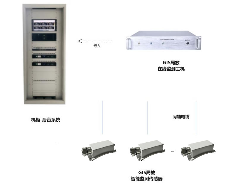
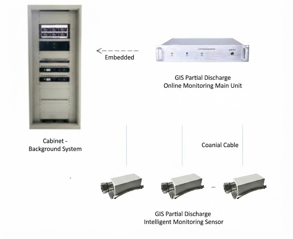
Ang kumpletong pag-install ng GIS PD monitoring ay binubuo ng tatlong layer: mga sensor ng field, isang sentralisadong acquisition at processing host, at backend diagnostic software. Ang arkitektura ay idinisenyo upang ang bawat layer ay gumaganap ng isang partikular na function at walang putol na nakikipag-ugnayan sa susunod.
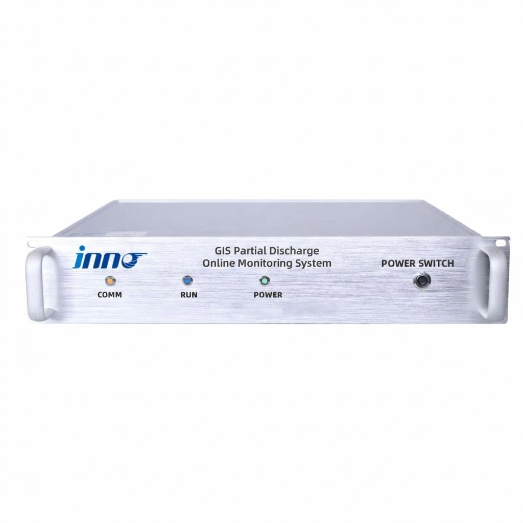
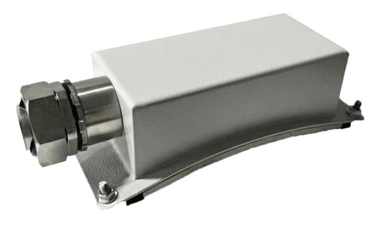
Mga sensor ng UHF ay naka-install sa mga madiskarteng punto sa GIS — karaniwang sa mga spacer joints, mga pagwawakas ng cable, at bushing interface kung saan ang PD ay malamang na magmula. Kinukuha ng bawat sensor ang electromagnetic radiation na ginawa ng mga discharge event at nagpapadala ng signal sa pamamagitan ng coaxial cable sa monitoring host. Ang host ng pagkuha, nakalagay sa isang 2U rack-mount enclosure, tumatanggap ng mga signal mula sa maraming sensor nang sabay-sabay, gumaganap ng high-speed digitization at signal conditioning (demodulasyon, pagbabawas ng ingay, pagpapalakas), at kino-compute ang mga pangunahing parameter ng PD kabilang ang discharge magnitude, anggulo ng phase, and repetition rate. The host then transmits processed data over Ethernet to the backend software platform, which provides real-time visualisation, PRPD pattern analysis, pamamahala ng alarma, makasaysayang trending, and integration with the substation SCADA system.
5. Mga Detalye ng UHF Sensor na Tumutukoy sa Performance ng Detection
The sensor is the first and most critical link in the detection chain. Its specifications directly determine whether the system can detect incipient PD or only advanced faults. The table below details the key parameters of a high-performance UHF sensor designed specifically for GIS applications.
| Parameter | Pagtutukoy | Bakit Ito Mahalaga |
|---|---|---|
| Monitoring Frequency Band | 300 – 3 000 MHz | Covers the full UHF range where GIS PD signals propagate most efficiently inside the metallic enclosure |
| pagiging sensitibo | 5 pC | Detects very small incipient discharges before they escalate to damaging levels |
| Impedance Matching | 50 Oh | Standard RF impedance ensures maximum power transfer from sensor to coaxial cable with minimal reflection loss |
| VSWR (Voltage Standing Wave Ratio) | ≤ 2 | Low standing wave ratio confirms efficient signal transmission; higher VSWR causes signal degradation and measurement error |
| Directivity | Omnidirectional | Equal sensitivity in all directions eliminates the need for precise angular alignment during installation |
| Output Interface | N-type RF connector | Industry-standard connector provides reliable, repeatable connections with low contact resistance |
| Coaxial Cable Length | Pamantayan 10 m (napapasadya) | Accommodates typical distances between GIS and monitoring cabinet; custom lengths available for large installations |
| Operating Temperatura | -40 °C hanggang +85 °C | Supports deployment in extreme climates — from arctic substations to desert environments exceeding 50 °C |
| Humidity Tolerance | ≤ 95 % RH | Rated for tropical and coastal locations with persistent high humidity |
The combination of 5 pC sensitivity and a VSWR of ≤ 2 is particularly important. Sensitivity determines the smallest discharge the system can detect; VSWR determines how much of that signal actually reaches the acquisition host without being reflected back along the cable. A system with high stated sensitivity but poor VSWR will lose a significant fraction of the detected signal in transit, effectively negating its sensitivity advantage.
6. Multi-Channel Acquisition Host — Mga Teknikal na Parameter
The acquisition host is the processing core of the system, responsible for digitising, conditioning, and analysing signals from all connected sensors. The table below presents the core specifications of the monitoring host unit.
| Parameter | Pagtutukoy |
|---|---|
| Dalas ng Pagsubaybay | 300 – 3 000 MHz |
| Bilang ng mga Channel | 4 o 6 (selectable) |
| Mga Interface ng Komunikasyon | RJ45 Ethernet + RS-485 |
| Supported Protocols | Modbus RTU / TCP, IEC 61850, DNP3 |
| Power Supply | AC 90 – 240 V, 50/60 Hz |
| Enclosure | 2U rack-mount (483 mm × 89 mm × 300 mm) |
| Cabinet Protection Rating | IP54 |
| Pagproseso ng Signal | Demodulasyon, isolation, pagbabawas ng ingay, pagpapalakas, high-speed acquisition, multi-cycle periodic measurement |
| Diagnostic Outputs | Maximum discharge magnitude, average discharge magnitude, discharge frequency, 3D PRPD patterns, trend statistics |
Ang pagpili sa pagitan ng 4 at 6 channels depends on the GIS configuration. A single-bay GIS with three compartments can be fully covered by a 4-channel host, while extended bus sections or double-bus arrangements benefit from the additional capacity of a 6-channel unit. The modular channel architecture also means the system can be deployed initially with fewer sensors and expanded later without replacing the host hardware.
7. Pagsusuri ng Pattern ng PRPD — Pagkilala sa Mga Uri ng Discharge sa GIS

Detecting that partial discharge is occurring is only the first step. The real diagnostic value lies in identifying what type of discharge it is, dahil ang bawat uri ay nagpapahiwatig ng ibang mekanismo ng depekto, ibang tindi ng kalubhaan, at ibang tugon sa pagpapanatili.
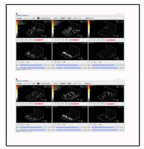
Phase-Resolved Partial Discharge (PRPD) nakakamit ito ng pagsusuri sa pamamagitan ng pagmamapa sa bawat nakitang pulso ng PD sa isang three-dimensional na coordinate system: discharge magnitude sa vertical axis, phase angle ng power-frequency cycle sa horizontal axis, at pulso density na kinakatawan ng kulay o taas. Higit sa daan-daang mga ikot ng kuryente, bawat uri ng discharge ay bumubuo ng isang katangian na pattern.
Corona mula sa mga libreng particle karaniwang tumutuon malapit sa mga taluktok ng boltahe ng isang polarity, na may medyo mababa at pare-parehong magnitude. Paglabas sa ibabaw sa mga spacer gumagawa ng mga asymmetric pattern na kumakalat sa malawak na hanay ng phase, na may pagtaas ng magnitude habang lumalala ang kontaminasyon. Panloob na paglabas ng walang laman within spacer material generates symmetrical patterns on both half-cycles, with relatively stable magnitude that changes little with applied voltage. Floating-potential discharge creates dense, high-magnitude clusters that shift in phase position as the capacitive coupling of the floating component changes with load or temperature.
The monitoring software compares measured PRPD patterns against an expert database of known GIS discharge signatures. When a match is found, the system reports the probable discharge type and recommended action — for example, “free metallic particle detected in compartment B3; recommend inspection at next planned outage” — transforming a complex electromagnetic measurement into a clear maintenance instruction.
8. Backend Software at Pagsasama ng SCADA
The backend software platform runs on the substation control room computer or on a centralised server for multi-site deployments. It provides four core capabilities: real-time monitoring with 3D PRPD visualisation, historical data query and trend analysis, multi-level alarm management with configurable thresholds, and automated report generation for maintenance planning and regulatory compliance.
For integration into the substation automation layer, the monitoring host supports IEC 61850, Modbus RTU/TCP, at DNP3 natively — no external protocol converters are required. Key data points — real-time PD magnitude, alarm status flags, and diagnostic classification codes — are transmitted to the SCADA system, giving dispatchers immediate visibility of GIS insulation health alongside conventional measurements such as bus voltage, kasalukuyang load, and SF₆ gas pressure. This integration enables pagpapanatili batay sa kondisyon at fleet scale: rather than inspecting every GIS compartment on a fixed calendar schedule, maintenance crews are directed to the specific compartments where the monitoring system has identified active or developing PD.
9. Mga Pagsasaalang-alang sa Pag-install at Deployment para sa Mga Kapaligiran ng GIS
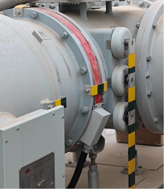
GIS PD monitoring systems are designed for retrofit installation on operational equipment without requiring a GIS outage. UHF sensors are mounted at designated access points on the GIS enclosure — typically at spacer flanges, inspection hatches, or dedicated sensor ports provided by the GIS manufacturer. Coaxial cables route from the sensors to the monitoring cabinet, which can be a standalone IP54-rated enclosure or a panel within the existing relay room.
Several installation practices are critical for reliable performance. Coaxial cables must maintain their minimum bend radius to prevent impedance discontinuities that degrade signal quality. Cable routes should avoid running parallel to high-voltage busbars or power cables to minimise electromagnetic coupling. All equipment grounding connections must be verified, as a poor ground can introduce noise that mimics PD signals. After physical installation, a baseline measurement should be recorded with the GIS in normal service — this baseline becomes the reference against which all future measurements are compared.
A typical installation covering a single GIS bay with 3–4 sensors, one acquisition host, and backend software can be completed in one to two weeks including commissioning, pagkakalibrate, at pagsasanay sa operator.
10. Paano Pumili ng GIS PD Monitoring System — Pamantayan sa Pagpili
Kasama sa merkado ang mga produkto mula sa portable spot-check na mga instrumento hanggang sa ganap na tuluy-tuloy na monitoring platform. Ang mga sumusunod na pamantayan ay tumutulong sa mga mamimili na tumugma sa tamang solusyon sa kanilang partikular na asset ng GIS.
Sensitivity at VSWR
Tumukoy ng sensitivity ng sensor ng 5 pC o mas mahusay at isang VSWR na ≤ 2. Ang dalawang parameter na ito ay magkasamang tumutukoy sa kakayahan sa pagtuklas sa totoong mundo. Isang sensor na may mahusay na nakasaad na sensitivity ngunit isang VSWR ng 3 o mas mataas ay nawawalan ng malaking bahagi ng signal bago ito makarating sa acquisition host.
Sakop ng Dalas
Ang buong 300–3 000 Dapat na sakop ang MHz UHF band. Ang ilang mga sistemang mas mura ay gumagana lamang sa isang makitid na sub-band, na maaaring makaligtaan ang mga lagda ng PD na nagpapakita sa mga frequency sa labas ng window na iyon.
Bilang ng Channel at Pagpapalawak
Pumili ng system na may mapipili 4- o 6-channel na kakayahan at isang modular na arkitektura na nagbibigay-daan sa pagdaragdag ng mga sensor at channel nang hindi pinapalitan ang host unit. Pinoprotektahan nito ang paunang pamumuhunan habang lumalaki ang pag-install ng GIS.
Diagnostic Intelligence
Dapat mag-alok ang system ng 3D PRPD pattern display na may awtomatikong pagtutugma ng pattern laban sa isang ekspertong database. Ang mga system na nag-uulat lamang ng hilaw na amplitude ng signal na walang pag-uuri ng uri ng discharge ay nagbibigay ng pagtuklas ngunit hindi ng diagnosis — at ang diagnosis ang nagtutulak ng mga epektibong desisyon sa pagpapanatili.
Protocol Compatibility
Katutubong suporta para sa protocol ng komunikasyon na naka-deploy na sa substation — IEC 61850, Modbus RTU/TCP, o DNP3 — iniiwasan ang gastos at pagiging maaasahan na panganib ng pagdaragdag ng mga external na converter.
Rating ng Kapaligiran
Dapat ma-rate ang mga sensor para sa buong hanay ng temperatura at halumigmig ng site. For outdoor GIS substations in extreme climates, verify sensor operation from -40 °C hanggang +85 °C and cabinet protection of at least IP54.
Vendor Track Record
Request reference installations in comparable GIS configurations and voltage classes. A vendor with a proven installed base across 110 kV, 220 kV, at 500 kV GIS provides greater confidence in system reliability and technical support capability.
11. Mga Madalas Itanong (FAQ)
Q1: What makes UHF detection better than TEV for GIS partial discharge monitoring?
UHF detection operates in the 300–3 000 MHz range and captures electromagnetic waves propagating inside the sealed GIS enclosure, which acts as a natural shield against external noise. This gives UHF a superior signal-to-noise ratio compared to TEV, which measures transient voltage pulses on the external enclosure surface and is more exposed to ambient electromagnetic interference. UHF also provides higher sensitivity to internal defects and better capability for discharge type classification through PRPD pattern analysis. TEV remains useful as a portable screening tool, but for permanent online monitoring of GIS, UHF is the technically superior choice.
Q2: How many UHF sensors are needed per GIS bay?
The recommended practice is one sensor per GIS compartment for comprehensive coverage. For a typical single-bay arrangement this means 3–4 sensors covering the bus compartments and cable termination. Ang mga kritikal na bay o bay na may kasaysayan ng mga isyu sa pagkakabukod ay maaaring maggarantiya ng karagdagang mga sensor sa mga kilalang mahinang punto gaya ng mga spacer joint at bushing interface. A 4- o 6-channel acquisition host ay tinatanggap ang mga configuration na ito nang walang kahirapan.
Q3: Maaari bang makilala ng system ang mga uri ng PD sa loob ng GIS?
Oo. Gumagamit ang system ng 3D PRPD pattern analysis upang uriin ang mga kaganapan sa paglabas sa apat na kategorya: corona discharge mula sa mga libreng metal na particle, paglabas sa ibabaw sa mga kontaminadong spacer, internal void discharge sa loob ng solid insulation, at lumulutang-potensyal na paglabas mula sa hindi pinagbabatayan na mga bahaging metal. Ang bawat uri ay gumagawa ng isang katangian ng phase-magnitude pattern na ang software ay tumutugma sa isang dalubhasang database para sa awtomatikong pagkilala.
Q4: Nangangailangan ba ang pag-install ng pagkawala ng GIS?
Hindi. UHF sensors are mounted at external access points on the GIS enclosure — spacer flanges, mga port ng inspeksyon, or dedicated sensor windows — without opening any gas compartments. Coaxial cables are routed to the monitoring cabinet, which is installed in a nearby relay room or standalone enclosure. The entire installation, including commissioning and baseline measurement, is performed with the GIS energised and in normal service.
Q5: How does the system handle false alarms in electrically noisy substations?
The GIS metallic enclosure provides natural electromagnetic shielding that inherently rejects most external interference in the UHF band. Beyond this physical advantage, the acquisition host applies frequency-domain filtering, time-domain gating, and pattern-recognition algorithms to distinguish genuine PD pulses from transient disturbances. Adjustable alarm thresholds can be tuned to the site-specific background noise level during commissioning. These combined measures typically achieve PD detection accuracy above 95 % with false alarm rates below 2 %.
Q6: What SCADA protocols does the system support?
The monitoring host provides RJ45 Ethernet and RS-485 interfaces with native support for Modbus RTU, Modbus TCP, IEC 61850, at DNP3. This covers virtually every substation automation architecture in use today and ensures that PD data — including real-time discharge magnitude, katayuan ng alarma, and diagnostic codes — can be transmitted directly to the SCADA master station without external protocol converters.
Q7: What is the expected return on investment?
A single prevented GIS compartment failure — which can cost several million dollars in equipment replacement, emergency repair, and lost revenue from extended outage — typically justifies the entire monitoring system investment. Additional ROI sources include reduced maintenance costs through the shift from time-based to condition-based inspection, extended GIS service life through early intervention, and reduced insurance premiums. Most installations achieve full ROI within two to three years.
Q8: Can the system be expanded after the initial installation?
Oo. The modular architecture allows additional sensors to be added to new GIS compartments and connected to spare channels on the existing acquisition host. If all channels are occupied, an additional host unit can be installed and connected to the same backend software platform. Multiple GIS bays, or even multiple substations, can be monitored from a single centralised software interface, pagbibigay ng fleet-wide visibility ng GIS insulation health.
Disclaimer: Ang impormasyong ibinigay sa artikulong ito ay para sa pangkalahatang layuning pang-edukasyon at sanggunian lamang. FJINNO (www.fjinno.net) walang garantiya, ipinahayag o ipinahiwatig, tungkol sa pagkakumpleto, katumpakan, o pagiging angkop ng nilalaman sa anumang partikular na proyekto o pag-install. Ang mga teknikal na pagtutukoy na isinangguni dito ay kumakatawan sa mga tipikal na halaga at maaaring mag-iba depende sa uri ng GIS, paglalagay ng sensor, at kapaligiran ng site. Ang mga desisyon sa engineering ay dapat palaging nakabatay sa mga pagtatasa na partikular sa site na isinagawa ng mga kwalipikadong propesyonal alinsunod sa mga naaangkop na pamantayan kabilang ang IEC 62478, IEC 61850, at mga lokal na grid code. Ang mga pangalan ng produkto ng mga tagagawa ng third-party ay mga trademark ng kani-kanilang mga may-ari at binanggit para sa impormasyong sanggunian lamang. Ang FJINNO ay hindi mananagot para sa anumang pagkawala o pinsala na dulot ng paggamit o pag-asa sa impormasyong ito.

Sensor ng temperatura ng fiber optic, Intelligent na sistema ng pagsubaybay, Ibinahagi ang tagagawa ng fiber optic sa China
 |
 |
 |