 INNO เซ็นเซอร์วัดอุณหภูมิใยแก้วนำแสง ,ระบบตรวจสอบอุณหภูมิ.
- ความร้อนสูงเกินไปของหม้อแปลงเป็นสาเหตุส่วนใหญ่ของความล้มเหลวของฉนวนก่อนกำหนดและการหยุดทำงานโดยไม่คาดคิดในเครือข่ายไฟฟ้าทั่วโลก ทำให้การตรวจสอบอุณหภูมิเป็นหนึ่งในการลงทุนที่มีมูลค่าสูงสุดในการปกป้องทรัพย์สิน.
- เทคโนโลยีการตรวจสอบอุณหภูมิหม้อแปลงหลักห้าประการ ได้แก่: fluorescent fiber optic thermometry, PT100 เครื่องตรวจจับอุณหภูมิความต้านทาน, ตัวบ่งชี้อุณหภูมิน้ำมันจำลองความร้อน, เซ็นเซอร์อุณหภูมิไร้สาย, และ เทอร์โมกราฟฟีอินฟราเรด.
- เซนเซอร์ไฟเบอร์ออปติกฟลูออเรสเซนต์ เป็นเทคโนโลยีเดียวที่สามารถวัดจุดร้อนที่คดเคี้ยวโดยตรงภายในหม้อแปลงไฟฟ้าที่มีการป้องกัน EMI เต็มรูปแบบและความแม่นยำ ±0.5°C ทำให้เป็นมาตรฐานทองคำสำหรับสินทรัพย์ไฟฟ้าแรงสูงที่สำคัญ.
- เซ็นเซอร์ PT100 เป็นเทอร์โมมิเตอร์แบบสัมผัสมาตรฐานอุตสาหกรรมสำหรับการตรวจสอบอุณหภูมิน้ำมันและระบบทำความเย็นระดับสูงสุด, บูรณาการอย่างกว้างขวางในรีเลย์ป้องกันหม้อแปลงและระบบ SCADA.
- ตัวบ่งชี้อุณหภูมิน้ำมันจำลองความร้อน คำนวณอุณหภูมิจุดร้อนของขดลวดโดยประมาณโดยใช้แบบจำลองความร้อนแบบอะนาล็อกของคุณลักษณะการเพิ่มความร้อนของหม้อแปลง - โซลูชันที่คุ้มค่าสำหรับการป้องกันตามปกติของหม้อแปลงไฟฟ้าระบบจำหน่าย.
- เซ็นเซอร์วัดอุณหภูมิแบบไร้สาย ให้การตรวจสอบหลายจุดโดยไม่ต้องใช้สายเคเบิลบนพื้นผิวหม้อแปลง, บูช, และการสิ้นสุดสายเคเบิล — เหมาะสำหรับการติดตั้งเพิ่มเติมและเปลือกหม้อแปลงชนิดแห้ง.
- เทอร์โมกราฟฟีอินฟราเรด ให้ภาพแผนที่ความร้อนแบบไม่สัมผัสสำหรับการตรวจสอบการบำรุงรักษาตามกำหนดเวลา แต่ไม่สามารถให้การแจ้งเตือนแบบเรียลไทม์อย่างต่อเนื่องแบบที่ระบบตรวจสอบออนไลน์นำเสนอได้.
- โซลูชันการตรวจสอบอุณหภูมิหม้อแปลงที่ดีที่สุดผสมผสานการตรวจจับจุดร้อนที่ขดลวดโดยตรงกับการวัดอุณหภูมิน้ำมันระดับสูงสุด, การจัดการสัญญาณเตือนแบบหลายชั้น, และการบูรณาการกับแพลตฟอร์ม SCADA หรือ EMS ที่มีอยู่.
1. หม้อแปลงไฟฟ้ากำลังคืออะไร? กระดูกสันหลังของโครงข่ายไฟฟ้าทุกระบบ

ก หม้อแปลงไฟฟ้า เป็นอุปกรณ์แม่เหล็กไฟฟ้าแบบคงที่ที่ถ่ายโอนพลังงานไฟฟ้าระหว่างสองวงจรขึ้นไปผ่านการเหนี่ยวนำแม่เหล็กไฟฟ้า, ปรับแรงดันไฟฟ้าขึ้นหรือลงพร้อมกันเพื่อให้ตรงกับความต้องการของระบบส่งกำลัง, การกระจาย, หรืออุปกรณ์ใช้งานปลายทาง. หม้อแปลงไฟฟ้าเป็นรากฐานสำคัญของระบบไฟฟ้ากระแสสลับทุกระบบ ตั้งแต่การผลิตระดับสาธารณูปโภคและเครือข่ายการส่งไฟฟ้าแรงสูงไปจนถึงจุดจำหน่ายขั้นสุดท้ายในอาคารพาณิชย์, โรงงานอุตสาหกรรม, หรือย่านที่อยู่อาศัย.
ประเภทหลักของหม้อแปลงไฟฟ้ากำลัง
หม้อแปลงไฟฟ้ากำลังแช่น้ำมัน เป็นเทคโนโลยีที่โดดเด่นสำหรับการใช้งานไฟฟ้าแรงสูงและความจุสูง. แกนกลางและขดลวดจุ่มอยู่ในน้ำมันแร่, ซึ่งทำหน้าที่เป็นทั้งฉนวนไฟฟ้าและเป็นสื่อทำความเย็นหลัก. หน่วยเหล่านี้พบได้ในสถานีส่งไฟฟ้าย่อย, สิ่งอำนวยความสะดวกทางอุตสาหกรรม, และการเชื่อมต่อพลังงานหมุนเวียนในระดับกริดตั้งแต่ MVA ไม่กี่ MVA ไปจนถึงมากกว่านั้น 1,000 เอ็มวีเอ.
หม้อแปลงชนิดแห้ง ใช้ฉนวนคาสเรซินแข็งแทนน้ำมัน, ลดความเสี่ยงจากไฟไหม้และทำให้เป็นตัวเลือกที่ต้องการสำหรับการติดตั้งภายในอาคาร เช่น ศูนย์ข้อมูล, โรงพยาบาล, อาคารสูงเชิงพาณิชย์, สถานีรถไฟใต้ดิน, และโรงงานเซมิคอนดักเตอร์. ยูนิตแบบแห้งแบบหล่อเรซินทำงานที่แรงดันไฟฟ้าและพิกัดพลังงานต่ำกว่ายูนิตที่เติมน้ำมัน แต่ต้องใช้โดยตรง การตรวจสอบอุณหภูมิที่คดเคี้ยว เนื่องจากความไวต่อความร้อนที่สูงขึ้น.
หม้อแปลงไฟฟ้าหุ้มฉนวนแก๊ส ใช้ซัลเฟอร์เฮกซาฟลูออไรด์ (เอสเอฟ₆) หรือไนโตรเจนเป็นตัวกลางในการเป็นฉนวนและความเย็น. ใช้ในการใช้งานที่ต้องการพื้นที่ขนาดเล็ก, ความไวไฟต่ำ, และความน่าเชื่อถือสูง — รวมถึงแพลตฟอร์มนอกชายฝั่ง, สถานีย่อย GIS ในเมือง, และโครงสร้างพื้นฐานที่สำคัญ.
หม้อแปลงไฟฟ้าแบบติดแผ่นและแบบกล่อง เป็นหน่วยจำหน่ายแบบครบวงจรที่ใช้สำหรับการแปลงแรงดันปานกลางเป็นแรงดันต่ำที่จุดบริการเชิงพาณิชย์และที่อยู่อาศัย, ครบครันยิ่งขึ้นด้วยการบูรณาการ smart transformer monitoring systems สำหรับการจัดการสภาพระยะไกล.
อุตสาหกรรมขึ้นอยู่กับความน่าเชื่อถือของหม้อแปลง
การทำงานของหม้อแปลงที่เชื่อถือได้ถือเป็นสิ่งสำคัญอย่างยิ่งต่อระบบสาธารณูปโภคด้านไฟฟ้า, น้ำมันและก๊าซ, การผลิตยานยนต์, การขนส่งทางรถไฟ, ศูนย์ข้อมูล, การทำเหมืองแร่, ปิโตรเคมี, และการดูแลสุขภาพ. ความล้มเหลวเนื่องจากความร้อนในหม้อแปลงไฟฟ้าขนาดใหญ่อาจส่งผลให้ต้องใช้เวลาซ่อมแซมหลายสัปดาห์, ต้นทุนทดแทนทุนที่สำคัญ, และผลกระทบต่อเนื่องต่อเสถียรภาพของโครงข่ายไฟฟ้าและการดำเนินงานด้านสิ่งอำนวยความสะดวก.
2. ภายในถัง: ส่วนประกอบหลักของหม้อแปลงชนิดแช่น้ำมันและชนิดแห้ง

การทำความเข้าใจการก่อสร้างหม้อแปลงเป็นสิ่งสำคัญสำหรับการออกแบบที่มีประสิทธิภาพ กลยุทธ์การตรวจสอบอุณหภูมิหม้อแปลงไฟฟ้า. ส่วนประกอบหลักแต่ละชิ้นมีลักษณะเฉพาะด้านความร้อนและโหมดความล้มเหลวที่แตกต่างกัน ซึ่งเป็นตัวกำหนดตำแหน่งและวิธีวางเซ็นเซอร์.
ขดลวด (คอยส์)

ที่ ขดลวดหม้อแปลง เป็นส่วนประกอบที่มีความสำคัญต่อความร้อนมากที่สุด. ตัวนำทองแดงหรืออะลูมิเนียมมีกระแสโหลดเต็มและสร้างความร้อนต้านทาน (การสูญเสียI²R) ที่ต้องกระจายออกไปอย่างต่อเนื่อง. ที่ จุดที่คดเคี้ยว - จุดอุณหภูมิสูงสุดจุดเดียวภายในขดลวด - เป็นตัวกำหนดหลักของอายุการใช้งานของฉนวนหม้อแปลงและความสามารถในการรับน้ำหนัก. ไออีซี 60076-2 กำหนดวิธีการวัดและการคำนวณแบบฮอตสปอตที่สนับสนุนความทันสมัยทั้งหมด มาตรฐานการป้องกันความร้อนของหม้อแปลงไฟฟ้า.
แกนกลาง (Iron Core)

แกนเหล็กซิลิคอนเคลือบนำพาฟลักซ์แม่เหล็กสลับและสร้างกระแสเอ็ดดี้และการสูญเสียฮิสเทรีซีสที่ปรากฏเมื่อความร้อนกระจายไปทั่วปริมาตรแกนกลาง. จุดร้อนหลักเฉพาะจุดที่เกิดจากความเสียหายของฉนวนระหว่างชั้น, กระแสหมุนเวียน, หรือข้อบกพร่องในการผลิตอาจทำให้เกิดเหตุการณ์ความร้อนภายในที่ยากต่อการตรวจจับหากไม่มีการตรวจจับไฟเบอร์แบบกระจาย.
น้ำมันฉนวน
ในหม้อแปลงไฟฟ้าที่เติมน้ำมัน, น้ำมันแร่หรือน้ำมันเอสเทอร์สังเคราะห์ทำหน้าที่เป็นทั้งตัวกลางฉนวนหลักและของเหลวถ่ายเทความร้อนแบบพาความร้อน. อุณหภูมิน้ำมันสูงสุด เป็นพารามิเตอร์หม้อแปลงที่มีการตรวจสอบอย่างกว้างขวางที่สุด, measured by เซ็นเซอร์ PT100 หรือ ตัวบ่งชี้การจำลองความร้อน ติดตั้งบนถังหม้อแปลง. การเสื่อมสภาพของน้ำมัน — วัดจากความเป็นกรด, การวิเคราะห์ก๊าซละลาย (ดีจีเอ), และปริมาณความชื้น — เร่งความเร็วให้สูงกว่าอุณหภูมิในการทำงานที่กำหนดอย่างมาก.
แตะตัวเปลี่ยน

ที่ ตัวเปลี่ยนการแตะขณะโหลด (โอแอลทีซี) เป็นส่วนประกอบทางกลไกที่ซับซ้อนที่สุดของหม้อแปลงไฟฟ้ากำลังและเป็นแหล่งกำเนิดชั้นนำของข้อผิดพลาดทางความร้อน. การสึกหรอของหน้าสัมผัส, การปนเปื้อนของคาร์บอน, และน้ำมันที่ไม่ถูกต้องส่งผลให้มีความต้านทานการเปลี่ยนผ่านสูงขึ้นและความร้อนเฉพาะที่บริเวณหน้าสัมผัสตัวเลือกก๊อกน้ำ — โหมดความผิดปกติที่ตรวจพบได้โดยตรง เซนเซอร์วัดอุณหภูมิใยแก้วนำแสงแบบฝัง.
บูช

ไฟฟ้าแรงสูง บูชหม้อแปลง นำกระแสผ่านผนังถังและอาจได้รับความร้อนจากอิเล็กทริก, ความต้านทานการสัมผัสที่จุดเชื่อมต่อเทอร์มินัล, และความชื้นเข้า. ฮอตสปอตบุชชิ่งได้รับการตรวจสอบอย่างมีประสิทธิภาพโดยใช้ เครื่องส่งสัญญาณอุณหภูมิไร้สาย หรือการตรวจสอบด้วยอินฟราเรดผ่านหน้าต่างสังเกตการณ์ที่กำหนด.
Cooling System
หม้อแปลงที่แช่น้ำมันจะถูกระบายความร้อนโดยการหมุนเวียนของน้ำมันตามธรรมชาติหรือแบบบังคับรวมกับธนาคารหม้อน้ำ, แฟน ๆ, หรือเครื่องแลกเปลี่ยนความร้อนของน้ำ. การตรวจสอบประสิทธิภาพระบบทำความเย็น — รวมถึงความแตกต่างของอุณหภูมิทางเข้า/ทางออกของหม้อน้ำที่วัดโดยเซ็นเซอร์ PT100 — เป็นส่วนประกอบมาตรฐานของ ระบบการจัดการความร้อนของหม้อแปลงไฟฟ้า.
3. ทำไม Transformers ถึงล้มเหลว? สาเหตุหลักของความผิดปกติทางความร้อนในหม้อแปลงไฟฟ้ากำลัง
การสำรวจในอุตสาหกรรมระบุอย่างต่อเนื่องว่าการเสื่อมสภาพจากความร้อนเป็นสาเหตุหลักของความล้มเหลวของฉนวนหม้อแปลงและการหมดอายุการใช้งานก่อนเวลาอันควร. ตามการศึกษาความน่าเชื่อถือของ CIGRE และ IEEE, ความผิดปกติของความร้อนคิดเป็น 30–40% ของความล้มเหลวของหม้อแปลงหลักทั้งหมด — สัดส่วนที่เพิ่มขึ้นอีกเมื่อระบบทำความเย็นล้มเหลวและเหตุการณ์โอเวอร์โหลดถูกรวมไว้ในการวิเคราะห์.
คดเคี้ยว
การโอเวอร์โหลดอย่างต่อเนื่องจะทำให้อุณหภูมิของขดลวดสูงกว่าขีดจำกัดความร้อนที่กำหนดโดยชั้นฉนวน. สำหรับหม้อแปลงน้ำมันแร่มาตรฐานที่มีคลาส A (105องศาเซลเซียส) ฉนวนเซลลูโลส, การทำงานที่อุณหภูมิ 10°C เหนือขีดจำกัดฮอตสปอตที่กำหนดจะช่วยลดอายุการใช้งานของฉนวนที่คาดหวังลงครึ่งหนึ่ง - ความสัมพันธ์ที่ควบคุมโดย แบบจำลองการชราภาพด้วยความร้อนของ Arrhenius ประมวลผลใน IEC 60076-7.
Cooling System Failure
มอเตอร์พัดลมทำงานผิดปกติ, ครีบหม้อน้ำที่ถูกบล็อก, ปั๊มทำงานผิดปกติ, และการทำงานผิดพลาดของวาล์วน้ำมันล้วนลดความสามารถของหม้อแปลงในการกระจายความร้อน. หม้อแปลงไฟฟ้าที่ทำงานโดยระบบระบายความร้อนที่ล้มเหลวโดยสิ้นเชิงสามารถเข้าถึงอุณหภูมิขดลวดที่สำคัญได้ภายใน 30–60 นาทีภายใต้โหลดเต็ม ซึ่งเป็นสถานการณ์ที่ต้องการ การตรวจสอบจุดร้อนที่คดเคี้ยวอย่างต่อเนื่องแบบเรียลไทม์ พร้อมการลดภาระหรือการป้องกันการเดินทางอัตโนมัติ.
แตะตัวเปลี่ยนการติดต่อเสื่อมโทรม
OLTC ทำงานภายใต้ภาระงาน, การสร้างอาร์คหน้าสัมผัสที่จะค่อยๆ ลดระดับหน้าสัมผัสของตัวเลือกและปนเปื้อนน้ำมันไดเวอร์เตอร์. As contact resistance increases, ความร้อนในท้องถิ่นเพิ่มขึ้นตามสัดส่วน. การศึกษาระบุว่า ข้อบกพร่องที่เกี่ยวข้องกับ OLTC account for approximately 40% ของความล้มเหลวของหม้อแปลงทั้งหมดที่ต้องมีการซ่อมแซมครั้งใหญ่ - หมวดหมู่ความล้มเหลวที่ใหญ่ที่สุดตามสาเหตุ.
โอเวอร์โหลดและการทำงานฉุกเฉิน
เหตุการณ์ฉุกเฉินกริด, อุปกรณ์ขัดข้อง, และการเติบโตของโหลดที่ผิดปกติจะผลักดันหม้อแปลงไฟฟ้าระบบจำหน่ายและหม้อแปลงไฟฟ้าให้อยู่สูงกว่าพิกัดของแผ่นป้ายเป็นประจำ. ในขณะที่หม้อแปลงสามารถทนต่อการโอเวอร์โหลดระยะสั้นตาม IEC 60076-7 กำลังโหลดคำแนะนำ, เหตุการณ์โอเวอร์โหลดแต่ละครั้งจะใช้ส่วนที่วัดได้ของอายุฉนวนที่เหลืออยู่ซึ่งไม่สามารถกู้คืนได้.
ข้อบกพร่องของฉนวนแกนกลาง
ความเสียหายของฉนวนแกนกลางระหว่างชั้นทำให้เกิดเส้นทางที่มีความต้านทานต่ำสำหรับการไหลเวียนของกระแสไหลวน, สร้างความร้อนเข้มข้นในบริเวณแกนกลางที่มีการแปลเป็นภาษาท้องถิ่น. ข้อบกพร่องเหล่านี้ ซึ่งมักเกิดจากความเสียหายทางกลระหว่างการขนส่งหรือการติดตั้ง สามารถทำให้เกิดจุดร้อนภายในอย่างต่อเนื่อง ซึ่งเร่งการเสื่อมสภาพของน้ำมัน และสร้างก๊าซที่ติดไฟได้ละลายซึ่งตรวจพบได้โดยการตรวจสอบ DGA.
4. ต้นทุนที่แท้จริงของหม้อแปลงร้อนจัด: ความเสี่ยงและผลที่ตามมา
ผลที่ตามมาของความไม่เพียงพอ การตรวจสอบอุณหภูมิหม้อแปลง ขยายออกไปไกลเกินกว่าตัวหม้อแปลงเอง. ความล้มเหลวของหม้อแปลงหลักเพียงตัวเดียวในโรงงานที่สำคัญสามารถกระตุ้นให้เกิดห่วงโซ่การปฏิบัติงานได้, การเงิน, ความปลอดภัย, และผลที่ตามมาด้านกฎระเบียบที่ต้องใช้เวลาหลายเดือนในการแก้ไขอย่างสมบูรณ์.
การเร่งอายุของฉนวนและอายุสินทรัพย์ที่ลดลง
ฉนวนกระดาษเซลลูโลส — วัสดุอิเล็กทริกปฐมภูมิในหม้อแปลงที่แช่น้ำมัน — ผ่านการย่อยสลายเนื่องจากความร้อนที่ไม่สามารถกลับคืนสภาพเดิมได้ผ่านกระบวนการทางเคมีที่อธิบายโดย สมการอาร์รีเนียส. ทุกๆ 6–10°C ของอุณหภูมิจุดหมุนของขดลวดจะสูงกว่าขีดจำกัดการออกแบบที่กำหนด, อายุการใช้งานที่คาดหวังของหม้อแปลงไฟฟ้าจะลดลงประมาณครึ่งหนึ่ง. หม้อแปลงไฟฟ้าที่ออกแบบให้มีอายุการใช้งาน 40 ปีสามารถมีอายุก่อนกำหนดจนถึงสิ้นสุดอายุการใช้งานได้ภายใต้ 15 หลายปีผ่านการทำงานที่อุณหภูมิเกินปานกลางอย่างต่อเนื่องซึ่งจะตรวจไม่พบหากไม่มี การวัดอุณหภูมิของขดลวดโดยตรง.
ความล้มเหลวอย่างหายนะ, Fire, และความเสี่ยงจากการระเบิด
ความร้อนสูงเกินไปของขดลวดอย่างรุนแรงทำให้เกิดการเสื่อมสภาพของน้ำมันอย่างรวดเร็ว, การสร้างก๊าซ, และเกิดอาร์คภายในที่อาจเกิดขึ้น. ในหม้อแปลงไฟฟ้าที่เติมน้ำมัน, การรวมกันของอาร์คไฟฟ้าและไอน้ำมันไฮโดรคาร์บอนทำให้เกิดเงื่อนไข tank rupture, ไฟน้ำมัน, และการปล่อยแรงดันระเบิด. ไฟไหม้หม้อแปลงไฟฟ้าครั้งใหญ่ในสถานีไฟฟ้าย่อยและโรงงานอุตสาหกรรมส่งผลให้มีผู้เสียชีวิต, การทำลายโครงสร้าง, และเหตุการณ์การปนเปื้อนที่ต้องการการฟื้นฟูสิ่งแวดล้อมมูลค่าหลายล้านดอลลาร์. ความล้มเหลวของหม้อแปลงชนิดแห้ง, ในขณะที่เสี่ยงต่อการเกิดเพลิงไหม้น้อยกว่า, สามารถผลิตควันพิษจากการเผาเรซินหล่อ และทำให้เกิดการปิดโรงงานเป็นเวลานาน.
การหยุดทำงานโดยไม่ได้วางแผนและการสูญเสียการผลิต
หม้อแปลงไฟฟ้ากำลังขนาดใหญ่ที่ระดับแรงดันการส่ง (138กิโลโวลต์ขึ้นไป) โดยทั่วไปจะมีระยะเวลารอคอยสินค้าประมาณ 12–24 เดือนในการเปลี่ยน. ความล้มเหลวโดยไม่ได้วางแผนไว้ของหม้อแปลงที่มีความสำคัญต่อกริดอาจส่งผลให้การหยุดชะงักของอุปทานขยายออกไปซึ่งส่งผลกระทบต่อลูกค้าอุตสาหกรรม, สาธารณูปโภค, และชุมชน. สำหรับโรงงานผลิต, ศูนย์ข้อมูล, และโรงพยาบาล, ค่าใช้จ่ายของการไฟฟ้าดับโดยไม่ได้วางแผนโดยทั่วไปจะอยู่ในช่วงตั้งแต่หลายหมื่นถึงหลายล้านดอลลาร์ต่อชั่วโมงของการหยุดทำงาน — ทำให้เศรษฐศาสตร์ของ การตรวจสอบหม้อแปลงแบบคาดการณ์ น่าสนใจในทุกระดับการใช้งาน.
การปฏิบัติตามกฎระเบียบและผลกระทบจากการประกันภัย
Utility regulators, ผู้จัดการการจัดจำหน่ายประกันภัย, และหน่วยงานมาตรฐานอุปกรณ์จำเป็นต้องมีหลักฐานการตรวจสอบสภาพความร้อนสำหรับหม้อแปลงไฟฟ้าที่สูงกว่าเกณฑ์ MVA ที่กำหนดไว้เพิ่มมากขึ้น. สิ่งอำนวยความสะดวกที่ไม่สามารถแสดงออกถึงความกระตือรือร้นได้ โปรแกรมตรวจสอบอุณหภูมิหม้อแปลง อาจต้องเผชิญกับเบี้ยประกันที่เพิ่มขึ้น, ลดความคุ้มครองสำหรับการเรียกร้องความล้มเหลวเนื่องจากความร้อน, หรือการละเมิดการปฏิบัติตามมาตรฐานความน่าเชื่อถือของผู้ปฏิบัติงานโครงข่ายไฟฟ้า เช่น NERC TPL และ IEC 60076 ชุด.
5. ความร้อนเข้มข้นอยู่ที่ไหน? ตำแหน่งฮอตสปอตที่สำคัญในหม้อแปลงไฟฟ้ากำลัง
มีประสิทธิภาพ การตรวจจับฮอตสปอตของหม้อแปลง จำเป็นต้องมีความเข้าใจอย่างแม่นยำว่าความเครียดจากความร้อนสะสมที่ใดภายใต้สภาวะการทำงานปกติและผิดปกติ. ตำแหน่งต่อไปนี้แสดงถึงโซนเสี่ยงต่อความร้อนสูงสุดในทั้งสองแห่ง หม้อแปลงไฟฟ้ากำลังแบบจุ่มน้ำมันและแบบแห้ง และควรเป็นพื้นฐานของแผนการจัดวางเซ็นเซอร์.
Winding Hot Spot — จุดตรวจสอบที่สำคัญที่สุด
ที่ จุดที่คดเคี้ยว ถูกกำหนดโดย IEC 60076-2 เป็นจุดอุณหภูมิสูงสุดภายในชุดขดลวดหม้อแปลง - โดยทั่วไปจะอยู่ที่หนึ่งในสามด้านบนของขดลวดแรงดันต่ำหรือแรงดันสูง โดยความหนาแน่นกระแสและข้อจำกัดการไหลของน้ำมันรวมกันเพื่อสร้างการสะสมความร้อนสูงสุด. อุณหภูมิจุดร้อนจะควบคุมอัตราการเสื่อมสภาพของฉนวนโดยตรง และเป็นพารามิเตอร์หลักที่ใช้ในการคำนวณอายุการใช้งานของหม้อแปลงที่เหลืออยู่และความจุเกินที่อนุญาต. การวัดอุณหภูมิจุดร้อนของขดลวดโดยตรงโดยใช้ หัววัดไฟเบอร์ออปติกฟลูออเรสเซนต์แบบฝัง เป็นวิธีเดียวที่ให้ความจริง, การอ่านค่าพารามิเตอร์ที่สำคัญนี้แบบเรียลไทม์ แทนที่จะใช้ค่าประมาณที่คำนวณได้.
อุณหภูมิน้ำมันสูงสุด
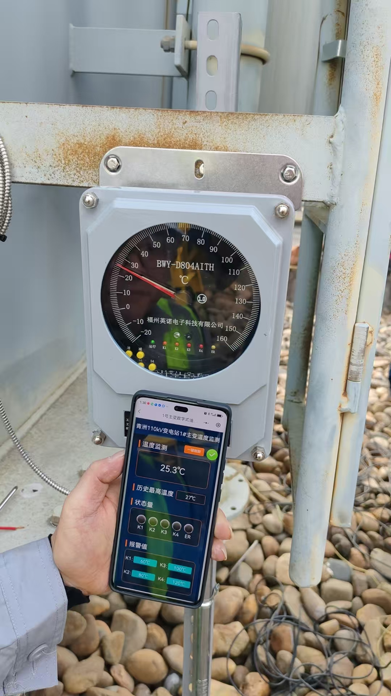
อุณหภูมิน้ำมันสูงสุด เป็นพารามิเตอร์หม้อแปลงที่ได้รับการตรวจสอบอย่างกว้างขวางที่สุดในการให้บริการในปัจจุบัน, measured by PT100 เครื่องตรวจจับอุณหภูมิความต้านทาน หรือ ตัวบ่งชี้อุณหภูมิน้ำมันจำลองความร้อน ติดตั้งในฝาครอบถังหม้อแปลงหรือท่ออนุรักษ์. ในขณะที่อุณหภูมิน้ำมันสูงสุดไม่สามารถวัดสภาวะจุดร้อนของขดลวดได้โดยตรง, โดยให้ข้อบ่งชี้ที่เชื่อถือได้เกี่ยวกับภาระความร้อนและประสิทธิภาพของระบบทำความเย็นโดยรวม, และทำหน้าที่เป็นอินพุตหลักสำหรับอัลกอริธึมการคำนวณฮอตสปอตการจำลองความร้อนที่ใช้ในการตั้งค่ารีเลย์ป้องกัน.
จุดร้อนที่มีการแปลแกนเหล็ก
จุดร้อนหลักที่เกิดจากความเสียหายของฉนวนระหว่างชั้น, การเคลือบแบบสั้น, หรือความเข้มข้นของฟลักซ์จรจัดสามารถสร้างความร้อนเฉพาะที่อย่างยั่งยืน ซึ่งเร่งการเสื่อมสภาพของน้ำมันและก่อให้เกิดก๊าซที่ติดไฟได้ละลาย ซึ่งเป็นสัญญาณแรกสุดที่ตรวจพบได้ของความผิดปกติของความร้อนแกนกลางที่เริ่มเกิดขึ้น. เซ็นเซอร์ที่ติดตั้งบนพื้นผิวไม่สามารถเข้าถึงฮอตสปอตภายในเหล่านี้ได้ และจำเป็นต้องมีอย่างใดอย่างหนึ่ง การตรวจจับใยแก้วนำแสงแบบกระจาย ภายในส่วนประกอบหลักหรือการตรวจจับทางอ้อมผ่านการวิเคราะห์ก๊าซละลาย (ดีจีเอ) การตรวจสอบ.
รายชื่อผู้ติดต่อ Tap Changer เมื่อโหลด
ที่ หน้าสัมผัสสวิตช์ไดเวอร์เตอร์ OLTC ทำงานภายใต้กระแสโหลดเต็มและอาจเกิดการสึกหรอจากการสัมผัสและความต้านทานเพิ่มขึ้น. ความต้านทานต่อการสัมผัสที่เพิ่มขึ้นจะสร้างความร้อนเฉพาะจุดภายในช่องเปลี่ยนก๊อกน้ำซึ่งสามารถตรวจจับได้ หัววัดอุณหภูมิแบบไฟเบอร์ออปติกแบบฝัง หรือเซ็นเซอร์ไร้สายที่ติดตั้งอยู่ภายในตัวเรือน OLTC โดยจะแจ้งเตือนล่วงหน้าถึงการเสื่อมสภาพของหน้าสัมผัสก่อนที่จะดำเนินไปสู่เหตุการณ์ความล้มเหลวของไดเวอร์เตอร์.
การเชื่อมต่อเทอร์มินัลบูช
ขั้วต่อบุชชิ่งไฟฟ้าแรงสูง อาจมีความเครียดจากความร้อนจากการสูญเสียอิเล็กทริกภายในคอนเดนเซอร์แบบบุชชิ่งและความต้านทานการสัมผัสที่แคลมป์ขั้วต่อภายนอก. การเชื่อมต่อขั้วต่อที่หลวมหรือสึกกร่อนจะสร้างความร้อนที่พื้นผิวเฉพาะจุดซึ่งสามารถตรวจจับได้อย่างมีประสิทธิภาพ เครื่องส่งสัญญาณอุณหภูมิไร้สาย ยึดเข้ากับขั้วต่อเทอร์มินัลหรือตามระยะ การตรวจสอบความร้อนด้วยอินฟราเรด ระหว่างการหยุดซ่อมบำรุงตามกำหนด.
จุดเข้าและทางออกของระบบทำความเย็น
ความแตกต่างของอุณหภูมิระหว่างทางเข้าหม้อน้ำ (น้ำมันร้อน) และทางออก (น้ำมันเย็น) ให้การวัดประสิทธิภาพระบบทำความเย็นโดยตรง. เซ็นเซอร์ PT100 ติดตั้งที่ท่อทางเข้าและทางออกของหม้อน้ำช่วยให้สามารถตรวจสอบประสิทธิภาพการกระจายความร้อนได้อย่างต่อเนื่อง โดยตรวจจับการอุดตันบางส่วน, fan failures, และการเสื่อมสภาพของปั๊มก่อนที่จะทำให้เกิดอุณหภูมิของขดลวดเกิน.
การสิ้นสุดสายเคเบิลและการเชื่อมต่อ LV Busbar
ข้อต่อบัสบาร์แรงดันต่ำและการสิ้นสุดสายเคเบิลที่เทอร์มินัลรองของหม้อแปลงไฟฟ้ามีกระแสไฟฟ้าสูงและมีแนวโน้มที่จะเพิ่มความต้านทานการสัมผัสจากการเชื่อมต่อที่หลวม, ออกซิเดชัน, และความเหนื่อยล้าจากการปั่นจักรยานด้วยความร้อน. จุดเชื่อมต่อภายนอกเหล่านี้เหมาะอย่างยิ่งสำหรับการตรวจสอบโดย เซนเซอร์วัดอุณหภูมิพื้นผิวแบบไร้สาย หรือการตรวจสอบด้วยอินฟราเรดเป็นระยะ และแสดงถึงแหล่งที่มาของความผิดปกติทางความร้อนที่ถูกมองข้ามบ่อยครั้งแต่มีความสำคัญในทางปฏิบัติในการติดตั้งหม้อแปลงไฟฟ้าระบบจำหน่าย.
6. 5 เปรียบเทียบเทคโนโลยีการตรวจสอบอุณหภูมิของหม้อแปลงไฟฟ้า

การเลือกสิ่งที่ถูกต้อง transformer temperature monitoring solution ต้องจับคู่ความสามารถและข้อจำกัดของแต่ละเทคโนโลยีกับข้อกำหนดการตรวจสอบเฉพาะของประเภทหม้อแปลงของคุณ, ระดับแรงดันไฟฟ้า, สภาพแวดล้อมการติดตั้ง, และโปรไฟล์ความเสี่ยงด้านปฏิบัติการ. ส่วนต่อไปนี้จะให้การประเมินทางเทคนิคโดยละเอียดของวิธีการหลักทั้งห้าวิธีในการใช้งานปัจจุบัน.
วิธี 1: เซนเซอร์วัดอุณหภูมิไฟเบอร์ออปติกฟลูออเรสเซนต์
เครื่องวัดอุณหภูมิแบบไฟเบอร์ออปติกฟลูออเรสเซนต์ - หรือเรียกอีกอย่างว่า เซ็นเซอร์อุณหภูมิขดลวดใยแก้วนำแสง หรือ ไฟ (การตรวจจับไฟเบอร์ออปติก) ระบบ — เป็นโซลูชันที่เหนือกว่าทางเทคนิคสำหรับการวัดอุณหภูมิจุดร้อนของขดลวดหม้อแปลงโดยตรง. องค์ประกอบการตรวจจับประกอบด้วยสารประกอบฟอสเฟอร์ของธาตุหายากที่เชื่อมต่อกับส่วนปลายของใยแก้วนำแสงที่มีเส้นผ่านศูนย์กลางบาง. เมื่อตื่นเต้นด้วยจังหวะสั้นๆ ของไฟ LED, สารเรืองแสงจะปล่อยแสงเรืองแสงซึ่งเวลาการสลายตัวคงที่จะเปลี่ยนแปลงอย่างคาดเดาและทำซ้ำได้ตามอุณหภูมิ. เนื่องจากไม่มีสัญญาณไฟฟ้าอยู่ที่จุดตรวจจับ, โพรบมีความปลอดภัยอย่างแท้จริงสำหรับการฝังโดยตรงในขดลวดไฟฟ้าแรงสูงโดยไม่มีความเสี่ยงในการเป็นฉนวนหรือการรบกวนระบบอิเล็กทริกของหม้อแปลง.
ข้อได้เปรียบทางเทคนิคหลัก
- การวัดจุดร้อนที่คดเคี้ยวโดยตรง — เทคโนโลยีเดียวที่ให้การอ่านแบบเรียลไทม์ที่ IEC 60076-2 กำหนดตำแหน่งฮอตสปอตภายในชุดขดลวด
- ความแม่นยำในการวัด ±0.5°C ตลอดช่วงการทำงานตั้งแต่ -40°C ถึง +300°C
- ภูมิคุ้มกันที่สมบูรณ์ต่อการรบกวนทางแม่เหล็กไฟฟ้า - ไม่ได้รับผลกระทบจากสนามไฟฟ้าแรงสูง, โหลดสนามแม่เหล็กปัจจุบัน, และการสลับสภาวะชั่วครู่
- การแยกไฟฟ้าภายใน - ไม่มีความเสี่ยงต่อการเกิดข้อผิดพลาดของกราวด์, ไม่มีความเค้นอิเล็กทริกบนฉนวนหม้อแปลง
- เหมาะสำหรับทั้งสองอย่าง หม้อแปลงไฟฟ้าแบบหล่อเรซินแบบจุ่มน้ำมันและแบบแห้ง
- Supports multi-channel monitoring ของขดลวด HV, ไขลาน LV, และฮอตสปอตหลักจากยูนิตดีโมดูเลเตอร์เพียงตัวเดียว
- สอดคล้องกับ ไออีซี 60076-2 การวัดอุณหภูมิที่คดเคี้ยว และ ไออีซี 60354 คู่มือการโหลด ความต้องการ
- อายุการใช้งานยาวนานเกิน 20 ปีโดยไม่ต้องบำรุงรักษาหรือสอบเทียบที่จุดตรวจจับ
Typical Installation
สำหรับ หม้อแปลงใหม่, หัววัดไฟเบอร์ออปติกฟลูออเรสเซนต์ถูกพันจากโรงงานโดยตรงเข้ากับชุดขดลวดควบคู่ไปกับการหมุนของตัวนำที่ตำแหน่งฮอตสปอตที่คาดไว้. สำหรับ การดัดแปลงหม้อแปลงไฟฟ้าที่มีอยู่, สามารถเสียบโพรบผ่านฝาครอบถังหม้อแปลงหรือพอร์ตบุชชิ่งระหว่างการหยุดซ่อมบำรุงตามแผน, นำทางไปยังตำแหน่งภายในชุดประกอบขดลวดโดยใช้เครื่องมือสอดที่ออกแบบมาโดยเฉพาะ. สายเคเบิลใยแก้วนำแสงออกจากหม้อแปลงผ่านทางอุปกรณ์ป้อนผ่านไฟเบอร์ที่ปิดผนึกอย่างแน่นหนา และเชื่อมต่อกับช่องสัญญาณหลายช่องภายนอก เครื่องดีมอดูเลเตอร์เทอร์โมมิเตอร์แบบไฟเบอร์ออปติก.
วิธี 2: PT100 Resistance Temperature Detectors
เซ็นเซอร์ PT100 — เทอร์โมมิเตอร์วัดความต้านทานแพลทินัมที่มีความต้านทานระบุ 100 โอห์มที่ 0°C — เป็นอุปกรณ์วัดอุณหภูมิที่มีการใช้งานกันอย่างแพร่หลายที่สุดในการติดตั้งหม้อแปลงไฟฟ้าทั่วโลก. ความเรียบง่ายของพวกเขา, ความมั่นคงในระยะยาว, และความเข้ากันได้กับรีเลย์ป้องกันมาตรฐานและโมดูลอินพุต SCADA ทำให้เป็นตัวเลือกเริ่มต้นสำหรับ top oil temperature monitoring, การวัดอุณหภูมิระบบทำความเย็น, และการชดเชยอุณหภูมิแวดล้อมในแบบจำลองความร้อนของหม้อแปลงไฟฟ้า.
หลักการทำงาน
ความต้านทานไฟฟ้าของแพลตตินัมจะเพิ่มขึ้นเป็นเส้นตรงและคาดเดาได้ด้วยอุณหภูมิที่อัตราประมาณ 0.385 ohms per °C. เซ็นเซอร์ PT100 ที่เชื่อมต่อกับวงจรการวัดที่แม่นยำช่วยให้มีความเสถียร, การอ่านอุณหภูมิซ้ำได้ด้วยความแม่นยำ โดยทั่วไปจะอยู่ในช่วง ±0.3°C ถึง ±1°C ขึ้นอยู่กับเกรดของเซ็นเซอร์ (ไออีซี 60751 คลาส A หรือคลาส B) และคุณภาพการติดตั้ง. 4-วงจรเชื่อมต่อสายไฟ PT100 ขจัดข้อผิดพลาดเกี่ยวกับความต้านทานของตัวนำ และเป็นการกำหนดค่าที่จำเป็นสำหรับการวัดอุณหภูมิที่แม่นยำในการใช้งานการป้องกันหม้อแปลง.
การใช้งานมาตรฐานในการตรวจสอบหม้อแปลง
- Top oil temperature measurement — พ็อกเก็ตเซนเซอร์ PT100 ที่ติดตั้งในหลุมฝาครอบถังหม้อแปลงให้การอ่านอุณหภูมิน้ำมันด้านบนอย่างต่อเนื่อง ซึ่งเป็นอินพุตหลักสำหรับรีเลย์ป้องกันความร้อนเกินพิกัด
- อุณหภูมิทางเข้าและทางออกของหม้อน้ำ — การวัดอุณหภูมิส่วนต่างสำหรับการตรวจสอบประสิทธิภาพระบบทำความเย็น
- Ambient temperature compensation — เซ็นเซอร์ PT100 ภายนอกให้อุณหภูมิอ้างอิงโดยรอบที่จำเป็นสำหรับอัลกอริธึมการคำนวณฮอตสปอตใน IEC 60076-7 แบบจำลองความร้อน
- อุณหภูมิพื้นผิวขดลวดหม้อแปลงชนิดแห้ง — เซ็นเซอร์ PT100 ยึดติดกับพื้นผิวด้านนอกของขดลวดหล่อเรซิน เพื่อแสดงอุณหภูมิของขดลวด, แม้ว่าการวัดพื้นผิวจะประเมินอุณหภูมิจุดร้อนภายในที่แท้จริงต่ำเกินไปอย่างสม่ำเสมอที่ 10–20°C
ข้อจำกัดที่สำคัญ
เซ็นเซอร์ PT100 ไม่สามารถฝังอยู่ภายในขดลวดหม้อแปลงที่แช่น้ำมันได้เนื่องจากมีค่าการนำไฟฟ้า - การสัมผัสระหว่างองค์ประกอบ PT100 และตัวนำไฟฟ้าแรงสูงจะทำให้เกิดความผิดปกติของฉนวนทันที. ส่งผลให้, ระบบที่ใช้ PT100 พึ่งพา การประมาณการฮอตสปอตที่คำนวณได้ ได้มาจากการตรวจวัดอุณหภูมิน้ำมันชั้นนำรวมกับพารามิเตอร์แบบจำลองความร้อน, แทนที่จะวัดโดยตรง. การประมาณการที่คำนวณนี้มีความไม่แน่นอนโดยธรรมชาติ, โดยเฉพาะอย่างยิ่งภายใต้สภาวะโหลดแบบไดนามิก และเมื่อพารามิเตอร์แบบจำลองความร้อนเบี่ยงเบนไปจากค่าจากโรงงานเนื่องจากการเสื่อมสภาพ.
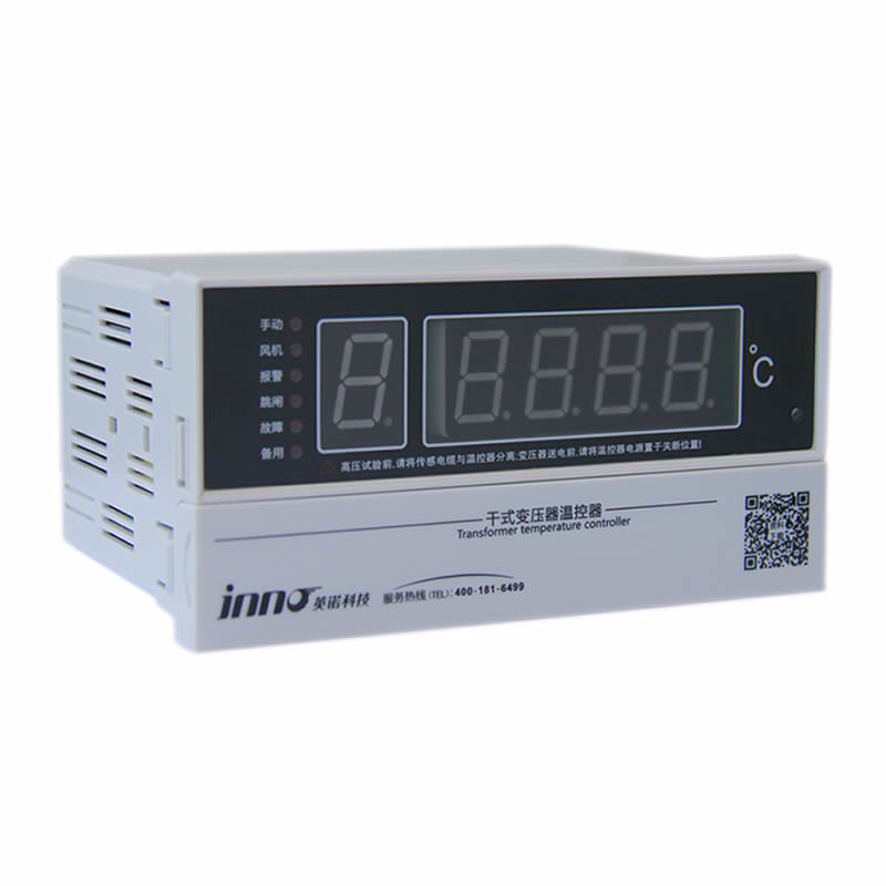
วิธี 3: ตัวบ่งชี้อุณหภูมิน้ำมันจำลองความร้อน (Winding Temperature Indicators)
ที่ ตัวบ่งชี้อุณหภูมิขดลวดจำลองความร้อน (WTI) - หรือที่เรียกว่า ก เครื่องจำลองอุณหภูมิจุดร้อน หรือ ตัวบ่งชี้ภาพความร้อน — เป็นเครื่องมือไฟฟ้าเครื่องกลแบบครบวงจรในตัวเอง ซึ่งประมาณอุณหภูมิจุดร้อนของขดลวดหม้อแปลงโดยใช้แบบจำลองความร้อนแบบอะนาล็อกของพฤติกรรมการเพิ่มขึ้นของความร้อนของหม้อแปลง. เป็นหนึ่งในอุปกรณ์ตรวจสอบอุณหภูมิหม้อแปลงที่มีการติดตั้งกันอย่างแพร่หลายมากที่สุดในการให้บริการทั่วโลก, พบได้ในหม้อแปลงไฟฟ้าจำหน่ายและกำลังจาก 1 MVA ถึงหลายร้อย MVA.
หลักการทำงาน
WTI ประกอบด้วย เทอร์โมมิเตอร์แบบหน้าปัด bimetallic ติดตั้งในช่องอุณหภูมิน้ำมัน PT100 บนถังหม้อแปลง, รวมกับสิ่งเล็กๆ องค์ประกอบความร้อน ได้รับพลังงานจากกระแสไฟฟ้าเป็นสัดส่วนกับกระแสโหลดของหม้อแปลง (จ่ายไฟผ่านหม้อแปลงกระแสเฉพาะ). องค์ประกอบตัวทำความร้อนเลียนแบบความร้อนที่เพิ่มขึ้นของI²R ของขดลวดที่อยู่เหนืออุณหภูมิน้ำมัน ดังนั้นตัวชี้เทอร์โมมิเตอร์จะอ่านอุณหภูมิที่แสดงถึงจุดร้อนของขดลวดโดยประมาณ แทนที่จะอ่านอุณหภูมิน้ำมันเพียงอย่างเดียว. โดยการปรับอัตราส่วนกระแสความร้อนและค่าคงที่เวลาความร้อนของชุดทำความร้อน, WTI สามารถปรับเทียบได้อย่างใกล้ชิดเพื่อให้ตรงกับพฤติกรรมความร้อนของขดลวดจริงที่กำหนดไว้ในรายงานการทดสอบการทำงานความร้อนจากโรงงานของหม้อแปลงไฟฟ้า.
Functional Features
- ให้ความต่อเนื่อง อุณหภูมิจุดร้อนที่คดเคี้ยวโดยประมาณ อ่านค่าบนหน้าปัดอะนาล็อกในพื้นที่ — ไม่ต้องใช้แหล่งจ่ายไฟภายนอกสำหรับการบ่งชี้พื้นฐาน
- บูรณาการ สัญญาณเตือนที่ปรับได้และหน้าสัมผัสการเดินทาง (โดยทั่วไปจะมีสองขั้นตอนการติดต่อที่เป็นอิสระ) สำหรับการเชื่อมต่อโดยตรงกับรีเลย์ป้องกันหรืออินพุตสัญญาณเตือน SCADA
- บิวท์อิน ตัวบ่งชี้มือลาก บันทึกอุณหภูมิสูงสุดนับตั้งแต่การรีเซ็ตด้วยตนเองครั้งล่าสุด ซึ่งมีประโยชน์สำหรับการวิเคราะห์หลังเหตุการณ์ของเหตุการณ์โอเวอร์โหลด
- ไม่จำเป็น 4–20mA หรือ PT100 เอาต์พุตแบบอะนาล็อก สำหรับการบูรณาการการตรวจสอบระยะไกล
- แยก หน้าสัมผัสควบคุมความเย็น สำหรับพัดลมอัตโนมัติหรือปั๊มสตาร์ท/หยุดตามอุณหภูมิฮอตสปอตโดยประมาณ
- มีจำหน่ายทั้ง ตัวบ่งชี้อุณหภูมิน้ำมัน (เสร็จแล้ว) การกำหนดค่า (วัดเฉพาะน้ำมันบนเท่านั้น, ไม่มีอินพุตกระแสโหลด) and full ตัวบ่งชี้อุณหภูมิที่คดเคี้ยว (WTI) การกำหนดค่าด้วยการชดเชยกระแสโหลด
การใช้งานและข้อจำกัด
ที่ การจำลองความร้อน WTI เป็นอุปกรณ์ป้องกันอุณหภูมิมาตรฐานของหม้อแปลงไฟฟ้าระบบจำหน่ายและหม้อแปลงส่งย่อยส่วนใหญ่ที่ให้บริการทั่วโลก เนื่องจากมีต้นทุนต่ำ, ความเรียบง่ายทางกล, และความเป็นอิสระจากแหล่งจ่ายไฟภายนอก. อย่างไรก็ตาม, แบบจำลองความร้อนแบบแอนะล็อกเป็นการนำเสนอพฤติกรรมความร้อนของขดลวดที่เกิดขึ้นจริงอย่างง่าย โดยไม่ได้คำนึงถึงการกระจายกระแสที่ไม่สม่ำเสมอ, รูปแบบการระบายความร้อนเฉพาะที่, หรือการเปลี่ยนแปลงคุณลักษณะทางความร้อนของขดลวดเนื่องจากการเสื่อมสภาพของฉนวน. สำหรับหม้อแปลงมูลค่าสูงที่สำคัญซึ่งความรู้ฮอตสปอตที่แม่นยำเป็นสิ่งจำเป็นสำหรับการจัดการชีวิตและการเพิ่มประสิทธิภาพโหลดแบบไดนามิก, การวัดอุณหภูมิขดลวดใยแก้วนำแสงโดยตรง ควรเสริมหรือแทนที่การจำลองความร้อนตาม WTI.
วิธี 4: Wireless Temperature Monitoring Sensors
เซ็นเซอร์อุณหภูมิหม้อแปลงไร้สาย ใช้โหนดตัวส่งสัญญาณที่ใช้พลังงานแบตเตอรี่เพื่อรวบรวมข้อมูลอุณหภูมิพื้นผิว ณ จุดการวัดที่กำหนด และถ่ายทอดการอ่านไปยังเกตเวย์กลางหรือแพลตฟอร์มการตรวจสอบระบบคลาวด์ผ่านทาง ZigBee, โลรา, 2.4กิกะเฮิรตซ์ RF, หรือ NB-IoT โปรโตคอล. สถาปัตยกรรมนี้ช่วยลดการเดินสายสัญญาณระหว่างเซ็นเซอร์และระบบตรวจสอบ ซึ่งเป็นข้อได้เปรียบที่สำคัญสำหรับการติดตั้งเพิ่มเติมและการติดตั้ง ซึ่งการใช้สายเครื่องมือวัดใหม่กับหม้อแปลงที่มีอยู่นั้นทำไม่ได้จริงหรือมีค่าใช้จ่ายสูง.
ข้อดีหลัก
- การติดตั้งโดยไม่ต้องใช้เครื่องมือบนพื้นผิวภายนอกของหม้อแปลง, ขั้วต่อบุชชิ่ง, การเชื่อมต่อบัสบาร์ LV, และตัวเชื่อมสายเคเบิล
- Supports เครือข่ายหลายจุด ครอบคลุมตำแหน่งการวัดหลายสิบตำแหน่งทั่วอ่าวหม้อแปลงหรือสถานีย่อยจากเกตเวย์เดียว
- ข้อมูลอุณหภูมิแบบเรียลไทม์พร้อมเกณฑ์การแจ้งเตือนที่กำหนดค่าได้และการแจ้งเตือนแบบพุชไปยังอุปกรณ์มือถือหรือระบบ SCADA
- Ideal for การตรวจสอบตู้หม้อแปลงชนิดแห้ง โดยที่อุณหภูมิพื้นผิวของขดลวดเป็นเป้าหมายการวัดหลัก
- การรวมระบบคลาวด์ช่วยให้สามารถติดตามและติดตามแนวโน้มจากการติดตั้งหม้อแปลงหลายตัวบนแพลตฟอร์มเดียวได้จากส่วนกลาง
ข้อจำกัด
เซ็นเซอร์ไร้สายวัด อุณหภูมิพื้นผิวหรือใกล้พื้นผิวเท่านั้น และไม่สามารถเข้าถึงจุดร้อนที่คดเคี้ยวภายในของหม้อแปลงจุ่มน้ำมันได้. โดยทั่วไปจำเป็นต้องเปลี่ยนแบตเตอรี่ทุกๆ 2-5 ปี ขึ้นอยู่กับการตั้งค่าช่วงเวลาการส่งข้อมูล. กรอบหุ้มหม้อแปลงโลหะจะลดทอนสัญญาณความถี่วิทยุ — การออกแบบการวางตำแหน่งเสาอากาศและการวางตำแหน่งรีพีทเตอร์จะต้องได้รับการแก้ไขระหว่างการทดสอบการทำงานของระบบ เพื่อให้มั่นใจในการส่งข้อมูลที่เชื่อถือได้.
วิธี 5: เทอร์โมกราฟฟีอินฟราเรด
Infrared thermal imaging cameras ตรวจจับรังสีแม่เหล็กไฟฟ้าที่ปล่อยออกมาจากพื้นผิวภายนอกของหม้อแปลงและแปลงเป็นแผนที่ความร้อนด้วยภาพที่ปรับเทียบแล้ว, ช่วยให้ช่างเทคนิคบำรุงรักษาสามารถระบุการไล่ระดับอุณหภูมิที่ผิดปกติทั่วบุชชิ่งได้, การเชื่อมต่อเทอร์มินัล, หม้อน้ำระบายความร้อน, และพื้นผิวถังในระหว่างการเยี่ยมชมการตรวจสอบตามกำหนดเวลาโดยไม่ต้องสัมผัสทางกายภาพกับอุปกรณ์ที่ใช้พลังงาน.
กล้องอินฟราเรดแบบมือถือเทียบกับ. แก้ไขเซ็นเซอร์ความร้อนออนไลน์
แบบพกพา กล้องถ่ายภาพความร้อนอินฟราเรด เป็นเครื่องมือมาตรฐานสำหรับการตรวจสอบหม้อแปลงตามรอบและให้ภาพความร้อนที่มีความละเอียดสูง เหมาะสำหรับรายงานการบำรุงรักษาและการเปรียบเทียบแนวโน้มในรอบการตรวจสอบที่ต่อเนื่องกัน. แก้ไขเซ็นเซอร์อินฟราเรดออนไลน์ ติดตั้งในหน้าต่างสังเกตเฉพาะบนเปลือกหม้อแปลงหรือแผงสวิตช์เกียร์ช่วยให้สามารถตรวจติดตามความร้อนอย่างต่อเนื่องของโซนภายนอกเฉพาะ - เชื่อมช่องว่างระหว่างช่วงเวลาการตรวจสอบตามกำหนดเวลาสำหรับสินทรัพย์ที่มีลำดับความสำคัญสูง.
ข้อดีและข้อจำกัดหลัก
การถ่ายภาพความร้อนแบบอินฟราเรดมีความเป็นเลิศในฐานะ ไม่ติดต่อ, เครื่องมือสำรวจอย่างรวดเร็ว สำหรับการตรวจจับข้อผิดพลาดภายนอกและเอกสารการบำรุงรักษา. สามารถใช้งานร่วมกับหม้อแปลงทุกประเภทและระดับแรงดันไฟฟ้าได้อย่างสมบูรณ์ และไม่จำเป็นต้องติดตั้งตัวหม้อแปลงแบบถาวร. อย่างไรก็ตาม, โดยพื้นฐานแล้วการวัดด้วยอินฟราเรดนั้นจำกัดอยู่ที่ การตรวจจับอุณหภูมิพื้นผิว — ไม่สามารถวัดอุณหภูมิจุดร้อนของขดลวดภายในถังหม้อแปลงได้, และจะให้เฉพาะภาพรวมเป็นระยะๆ แทนที่จะให้ความคุ้มครองแบบเรียลไทม์อย่างต่อเนื่องซึ่งจำเป็นสำหรับฟังก์ชันการเตือนและการป้องกันอัตโนมัติ.
การตรวจสอบอุณหภูมิหม้อแปลงไฟฟ้า: ตารางเปรียบเทียบเทคโนโลยี

| เกณฑ์ | ไฟเบอร์ออปติกเรืองแสง | PT100 Sensor | การจำลองความร้อน WTI | เซ็นเซอร์ไร้สาย | เทอร์โมกราฟฟีอินฟราเรด |
|---|---|---|---|---|---|
| ประเภทการวัด | จุดร้อนที่คดเคี้ยวโดยตรง | น้ำมัน / อุณหภูมิพื้นผิว | จุดร้อนโดยประมาณ (calculated) | อุณหภูมิพื้นผิว | อุณหภูมิพื้นผิว |
| โหมดการตรวจสอบ | ออนไลน์อย่างต่อเนื่อง | ออนไลน์อย่างต่อเนื่อง | ออนไลน์อย่างต่อเนื่อง | ออนไลน์อย่างต่อเนื่อง | เป็นระยะๆ / กำหนดไว้ |
| ภูมิคุ้มกันอีเอ็มไอ | ★★★★★ | ★★★ | ★★★★ | ★★★ | ★★★★ |
| ความแม่นยำในการวัด | ±0.5°ซ | ±0.3–1°ซ | ±2–5°ซ (โดยประมาณ) | ±1°ซ | ±2°ซ |
| การเข้าถึงที่คดเคี้ยวภายใน | ✅โดยตรง | ❌พื้นผิวเท่านั้น | ⚠️ประมาณการที่คำนวณแล้ว | ❌พื้นผิวเท่านั้น | ❌ภายนอกเท่านั้น |
| Real-Time Alarm | ✅ | ✅ | ✅ | ✅ | ❌ |
| ความซับซ้อนในการติดตั้ง | ปานกลาง (โรงงานหรือดัดแปลง) | เรียบง่าย | เรียบง่าย | น้อยที่สุด | ไม่มี (portable) |
| เหมาะสำหรับแช่น้ำมัน | ✅ | ✅ | ✅ | ⚠️ภายนอกเท่านั้น | ✅ |
| เหมาะสำหรับประเภทแห้ง | ✅ | ✅ | ⚠️มีจำนวนจำกัด | ✅ | ✅ |
| ไออีซี 60076-2 เป็นไปตามข้อกำหนด | ✅ | ⚠️ทางอ้อม | ⚠️ทางอ้อม | ❌ | ❌ |
| แอปพลิเคชั่นที่ดีที่สุด | หม้อแปลงไฟฟ้า HV ที่สำคัญ, การบริหารชีวิตที่คดเคี้ยว | อินพุตรีเลย์ป้องกันมาตรฐาน, การตรวจสอบน้ำมัน | หม้อแปลงไฟฟ้าระบบจำหน่าย, การป้องกันความร้อนตามปกติ | บุชชิ่ง, ขั้วต่อแอลวี, ชุดติดตั้งเพิ่มเติมแบบแห้ง | การตรวจสอบการบำรุงรักษา, การสำรวจข้อบกพร่องภายนอก |
7. การสร้างระบบตรวจสอบความร้อนของหม้อแปลงไฟฟ้าที่ดีที่สุด
มีประสิทธิภาพมากที่สุด transformer temperature monitoring solution ไม่ใช่อุปกรณ์ชิ้นเดียว แต่เป็นอุปกรณ์หลายชั้น, สถาปัตยกรรมบูรณาการที่รวมการตรวจจับโดยตรง, การได้มาของข้อมูล, การจัดการสัญญาณเตือน, และการบูรณาการระดับระบบเพื่อส่งมอบข่าวกรองความร้อนที่ดำเนินการได้ตลอดอายุการใช้งานของหม้อแปลง.
ชั้น 1 — Sensing: การจับคู่เทคโนโลยีกับจุดการวัด
การใช้งานการตรวจจับที่ครอบคลุมจะจัดการกับโซนความร้อนที่สำคัญทั้งหมดของหม้อแปลงพร้อมกัน. หัววัดไฟเบอร์ออปติกฟลูออเรสเซนต์ ถูกฝังอยู่ในชุดขดลวด HV และ LV ที่ตำแหน่งฮอตสปอตที่ระบุโดยโรงงานเพื่อให้ IEC โดยตรง 60076-2 การอ่านอุณหภูมิของขดลวดที่สอดคล้อง. เซ็นเซอร์ PT100 ถูกติดตั้งในช่องน้ำมันบนฝาถังสำหรับการวัดอุณหภูมิน้ำมันด้านบน และในท่อทางเข้า/ออกหม้อน้ำสำหรับการตรวจสอบระบบทำความเย็น. ก ตัวบ่งชี้อุณหภูมิขดลวดจำลองความร้อน (WTI) ติดตั้งอยู่บนแผงรวมหม้อแปลงเพื่อให้มีตัวบ่งชี้การสำรองข้อมูลระบบเครื่องกลไฟฟ้าในพื้นที่และหน้าสัมผัสสัญญาณเตือนอิสระสำหรับการป้องกันการสะดุดของรีเลย์. เครื่องส่งสัญญาณอุณหภูมิไร้สาย ใช้กับขั้วต่อขั้วต่อบุชชิ่ง, ข้อต่อบัสบาร์ LV, และการสิ้นสุดสายเคเบิลเพื่อขยายความครอบคลุมการตรวจสอบไปยังจุดเชื่อมต่อภายนอกที่มีความเสี่ยงสูงโดยไม่ต้องเดินสายเคเบิลเพิ่มเติม.
ชั้น 2 — การได้มาซึ่งข้อมูล
สัญญาณไฟเบอร์ออปติกได้รับการประมวลผลโดย เครื่องดีโมดูเลเตอร์เรืองแสงแบบหลายช่องสัญญาณ ที่แปลงการวัดเวลาการสลายตัวของแสงเป็นค่าอุณหภูมิที่สอบเทียบที่อัตราการสุ่มตัวอย่าง 1–10 วินาที. สัญญาณ PT100 จะถูกป้อนโดยตรงไปยังรีเลย์ป้องกันหม้อแปลง (เช่น, เอบีบี RET670, ซีเมนส์ 7UT) หรือเพื่ออุทิศตน โมดูลอินพุต RTD ในระบบควบคุมสถานีย่อย. ข้อมูลเซ็นเซอร์ไร้สายถูกรวบรวมโดย เกตเวย์ LoRa หรือ ZigBee ติดตั้งในห้องควบคุมสถานีย่อยหรือตู้ควบคุมสถานีย่อย.
ชั้น 3 — การสื่อสารและการบูรณาการ
กระแสข้อมูลอุณหภูมิทั้งหมดมาบรรจบกันที่ระบบอัตโนมัติของสถานีย่อยผ่าน ไออีซี 61850 GOOSE messaging สำหรับการส่งสัญญาณเตือนระดับการป้องกัน, Modbus TCP/RTU for SCADA integration, และ ดีเอ็นพี3 สำหรับการเชื่อมต่อระบบสาธารณูปโภค EMS. การใช้งานการปรับใช้ที่เชื่อมต่อกับคลาวด์ MQTT มากกว่า 4G/5G สำหรับการตรวจสอบระยะไกลและการแจ้งเตือนผ่านมือถือโดยไม่ต้องพึ่งพาโครงสร้างพื้นฐาน LAN ของสถานีย่อย.
ชั้น 4 — แพลตฟอร์มการตรวจสอบและการจัดการสัญญาณเตือน
ที่ แพลตฟอร์มซอฟต์แวร์ตรวจสอบความร้อนของหม้อแปลงไฟฟ้า มีแดชบอร์ดอุณหภูมิแบบเรียลไทม์สำหรับจุดตรวจจับทั้งหมด, การบันทึกแนวโน้มในอดีตพร้อมระยะเวลาการเก็บรักษาที่กำหนดได้, และโครงสร้างการจัดการสัญญาณเตือนสามชั้น. สัญญาณเตือนคำแนะนำ ที่อุณหภูมิ 95°C จุดที่คดเคี้ยวจะเริ่มต้นการยกระดับระบบทำความเย็นอัตโนมัติ. สัญญาณเตือนภัย ที่อุณหภูมิ 110°C จะกระตุ้นให้ผู้ปฏิบัติงานแจ้งเตือนและขั้นตอนการลดภาระ. สัญญาณเตือนที่สำคัญ ที่อุณหภูมิ 120°C (หรือเกณฑ์การเดินทางที่กำหนดของผู้ผลิตหม้อแปลงไฟฟ้า) เริ่มต้นการสะดุดรีเลย์ป้องกันอัตโนมัติเพื่อตัดการเชื่อมต่อหม้อแปลงจากการบริการก่อนที่ความร้อนจะเกิดขึ้น. ค่าเกณฑ์ทั้งหมดสามารถกำหนดค่าได้ และควรได้รับการตรวจสอบกับข้อมูลการออกแบบการระบายความร้อนของผู้ผลิตหม้อแปลงไฟฟ้าและคู่มือการโหลดที่เกี่ยวข้อง (ไออีซี 60076-7 or IEEE C57.91).
ชั้น 5 — การตอบสนองอัตโนมัติและการรวม SCADA
ในการเปิดใช้งานสัญญาณเตือน, ระบบดำเนินการลำดับการตอบสนองที่ประสานกัน: พัดลมและปั๊มระบบทำความเย็นจะเริ่มทำงานโดยอัตโนมัติเต็มประสิทธิภาพ; เอสเอ็มเอส, อีเมล, และส่งการแจ้งเตือนไปยังเจ้าหน้าที่ปฏิบัติการที่ได้รับมอบหมาย; คำสั่งการกำจัดโหลดจะถูกส่งไปยังรีเลย์ป้องกันต้นน้ำหากอุณหภูมิยังคงเพิ่มขึ้น; และที่เกณฑ์วิกฤต, คำสั่งการเดินทางอัตโนมัติจะถูกดำเนินการ. บูรณาการเต็มรูปแบบด้วย สกาด้า, อีเอ็มเอส, CMMS, และแพลตฟอร์มการจัดการสินทรัพย์ ช่วยให้มั่นใจได้ว่าเหตุการณ์ความร้อนทั้งหมดจะถูกบันทึกด้วยข้อมูลที่ประทับเวลา, ช่วยให้สามารถวิเคราะห์สาเหตุที่แท้จริงหลังเหตุการณ์และการรายงานการปฏิบัติตามกฎระเบียบ.
การกำหนดค่าระบบที่แนะนำตามประเภทหม้อแปลง
- หม้อแปลงส่งกำลังที่สำคัญ (≥100 MVA, 110กิโลโวลต์ขึ้นไป): เซ็นเซอร์ไขลานไฟเบอร์ออปติกฟลูออเรสเซนต์ (โรงงานฝังตัว, เอชวี + แอลวี) + น้ำมันพีที100 ตัวท็อป + ตัวบ่งชี้การสำรองข้อมูล WTI + เซ็นเซอร์เทอร์มินัลบุชชิ่งไร้สาย + SCADA เต็มรูปแบบ / ไออีซี 61850 บูรณาการ
- หม้อแปลงแช่น้ำมันอุตสาหกรรม (10–100 MVA): เซ็นเซอร์ไขลานไฟเบอร์ออปติกฟลูออเรสเซนต์ + การตรวจสอบน้ำมันและหม้อน้ำชั้นนำ PT100 + WTI พร้อมหน้าสัมผัสควบคุมความเย็น + การบูรณาการ Modbus SCADA
- หม้อแปลงไฟฟ้าแบบหล่อเรซินชนิดแห้ง: หัววัดไฟเบอร์ออปติกฟลูออเรสเซนต์ (ฝังอยู่ในขดลวดระหว่างการผลิต) + เซ็นเซอร์พื้นผิว PT100 + เซ็นเซอร์เทอร์มินัลบัสบาร์ LV ไร้สาย + จอแสดงผล HMI ท้องถิ่น
- การติดตั้งเพิ่มเติมหม้อแปลงไฟฟ้าระบบจำหน่าย: การเปลี่ยนหรืออัพเกรด WTI + เซ็นเซอร์พื้นผิวไร้สายบนขั้วต่อบุชชิ่ง + การแทรกโพรบไฟเบอร์ออปติกเสริมผ่านทางพอร์ตฝาครอบถัง + เกตเวย์การตรวจสอบระบบคลาวด์
- โปรแกรมตรวจสอบการบำรุงรักษา (ทุกประเภท): การสำรวจความร้อนอินฟราเรดเป็นระยะ (ขั้นต่ำปีละสองครั้ง) รวมกับการตรวจสอบข้อมูลการตรวจสอบออนไลน์สำหรับการตรวจสอบข้ามและเอกสารการปฏิบัติตามข้อกำหนด
8. กรณีศึกษาทั่วโลก: การตรวจสอบอุณหภูมิหม้อแปลงในการดำเนินการ

การปรับใช้ในโลกแห่งความเป็นจริงต่อไปนี้จะอธิบายวิธีการ transformer thermal monitoring systems ได้ส่งมอบการป้องกันที่วัดผลได้และมูลค่าการดำเนินงานในหลากหลายอุตสาหกรรม, ระดับแรงดันไฟฟ้า, และภูมิภาคทางภูมิศาสตร์.
กรณีศึกษา 1 — สถานีส่งกำลังย่อย, สหราชอาณาจักร
ผู้ให้บริการเครือข่ายการส่งสัญญาณรายใหญ่ของสหราชอาณาจักรได้รับการติดตั้งเพิ่มเติม เซ็นเซอร์อุณหภูมิขดลวดใยแก้วนำแสงเรืองแสง ให้เป็นตัวแปลงอัตโนมัติขนาด 400kV สิบสองตัวที่สถานีย่อยเชื่อมต่อโครงข่ายกริดที่สำคัญ. Prior to installation, ผู้ประกอบการพึ่งพิงแต่เพียงผู้เดียว ตัวบ่งชี้ WTI การจำลองความร้อน และการวัดน้ำมัน PT100 ระดับชั้นนำ — ทั้งสองการวัดไม่ได้ให้ความรู้โดยตรงเกี่ยวกับสภาวะฮอตสปอตของขดลวดที่เกิดขึ้นจริงภายใต้วงจรโหลดแบบไดนามิก. ภายในฤดูกาลปฏิบัติการแรกหลังจากการทดสอบการใช้งานเซ็นเซอร์ไฟเบอร์ออปติก, ระบบตรวจสอบระบุหน่วยสองหน่วยที่ทำงานด้วยอุณหภูมิจุดร้อนที่คดเคี้ยว 18–23°C สูงกว่าค่าที่ระบุของ WTI ภายใต้เงื่อนไขความต้องการสูงสุด - ความคลาดเคลื่อนที่มีสาเหตุมาจากพารามิเตอร์แบบจำลองความร้อนที่เบี่ยงเบนไปในหน่วยอายุ. เกณฑ์วิธีการจัดการโหลดถูกปรับตามนั้น, และหม้อแปลงทั้งสองตัวถูกกำหนดให้มีการตรวจสอบตามแผน แทนที่จะเผชิญกับความเสี่ยงที่จะเกิดความล้มเหลวเนื่องจากความร้อนโดยไม่ได้วางแผนไว้ในช่วงที่มีความต้องการใช้งานสูงสุดในฤดูหนาว. ผู้ปฏิบัติงานประเมินว่าการแทรกแซงดังกล่าวช่วยป้องกันไม่ให้ต้นทุนไฟฟ้าดับเกินกว่า 2 ล้านปอนด์ต่อหน่วยที่ได้รับผลกระทบ.
กรณีศึกษา 2 — วิทยาเขตศูนย์ข้อมูล, สิงคโปร์
ผู้ดำเนินการศูนย์ข้อมูลระดับไฮเปอร์สเกลที่จัดการแปดคน หม้อแปลงไฟฟ้าแบบหล่อเรซินชนิดแห้ง ที่สถานที่ระดับ IV ได้ปรับใช้สถาปัตยกรรมการตรวจสอบแบบไฮบริดผสมผสานกัน หัววัดไฟเบอร์ออปติกฟลูออเรสเซนต์แบบฝังจากโรงงาน ในขดลวด HV และ LV ของหม้อแปลงแต่ละตัวด้วย เครือข่ายเซ็นเซอร์อุณหภูมิไร้สาย ครอบคลุมการเชื่อมต่อบัสบาร์ LV, cable termination lugs, และขั้วขาเข้าของแผงจำหน่ายหลัก. ทั้งหมด 96 จุดตรวจวัดทั่วทั้งหม้อแปลงทั้งแปดตัวจะป้อนเข้าสู่แพลตฟอร์มการตรวจสอบคลาวด์แบบรวมศูนย์พร้อมการแจ้งเตือนแบบพุชบนมือถือที่กำหนดค่าไว้สำหรับสิ่งอำนวยความสะดวก 24/7 ทีมปฏิบัติการ. ในระหว่างการทดสอบโอเวอร์โหลดการขยายกำลังการผลิตสิบแปดเดือนหลังจากการทดสอบเดินเครื่อง, ระบบไฟเบอร์ออปติกตรวจพบอุณหภูมิฮอตสปอตของขดลวดที่ 158°C ในหม้อแปลงตัวเดียว — 23°C เหนือตัวบ่งชี้พื้นผิว WTI — กระตุ้นให้เกิดการถ่ายโอนโหลดทันทีไปยังยูนิตสแตนด์บาย. การวิเคราะห์ทางความร้อนหลังเหตุการณ์ยืนยันว่าฉนวนเรซินของหม้อแปลงที่ได้รับผลกระทบได้เริ่มต้นการแตกร้าวระดับไมโครที่พื้นผิว ซึ่งสอดคล้องกับการสัมผัสอุณหภูมิที่สูงเกินไปอย่างต่อเนื่อง, ตรวจสอบการแทรกแซงของระบบตั้งแต่เนิ่นๆ.
กรณีศึกษา 3 – สถานีไฟฟ้าย่อยรางรถไฟ, จีน
ผู้ดำเนินการรถไฟในเมืองได้ติดตั้งสถานีไฟฟ้าย่อยแบบฉุดข้าม 24 สถานีด้วย ระบบเทอร์โมมิเตอร์ไฟเบอร์ออปติกฟลูออเรสเซนต์แบบหลายช่องสัญญาณ การตรวจสอบจุดร้อนที่คดเคี้ยวในหม้อแปลงไฟฟ้าแบบฉุดเชื่อมต่อแบบสก็อต. ภาวะชั่วครู่ในการสลับความถี่สูงและสนามแม่เหล็กไฟฟ้าแรงสูงที่สร้างโดยระบบอินเวอร์เตอร์แบบฉุดลาก ทำให้การตรวจสอบการพันของขดลวดที่ใช้ PT100 แบบเดิมๆ หมดไป — เซ็นเซอร์อิเล็กทรอนิกส์ในสภาพแวดล้อมนี้ประสบปัญหาสัญญาณรบกวนจากการวัดอย่างต่อเนื่องและการเตือนที่ผิดพลาด. สถาปัตยกรรมการตรวจจับไฟเบอร์ออปติกทั้งหมดขจัดการแจ้งเตือนที่ผิดพลาดที่เกี่ยวข้องกับ EMI โดยสิ้นเชิง ในขณะที่ให้ความแม่นยำของฮอตสปอตที่คดเคี้ยว ±0.5°C ทั่วทั้งเครือข่าย. ระบบเชื่อมต่อโดยตรงกับทางรถไฟ ระบบการจัดการพลังงาน SCADA via IEC 61850, ช่วยให้สามารถควบคุมการระบายความร้อนแบบอัตโนมัติและเพิ่มประสิทธิภาพการกระจายโหลดโดยอิงตามพื้นที่ระบายความร้อนแบบเรียลไทม์ในหม้อแปลงไฟฟ้าแบบฉุดแต่ละตัว.
กรณีศึกษา 4 – โรงกลั่นปิโตรเคมี, ซาอุดีอาระเบีย
ผู้ดำเนินการโรงกลั่นรายใหญ่ที่จัดการสิบสี่ 11หม้อแปลงหน่วยแช่น้ำมัน kV ในเขตพื้นที่อันตรายจำแนกได้ดำเนินการผสมผสานการอัพเกรดการติดตามที่ครอบคลุม เซ็นเซอร์น้ำมันชั้นนำ PT100 พิกัด ATEX, ตัวบ่งชี้ WTI การจำลองความร้อน พร้อมเอาต์พุตระยะไกล 4–20mA, และ เครื่องส่งสัญญาณอุณหภูมิไร้สายที่ปลอดภัยอย่างแท้จริง บนขั้วต่อบุชชิ่งหม้อแปลงและกล่องปลายสาย HV. เครือข่ายไร้สายขจัดความจำเป็นในการใช้สายเคเบิลอุปกรณ์ใหม่ที่ทำงานผ่านถาดสายเคเบิลที่แออัดในพื้นที่จัดประเภท — ข้อได้เปรียบด้านความปลอดภัยและต้นทุนที่สำคัญ. แพลตฟอร์มการตรวจสอบแบบรวมแจ้งว่าอุณหภูมิขั้วต่อบุชชิ่งผิดปกติเพิ่มขึ้น 41°C เหนือสภาพแวดล้อมบนหม้อแปลงตัวเดียวภายในหกสัปดาห์หลังการทดสอบเดินเครื่อง, นำไปสู่การค้นพบแคลมป์ขั้วต่อที่มีแรงบิดต่ำกว่าอย่างรุนแรงซึ่งพลาดไประหว่างการหยุดซ่อมบำรุงตามกำหนดครั้งก่อน.
กรณีศึกษา 5 — สถานีไฟฟ้าย่อยกังหันลม, เยอรมนี
ผู้พัฒนาพลังงานทดแทนมอบหมายให้ก 250 หม้อแปลงไฟฟ้าเก็บพลังงานลมนอกชายฝั่ง MVA พร้อมอุปกรณ์ หัววัดไฟเบอร์ออปติกฟลูออเรสเซนต์แบบฝังจากโรงงาน ทั้งในขดลวด HV และ LV, รวมกับ เซ็นเซอร์น้ำมันตัวท็อป PT100, การตรวจสอบอุณหภูมิส่วนต่างของหม้อน้ำ, และก WTI indicator ให้การป้องกันการสำรองข้อมูลภายในเครื่องที่เป็นอิสระ. ระบบไฟเบอร์ออปติกจะป้อนข้อมูลฮอตสปอตแบบเรียลไทม์ไปยังแพลตฟอร์ม SCADA ของฟาร์มกังหันลม, เปิดใช้งานการเพิ่มประสิทธิภาพการโหลดหม้อแปลงแบบไดนามิก - ช่วยให้ผู้ปฏิบัติงานสามารถดันเอาต์พุตของหม้อแปลงให้สูงกว่าระดับแผ่นป้ายได้อย่างปลอดภัยในช่วงเวลาที่มีอุณหภูมิแวดล้อมและทรัพยากรลมที่เหมาะสม, ในขณะเดียวกันก็ลดการสร้างโดยอัตโนมัติเมื่ออุณหภูมิฮอตสปอตเข้าใกล้ IEC 60076-7 เกณฑ์การโหลดฉุกเฉิน. ความสามารถในการโหลดแบบไดนามิกช่วยเพิ่มผลผลิตพลังงานต่อปีโดยประมาณ 3.2% เมื่อเปรียบเทียบกับการดำเนินการจำกัดป้ายชื่อคงที่แบบอนุรักษ์นิยม.
คำถามที่พบบ่อย: การตรวจสอบอุณหภูมิหม้อแปลงไฟฟ้า
1. เหตุใดการตรวจสอบอุณหภูมิหม้อแปลงจึงมีความสำคัญ?
ฉนวนหม้อแปลง — ส่วนใหญ่เป็นกระดาษเซลลูโลสในหน่วยเติมน้ำมันและเรซินหล่อในหน่วยชนิดแห้ง — ย่อยสลายอย่างถาวรเมื่อสัมผัสกับความร้อน. ตามแบบจำลองอายุเนื่องจากความร้อนของ Arrhenius ที่เข้ารหัสใน IEC 60076-7, ทุกๆ 6–10°C ของอุณหภูมิที่สูงเกินไปอย่างต่อเนื่องจะลดอายุการใช้งานของฉนวนที่เหลืออยู่ครึ่งหนึ่ง. ปราศจาก การตรวจสอบอุณหภูมิหม้อแปลงอย่างต่อเนื่อง, การย่อยสลายจากความร้อนดำเนินไปอย่างมองไม่เห็นจนกระทั่งความล้มเหลวของฉนวนทำให้เกิดไฟฟ้าดับโดยไม่ได้วางแผนไว้, ไฟ, หรือการสูญเสียหม้อแปลงไฟฟ้าอย่างรุนแรง. การตรวจสอบเชิงรุกช่วยให้สามารถบำรุงรักษาตามเงื่อนไขได้, การจัดการโหลดแบบไดนามิก, และการแทรกแซงอย่างทันท่วงทีก่อนที่ความเสียหายจากความร้อนจะไม่สามารถกลับคืนสภาพเดิมได้.
2. อะไรคือความแตกต่างระหว่างตัวบ่งชี้อุณหภูมิที่คดเคี้ยว (WTI) และเซ็นเซอร์ไขลานไฟเบอร์ออปติกโดยตรง?
ก ตัวบ่งชี้อุณหภูมิขดลวดจำลองความร้อน (WTI) ประมาณการอุณหภูมิจุดร้อนที่คดเคี้ยวโดยใช้แบบจำลองความร้อนแบบอะนาล็อก โดยจะวัดอุณหภูมิน้ำมันสูงสุด และเพิ่มอุณหภูมิที่เพิ่มขึ้นตามสัดส่วนของกระแสโหลด. การประมาณการนี้มีความไม่แน่นอนโดยธรรมชาติอยู่ที่ ±2–5°C หรือมากกว่า, โดยเฉพาะอย่างยิ่งภายใต้สภาวะโหลดไดนามิกหรือเมื่อคุณลักษณะทางความร้อนของหม้อแปลงเปลี่ยนแปลงเนื่องจากการเสื่อมสภาพ. ก เซ็นเซอร์ขดลวดใยแก้วนำแสงเรืองแสง วัดอุณหภูมิจริงที่ตำแหน่งฮอตสปอตทางกายภาพภายในขดลวด โดยให้ค่าโดยตรง, การอ่านแบบเรียลไทม์ด้วยความแม่นยำ ±0.5°C ที่ไม่ต้องใช้สมมติฐานเกี่ยวกับแบบจำลองความร้อน. สำหรับหม้อแปลงมูลค่าสูงที่สำคัญ, การวัดใยแก้วนำแสงโดยตรงให้ความมั่นใจในการประเมินสภาพความร้อนสูงกว่าการจำลอง WTI เพียงอย่างเดียวอย่างมีนัยสำคัญ.
3. อุณหภูมิใดที่ควรกระตุ้นให้เกิดสัญญาณเตือนการพันของหม้อแปลง?
เกณฑ์การเตือนขึ้นอยู่กับระดับฉนวนของหม้อแปลง, คะแนนการออกแบบ, และมาตรฐานการโหลดที่ใช้บังคับ. สำหรับหม้อแปลงน้ำมันแร่มาตรฐานที่มีฉนวนเซลลูโลสคลาส A, ไออีซี 60076-7 กำหนด ขีดจำกัดฮอตสปอตต่อเนื่องที่ 98°C สำหรับการโหลดแบบวนปกติ, กับ โหลดฉุกเฉินจำกัดได้ถึง 140°C สำหรับปฏิบัติการฉุกเฉินระยะสั้น. การตั้งค่ารีเลย์ป้องกันโดยทั่วไปใช้ สัญญาณเตือนขั้นแรกที่อุณหภูมิ 100–110°C ฮอตสปอตที่คดเคี้ยวเพื่อเริ่มการยกระดับการทำความเย็นและการแจ้งเตือนผู้ปฏิบัติงาน, ด้วย ทริปขั้นที่สองที่อุณหภูมิ 120–130°C เพื่อตัดการเชื่อมต่อหม้อแปลงโดยอัตโนมัติ. สำหรับหม้อแปลงคาสเรซินชนิดแห้ง, คลาสความร้อน F (155องศาเซลเซียส) และคลาส H (180องศาเซลเซียส) ขดลวดมีอุณหภูมิการทำงานที่อนุญาตสูงกว่า — ศึกษาเอกสารประกอบของผู้ผลิตหม้อแปลงไฟฟ้าสำหรับการตั้งค่าเฉพาะรุ่น.
4. สามารถติดตั้งหัววัดไฟเบอร์ออปติกฟลูออเรสเซนต์เข้ากับหม้อแปลงจุ่มน้ำมันที่มีอยู่ได้หรือไม่?
ใช่, ในหลายกรณี. ชุดติดตั้งเพิ่มเซนเซอร์ไฟเบอร์ออปติกฟลูออเรสเซนต์ ในหม้อแปลงไฟฟ้าแบบจุ่มน้ำมันที่มีอยู่นั้นเป็นไปได้ทางเทคนิคในระหว่างการหยุดซ่อมบำรุงตามแผน เมื่อหม้อแปลงถูกตัดพลังงานและระบายน้ำมันหรือลดลงบางส่วน. โพรบจะถูกสอดผ่านฝาครอบถังหม้อแปลงผ่านข้อต่อไฟเบอร์ฟีดทรูเฉพาะ และนำเข้าไปในชุดขดลวดโดยใช้เครื่องมือสอดที่ยืดหยุ่น. ความเป็นไปได้เฉพาะขึ้นอยู่กับการก่อสร้างที่คดเคี้ยว, จุดเข้าถึงถังที่มีอยู่, และคำแนะนำของผู้ผลิตหม้อแปลงไฟฟ้า. สำหรับการจัดซื้อหม้อแปลงไฟฟ้าใหม่, การระบุหัววัดไฟเบอร์ออปติกที่ติดตั้งจากโรงงานในระหว่างการผลิตเป็นแนวทางที่ต้องการ เนื่องจากช่วยให้มั่นใจได้ว่าเซนเซอร์จะวางตำแหน่งที่เหมาะสมที่สุดที่ตำแหน่งฮอตสปอตที่ออกแบบ.
5. อะไรคือความแตกต่างระหว่างอุณหภูมิน้ำมันสูงสุดและอุณหภูมิจุดร้อนที่คดเคี้ยว?
อุณหภูมิน้ำมันสูงสุด คืออุณหภูมิของน้ำมันฉนวนที่จุดสูงสุดในถังหม้อแปลง — วัดโดย a เซ็นเซอร์ PT100 ในช่องฝาถังน้ำมัน. มันแสดงถึงสถานะความร้อนจำนวนมากของตัวกลางทำความเย็นของหม้อแปลง. อุณหภูมิจุดร้อนที่คดเคี้ยว เป็นจุดอุณหภูมิสูงสุดภายในตัวนำขดลวดและชุดฉนวน - โดยทั่วไปจะอยู่ที่ส่วนบนของขดลวดและสูงกว่าอุณหภูมิน้ำมันโดยรอบอย่างสม่ำเสมอ 15–40°C ขึ้นอยู่กับระดับโหลดและโหมดการทำความเย็น. มันคืออุณหภูมิจุดร้อนที่คดเคี้ยว, ไม่ใช่อุณหภูมิน้ำมันสูงสุด, ที่ควบคุมอัตราการเสื่อมสภาพของฉนวนโดยตรงและความสามารถในการรับน้ำหนักที่อนุญาต. การใช้อุณหภูมิน้ำมันสูงสุดเพียงอย่างเดียวจะประเมินความเครียดจากความร้อนบนฉนวนหม้อแปลงต่ำอย่างเป็นระบบ.
6. ระบบตรวจสอบอุณหภูมิหม้อแปลงต้องเป็นไปตามมาตรฐาน IEC หรือไม่?
ใช่. มาตรฐานหลักที่ใช้บังคับสำหรับ การตรวจสอบอุณหภูมิหม้อแปลง เป็น ไออีซี 60076-2 (อุณหภูมิที่เพิ่มขึ้นสำหรับหม้อแปลงที่แช่ของเหลว — กำหนดวิธีการวัดฮอตสปอต), ไออีซี 60076-7 (คู่มือการโหลดสำหรับหม้อแปลงไฟฟ้ากำลังแบบจุ่มน้ำมัน — กำหนดแบบจำลองอายุความร้อนและขีดจำกัดการโหลด), และ ไออีซี 60354 (คู่มือการโหลดหม้อแปลงไฟฟ้ากำลังแบบจุ่มน้ำมัน, แทนที่โดย IEC 60076-7 แต่ยังคงอ้างอิงอยู่). สำหรับหม้อแปลงชนิดแห้ง, ไออีซี 60076-11 ใช้. การรวมรีเลย์ป้องกันและระบบตรวจสอบมีดังนี้ ไออีซี 61850 สำหรับการสื่อสารอัตโนมัติของสถานีย่อย. ผู้ซื้อควรยืนยันว่าระบบการตรวจสอบที่นำเสนอนั้นได้รับการออกแบบตามมาตรฐานเหล่านี้ และความถูกต้องของเซ็นเซอร์และความสามารถในการตรวจสอบย้อนกลับของการสอบเทียบได้รับการจัดทำเป็นเอกสารไว้ตามนั้น.
7. การตรวจวัดอุณหภูมิแบบไร้สายเหมาะสำหรับใช้ภายในถังหม้อแปลงแช่น้ำมันหรือไม่?
เลขที่. เซ็นเซอร์วัดอุณหภูมิแบบไร้สาย เป็นอุปกรณ์อิเล็กทรอนิกส์ที่ต้องใช้แหล่งพลังงานแบตเตอรี่และการส่งสัญญาณความถี่วิทยุ ซึ่งทั้งสองอย่างนี้เข้ากันไม่ได้กับภายในถังหม้อแปลงไฟฟ้าที่เติมน้ำมัน. เซ็นเซอร์ไร้สายเหมาะสำหรับการใช้งานตรวจสอบพื้นผิวหม้อแปลงภายนอก: การเชื่อมต่อขั้วต่อบุชชิ่ง, ข้อต่อบัสบาร์ LV, กล่องปลายสาย, และพื้นผิวตู้หม้อแปลงชนิดแห้ง. สำหรับการตรวจสอบจุดร้อนของขดลวดภายในของหม้อแปลงจุ่มน้ำมัน, เซนเซอร์ไฟเบอร์ออปติกเรืองแสง เป็นเทคโนโลยีเดียวที่สามารถติดตั้งได้อย่างปลอดภัยภายในถังหม้อแปลงไฟฟ้า.
8. เซ็นเซอร์วัดอุณหภูมิไฟเบอร์ออปติกฟลูออเรสเซนต์มีอายุการใช้งานนานเท่าใดในการให้บริการหม้อแปลงไฟฟ้า?
หัววัดตรวจจับไฟเบอร์ออปติกฟลูออเรสเซนต์ เป็นส่วนประกอบทางแสงแบบพาสซีฟที่ไม่มีองค์ประกอบทางไฟฟ้าที่ทำงานอยู่, moving parts, หรือวัสดุสิ้นเปลืองที่จุดตรวจจับ. ภายใต้สภาวะการทำงานของหม้อแปลงปกติ — รวมถึงการแช่น้ำมันแร่อย่างต่อเนื่อง, การหมุนเวียนความร้อนระหว่างอุณหภูมิโดยรอบและอุณหภูมิฮอตสปอตที่กำหนด, และการสัมผัสกับก๊าซละลายและความชื้น — อายุการใช้งานภาคสนามที่บันทึกไว้มีอายุการใช้งานเกิน 20–25 ปี โดยไม่ลดความแม่นยำในการวัดหรือความสมบูรณ์ของเซ็นเซอร์. อุปกรณ์อิเล็กทรอนิกส์ดีโมดูเลเตอร์ภายนอกมีอายุการออกแบบโดยทั่วไปอยู่ที่ 10-15 ปี โดยมีการบำรุงรักษาตามปกติ. อายุการใช้งานที่ยาวนานนี้ทำให้การตรวจจับด้วยไฟเบอร์ออปติกเป็นการลงทุนที่คุ้มค่าตลอดอายุการใช้งานของสินทรัพย์หม้อแปลง.
9. ระบบตรวจสอบอุณหภูมิหม้อแปลงสามารถทำงานร่วมกับแพลตฟอร์ม SCADA หรือ EMS ที่มีอยู่ได้หรือไม่?
ใช่. ที่สำคัญทั้งหมด transformer thermal monitoring systems รองรับโปรโตคอลการสื่อสารอุตสาหกรรมมาตรฐานที่จำเป็นสำหรับ SCADA, อีเอ็มเอส, และการรวมระบบอัตโนมัติของสถานีย่อย. โปรโตคอลที่รองรับทั่วไป ได้แก่ ไออีซี 61850 (ห่านและ MMS) สำหรับการสื่อสารสถานีย่อยระดับการป้องกัน, Modbus RTU/TCP สำหรับการเชื่อมต่อ SCADA ทั่วไป, ดีเอ็นพี3 สำหรับระบบสาธารณูปโภค EMS และระบบควบคุมระยะไกล, และ MQTT มากกว่า 4G/5G สำหรับการปรับใช้การตรวจสอบระยะไกลบนคลาวด์. บูรณาการกับ ระบบการจัดการบำรุงรักษาด้วยคอมพิวเตอร์ (CMMS) และ แพลตฟอร์มการจัดการสินทรัพย์ดิจิทัล ช่วยให้สามารถสร้างคำสั่งงานอัตโนมัติในเหตุการณ์การแจ้งเตือนและแนวโน้มอย่างต่อเนื่องของตัวบ่งชี้สภาพความร้อนของหม้อแปลง ควบคู่ไปกับสตรีมข้อมูลการตรวจสอบสภาพอื่นๆ.
10. ฉันจะเลือกโซลูชันการตรวจสอบอุณหภูมิหม้อแปลงที่ดีที่สุดสำหรับการใช้งานเฉพาะของฉันได้อย่างไร?
ทางออกที่ดีที่สุดขึ้นอยู่กับปัจจัยหลักสี่ประการ. อันดับแรก, ประเภทหม้อแปลงและระดับแรงดันไฟฟ้า: หน่วยแช่น้ำมันที่สูงกว่า 10kV ได้รับประโยชน์สูงสุดจากการตรวจสอบขดลวดใยแก้วนำแสงโดยตรง; ยูนิตแบบแห้งได้รับการบริการอย่างดีจากโพรบไฟเบอร์ออปติกแบบฝังรวมกับเซ็นเซอร์พื้นผิวไร้สาย. ที่สอง, ค่าวิกฤตและค่าทดแทน: หม้อแปลงส่งกำลังด้านบน 100 MVA ที่มีระยะเวลารอคอยการเปลี่ยนทดแทน 12–24 เดือนทำให้การตรวจสอบไฟเบอร์ออปติกมีความครอบคลุม; หม้อแปลงไฟฟ้าระบบจำหน่ายอาจได้รับการปกป้องอย่างเพียงพอโดย WTI บวก PT100 พร้อมการตรวจสอบอินฟราเรดเป็นระยะ. ที่สาม, สร้างใหม่เทียบกับ. ชุดติดตั้งเพิ่มเติม: หัววัดไฟเบอร์ออปติกแบบฝังจากโรงงานเป็นแนวทางที่คุ้มค่าที่สุดสำหรับหม้อแปลงใหม่; โครงการติดตั้งเพิ่มเติมควรประเมินความเป็นไปได้ของการแทรกโพรบเทียบกับการตรวจสอบภายนอกแบบไร้สายเป็นเส้นทางการอัพเกรดหลัก. ที่สี่, ข้อกำหนดในการบูรณาการ: สิ่งอำนวยความสะดวกที่มี SCADA หรือ IEC ที่มีอยู่ 61850 โครงสร้างพื้นฐานอัตโนมัติของสถานีย่อยควรระบุระบบการตรวจสอบด้วยการสนับสนุนโปรโตคอลดั้งเดิมเพื่อหลีกเลี่ยงการรวมมิดเดิลแวร์ที่มีค่าใช้จ่ายสูง. ติดต่อซัพพลายเออร์ที่เชี่ยวชาญด้านการตรวจสอบหม้อแปลงเพื่อขอคำแนะนำระบบเฉพาะสถานที่โดยพิจารณาจากข้อมูลป้ายชื่อหม้อแปลงของคุณ, กำลังโหลดโปรไฟล์, และวัตถุประสงค์การติดตาม.
รับโซลูชันการตรวจสอบอุณหภูมิหม้อแปลงที่เหมาะสมสำหรับโครงการของคุณ
ไม่ว่าคุณจะทดสอบการใช้งานหม้อแปลงไฟฟ้าแรงสูงตัวใหม่, การอัพเกรดการป้องกันสินทรัพย์ที่สำคัญที่มีอายุมากขึ้น, หรือสร้างโปรแกรมตรวจสอบความร้อนทั่วทั้งกลุ่มยานพาหนะในสถานีย่อยหลายแห่ง, การเลือกส่วนผสมที่เหมาะสมของ เซนเซอร์ไฟเบอร์ออปติกเรืองแสง, เครื่องตรวจจับ PT100, ตัวบ่งชี้การจำลองความร้อน, และเทคโนโลยีการตรวจสอบแบบไร้สาย เป็นการตัดสินใจที่ส่งผลโดยตรงต่ออายุการใช้งานของหม้อแปลง, ความน่าเชื่อถือในการดำเนินงาน, และความปลอดภัยของบุคลากร.
ฟจินโน (ฝูโจวนวัตกรรมวิทยาศาสตร์อิเล็กทรอนิกส์&บริษัท เทค จำกัด, บจ.) เชี่ยวชาญใน ระบบตรวจสอบอุณหภูมิหม้อแปลงใยแก้วนำแสงเรืองแสง ด้วยประสบการณ์การใช้งานสวิตช์เกียร์ไฟฟ้าแรงสูงมานานกว่าทศวรรษ, หม้อแปลงไฟฟ้า, อุปกรณ์จีไอเอส, หม้อแปลงชนิดแห้ง, และระบบส่งกำลังฉุดราง. Our engineering team provides application-specific system design, factory calibration, รองรับการติดตั้ง, และการบริการทางเทคนิคระยะยาวสำหรับโครงการทุกขนาด ตั้งแต่การอัพเกรดการป้องกันหม้อแปลงเดี่ยวไปจนถึงโปรแกรมการตรวจสอบยูทิลิตี้หลายไซต์.
- 📧 อีเมล: เว็บ@fjinno.net
- 📱 วอทส์แอพพ์ / วีแชท / โทรศัพท์: +86 135 9907 0393
- 😢 คิวคิว: 3408968340
- 🌐 เว็บไซต์: www.fjinno.net
- 📍 ที่อยู่: สวนอุตสาหกรรมเครือข่าย Liandong U Grain, No.12 ถนนซิงเย่ตะวันตก, ฝูโจว, ฝูเจี้ยน, จีน
ข้อสงวนสิทธิ์: ข้อมูลทางเทคนิค, เกณฑ์อุณหภูมิ, และการอ้างอิงมาตรฐานในบทความนี้มีไว้เพื่อวัตถุประสงค์ในการแนะนำทั่วไปเท่านั้น. การตั้งค่าการป้องกันหม้อแปลงเฉพาะ, ข้อมูลจำเพาะของเซ็นเซอร์, และการกำหนดค่าระบบจะต้องกำหนดโดยวิศวกรไฟฟ้าที่มีคุณสมบัติตามเอกสารของผู้ผลิตหม้อแปลงไฟฟ้า, มาตรฐาน IEC และ IEEE ที่บังคับใช้, and local regulatory requirements. ปฏิบัติตามขั้นตอนความปลอดภัยที่กำหนดไว้เสมอเมื่อทำงานกับหรือใกล้กับอุปกรณ์ไฟฟ้าที่มีพลังงานไฟฟ้า.

เซ็นเซอร์อุณหภูมิไฟเบอร์ออปติก, ระบบตรวจสอบอัจฉริยะ, จำหน่ายผู้ผลิตใยแก้วนำแสงในประเทศจีน
 |
 |
 |