 Волоконно-оптические датчики температуры INNO ,Системы контроля температуры.
- Transformer overheating is responsible for the majority of premature insulation failures and unplanned outages in power networks worldwide — making temperature monitoring one of the highest-value investments in asset protection.
- The five primary transformer temperature monitoring technologies are: флуоресцентная волоконно-оптическая термометрия, Резистивные датчики температуры PT100, thermal simulation oil temperature indicators, беспроводные датчики температуры, и инфракрасная термография.
- Флуоресцентные оптоволоконные датчики are the only technology capable of direct winding hot-spot measurement inside energized transformers with full EMI immunity and ±0.5°C accuracy — making them the gold standard for critical high-voltage assets.
- Датчики PT100 are the industry-standard contact thermometer for top oil temperature and cooling system monitoring, widely integrated into transformer protection relays and SCADA systems.
- Thermal simulation oil temperature indicators calculate estimated winding hot-spot temperature using an analog thermal model of the transformer’s heat rise characteristics — a cost-effective solution for routine protection on distribution transformers.
- Беспроводные датчики температуры provide cable-free multi-point monitoring on transformer surfaces, втулки, and cable terminations — ideal for retrofit installations and dry-type transformer enclosures.
- Инфракрасная термография delivers non-contact visual heat mapping for scheduled maintenance inspections but cannot provide the continuous real-time alarming that online monitoring systems offer.
- The best transformer temperature monitoring solution combines direct winding hot-spot sensing with top oil temperature measurement, multi-tier alarm management, and integration with existing SCADA or EMS platforms.
1. What Is a Power Transformer? The Backbone of Every Electrical Grid

A силовой трансформатор is a static electromagnetic device that transfers electrical energy between two or more circuits through electromagnetic induction, simultaneously stepping voltage up or down to match the requirements of transmission, распределение, or end-use equipment. Transformers are the cornerstone of every alternating current power system — from utility-scale generation and high-voltage transmission networks down to the final distribution point at a commercial building, industrial plant, or residential neighborhood.
Main Types of Power Transformers
Масляные силовые трансформаторы are the dominant technology for high-voltage and high-capacity applications. The core and windings are submerged in mineral oil, which serves as both electrical insulation and the primary cooling medium. These units are found in transmission substations, промышленные объекты, and grid-scale renewable energy connections ranging from a few MVA to over 1,000 МВА.
Трансформаторы сухого типа use solid cast-resin insulation instead of oil, eliminating fire risk and making them the preferred choice for indoor installations such as data centers, больницы, commercial high-rise buildings, станции метро, and semiconductor fabs. Cast-resin dry-type units operate at lower voltage and power ratings than oil-filled units but require direct контроль температуры обмотки due to their higher thermal sensitivity.
Gas-insulated transformers use sulfur hexafluoride (СФ₆) or nitrogen as the insulating and cooling medium. They are used in applications requiring compact footprint, low flammability, and high reliability — including offshore platforms, urban GIS substations, и критическая инфраструктура.
Pad-mounted and box-type transformers are self-contained distribution units used for medium-voltage to low-voltage conversion at commercial and residential service points, increasingly equipped with integrated интеллектуальные системы мониторинга трансформаторов for remote condition management.
Industries Dependent on Transformer Reliability
Reliable transformer operation is mission-critical across electric utilities, нефть и газ, автомобильное производство, Железнодорожный транзит, центры обработки данных, добыча, Нефтепродуктов, и здравоохранение. Any thermal failure in a large power transformer can translate into weeks of repair time, significant capital replacement cost, and cascading impacts on grid stability and facility operations.
2. Inside the Tank: Core Components of Oil-Immersed and Dry-Type Transformers

Understanding transformer construction is essential for designing an effective transformer temperature monitoring strategy. Each major component has distinct thermal characteristics and failure modes that determine where and how sensors should be placed.
Обмотки (Coils)

Тем обмотка трансформатора is the most thermally critical component. Copper or aluminum conductors carry the full load current and generate resistive heat (I²R потери) that must be continuously dissipated. Тем извилистая горячая точка — the single highest-temperature point within the coil — is the primary determinant of transformer insulation life and load capacity. МЭК 60076-2 defines hot-spot measurement and calculation methodologies that underpin all modern transformer thermal protection standards.
Основной (Железное ядро)

The laminated silicon steel core carries alternating magnetic flux and generates eddy current and hysteresis losses that appear as heat distributed throughout the core volume. Localized core hot spots caused by inter-laminar insulation damage, циркулирующие токи, or manufacturing defects can cause internal thermal events that are difficult to detect without distributed fiber sensing.
Insulating Oil
В маслонаполненных трансформаторах, mineral oil or synthetic ester fluid serves as both the primary insulating medium and the convective heat transfer fluid. Верхняя температура масла is the most widely monitored transformer parameter, измеряется Датчики PT100 или thermal simulation indicators mounted on the transformer tank. Oil degradation — measured by acidity, анализ растворенного газа (ДГА), and moisture content — accelerates sharply above rated operating temperatures.
Нажмите чейнджер

Тем переключатель ответвлений под нагрузкой (РПН) is the most mechanically complex component of a power transformer and a leading source of thermal faults. Contact wear, carbon contamination, and incorrect oil lead to elevated transition resistance and localized heating at the tap selector contacts — a fault mode directly detectable by embedded fiber optic temperature sensors.
Втулки

Высоковольтное трансформаторные втулки carry current through the tank wall and are subject to dielectric heating, contact resistance at terminal connections, и попадание влаги. Bushing hot spots are effectively monitored using беспроводные датчики температуры or infrared inspection through designated observation windows.
Система охлаждения
Oil-immersed transformers are cooled by natural or forced oil circulation combined with radiator banks, фанаты, or water heat exchangers. Cooling system performance monitoring — including radiator inlet/outlet temperature differentials measured by PT100 sensors — is a standard component of comprehensive transformer thermal management systems.
3. Why Do Transformers Fail? Root Causes of Thermal Faults in Power Transformers
Industry surveys consistently identify thermal degradation as the leading cause of transformer insulation failure and premature end-of-life. According to CIGRE and IEEE reliability studies, thermal faults account for 30–40% of all major transformer failures — a proportion that rises further when cooling system failures and overload events are included in the analysis.
Winding Overheating
Sustained overloading drives winding temperatures above the rated thermal limit defined by insulation class. For standard mineral-oil transformers with Class A (105°С) cellulose insulation, operation at 10°C above the rated hot-spot limit halves the expected insulation life — a relationship governed by the Arrhenius thermal aging model codified in IEC 60076-7.
Отказ системы охлаждения
Неисправности двигателя вентилятора, blocked radiator fins, неисправности насоса, and oil valve misoperation all reduce the transformer’s ability to dissipate heat. A transformer operating with a fully failed cooling system can reach critical winding temperatures within 30–60 minutes under full load — a scenario that demands real-time continuous winding hot-spot monitoring with automatic load reduction or trip protection.
Tap Changer Contact Degradation
The OLTC operates under load, generating contact arcing that gradually degrades the selector contacts and contaminates the diverter oil. As contact resistance increases, local heating rises proportionally. Studies indicate that OLTC-related faults приходится примерно 40% of all transformer failures requiring major repair — the single largest failure category by cause.
Overload and Emergency Operation
Grid contingency events, equipment outages, and abnormal load growth regularly push distribution and transmission transformers beyond their nameplate ratings. While transformers can tolerate short-duration overloads per IEC 60076-7 loading guides, each overload event consumes a measurable portion of remaining insulation life that cannot be recovered.
Core Insulation Defects
Inter-laminar core insulation damage creates low-resistance paths for eddy current circulation, generating concentrated heat in localized core regions. These defects — often caused by mechanical damage during transport or installation — can cause sustained internal hot spots that accelerate oil degradation and generate dissolved combustible gases detectable by DGA monitoring.
4. The Real Cost of Transformer Overheating: Risks and Consequences
The consequences of inadequate контроль температуры трансформатора extend far beyond the transformer itself. A single major transformer failure in a critical facility can trigger a chain of operational, финансовый, безопасность, and regulatory consequences that take months to fully resolve.
Accelerated Insulation Aging and Reduced Asset Life
Cellulose paper insulation — the primary dielectric material in oil-immersed transformers — undergoes irreversible thermal degradation through a chemical process described by the уравнение Аррениуса. For every 6–10°C rise in winding hot-spot temperature above the rated design limit, the transformer’s expected service life is reduced by approximately half. A transformer designed for a 40-year service life can be prematurely aged to functional end-of-life in under 15 years through sustained moderate overtemperature operation that would be undetectable without прямое измерение температуры обмотки.
Catastrophic Failure, Огонь, and Explosion Risk
Severe winding overheating causes rapid oil degradation, генерация газа, and potential internal arcing. В маслонаполненных трансформаторах, the combination of electrical arcing and hydrocarbon oil vapor creates conditions for разрыв резервуара, oil fire, and explosive pressure release. Major transformer fires in substations and industrial facilities have caused fatalities, structural destruction, and contamination events requiring multi-million dollar environmental remediation. Dry-type transformer failures, while less prone to fire, может выделять токсичные пары от горения литой смолы и вызывать длительные остановки предприятия.
Незапланированные простои и производственные потери
Большие силовые трансформаторы на уровнях напряжения передачи (138кВ и выше) обычно срок замены составляет 12–24 месяца.. Незапланированный отказ сетевого трансформатора может привести к длительным перебоям в электроснабжении, что отразится на промышленных потребителях., коммунальные услуги, и сообщества. Для производственных объектов, центры обработки данных, и больницы, Стоимость незапланированного отключения электроэнергии обычно колеблется от десятков тысяч до нескольких миллионов долларов за час простоя, что делает экономику прогнозирующий мониторинг трансформатора убедительно практически в любом масштабе деятельности.
Соблюдение нормативных требований и последствия для страхования
Регуляторы коммунальных услуг, страховые андеррайтеры, and equipment standards bodies increasingly require documented evidence of thermal condition monitoring for power transformers above a defined MVA threshold. Facilities that cannot demonstrate an active transformer temperature monitoring program may face increased insurance premiums, reduced coverage for thermal failure claims, or compliance violations under grid operator reliability standards such as NERC TPL and IEC 60076 серии.
5. Where Does Heat Concentrate? Critical Hotspot Locations in Power Transformers
Эффективный обнаружение горячей точки трансформатора requires a precise understanding of where thermal stress accumulates under normal and abnormal operating conditions. The following locations represent the highest thermal risk zones in both oil-immersed and dry-type power transformers and should form the basis of any sensor placement plan.
Winding Hot Spot — The Most Critical Monitoring Point
Тем извилистая горячая точка is defined by IEC 60076-2 as the highest temperature point within the transformer winding assembly — typically located in the upper third of the low-voltage or high-voltage coil where current density and oil flow restriction combine to produce maximum heat accumulation. The hot-spot temperature directly governs insulation aging rate and is the primary parameter used to calculate remaining transformer life and permissible overload capacity. Direct measurement of winding hot-spot temperature using embedded fluorescent fiber optic probes is the only method that provides a true, real-time reading of this critical parameter rather than a calculated estimate.
Верхняя температура масла
Верхняя температура масла is the most widely monitored transformer parameter in service today, измеряется Резистивные датчики температуры PT100 или thermal simulation oil temperature indicators installed in the transformer tank cover or conservator pipe. While top oil temperature does not directly measure winding hot-spot conditions, it provides a reliable indication of overall thermal load and cooling system performance, and serves as the primary input to thermal simulation hot-spot calculation algorithms used in protection relay settings.
Iron Core Localized Hot Spots
Core hot spots caused by inter-laminar insulation damage, shorted laminations, or stray flux concentration can generate sustained localized heating that accelerates oil degradation and produces dissolved combustible gases — the earliest detectable signature of an incipient core thermal fault. These internal hot spots are not accessible to surface-mounted sensors and require either распределенное оптоволоконное зондирование within the core assembly or indirect detection through dissolved gas analysis (ДГА) контроль.
On-Load Tap Changer Contacts
Тем OLTC diverter switch contacts operate under full load current and are subject to progressive contact wear and resistance increase. Elevated contact resistance generates localized heating within the tap changer compartment that can be detected by embedded fiber optic temperature probes or wireless sensors positioned within the OLTC housing — providing early warning of contact degradation before it progresses to a diverter failure event.
Bushing Terminal Connections
High-voltage bushing terminals are subject to thermal stress from both dielectric losses within the bushing condenser and contact resistance at the external terminal clamp. Loose or corroded terminal connections generate localized surface heating that is effectively detected by беспроводные датчики температуры clamped to the terminal connector or by periodic infrared thermographic inspection during scheduled maintenance outages.
Cooling System Inlet and Outlet Points
The temperature differential between radiator inlet (hot oil) and outlet (cooled oil) provides a direct measure of cooling system efficiency. Датчики PT100 installed at radiator inlet and outlet pipes enable continuous monitoring of heat dissipation performance — detecting partial blockages, отказы вентилятора, and pump degradation before they cause winding temperature exceedances.
Cable Termination and LV Busbar Connections
Low-voltage busbar joints and cable terminations at the transformer secondary terminals carry high current and are prone to contact resistance increases from loose connections, окисление, and thermal cycling fatigue. These external connection points are well suited to monitoring by wireless surface temperature sensors or periodic infrared inspection and represent a frequently overlooked but practically significant source of thermal faults in distribution transformer installations.
6. 5 Transformer Temperature Monitoring Technologies Compared

Выбор правильного решение для мониторинга температуры трансформатора requires matching each technology’s capabilities and limitations to the specific monitoring requirements of your transformer type, уровень напряжения, среда установки, and operational risk profile. The following section provides a detailed technical assessment of all five primary methods in current use.
Метод 1: Флуоресцентные оптоволоконные датчики температуры
Флуоресцентные оптоволоконные термометры — also referred to as датчики температуры оптоволоконных обмоток или FOCS (Оптоволоконное зондирование) Системы — are the technically superior solution for direct measurement of transformer winding hot-spot temperatures. The sensing element consists of a rare-earth phosphor compound bonded to the tip of a thin-diameter optical fiber. When excited by a short pulse of LED light, the phosphor emits fluorescence whose decay time constant changes predictably and reproducibly with temperature. Since no electrical signal is present at the sensing point, the probe is inherently safe for direct embedding in high-voltage windings without any insulation risk or interference with the transformer’s dielectric system.
Основные технические преимущества
- Direct winding hot-spot measurement — the only technology that provides a true real-time reading at the IEC 60076-2 defined hot-spot location inside the winding assembly
- Measurement accuracy of ±0.5°C across the full operating range of -40°C to +300°C
- Полная невосприимчивость к электромагнитным помехам — unaffected by high-voltage fields, load current magnetic fields, and switching transients
- Внутренняя электрическая изоляция — no ground fault risk, no dielectric stress on transformer insulation
- Suitable for both oil-immersed and dry-type cast-resin transformers
- Поддерживает многоканальный мониторинг of HV winding, Обмотка низкого напряжения, and core hot spots from a single demodulator unit
- Fully compliant with МЭК 60076-2 измерение температуры обмотки и МЭК 60354 руководство по загрузке требования
- Long service life exceeding 20 years with no maintenance or calibration required at the sensing point
Типичная установка
Для новые трансформаторы, fluorescent fiber optic probes are factory-wound directly into the winding assembly alongside the conductor turns at the anticipated hot-spot location. Для retrofitting existing transformers, probes can be inserted through the transformer tank cover or bushing ports during planned maintenance outages, guided into position within the winding assembly using purpose-designed insertion tools. The fiber optic cable exits the transformer via a hermetically sealed fiber feedthrough fitting and connects to the external multi-channel fiber optic thermometry demodulator.
Метод 2: Резистивные датчики температуры PT100
Датчики PT100 — platinum resistance thermometers with a nominal resistance of 100 ohms at 0°C — are the most widely deployed temperature measurement device in power transformer installations worldwide. Their simplicity, долгосрочная стабильность, and compatibility with standard protection relay and SCADA input modules have made them the default choice for контроль температуры верхнего масла, cooling system temperature measurement, and ambient temperature compensation in transformer thermal models.
Принцип работы
The electrical resistance of platinum increases linearly and predictably with temperature at a rate of approximately 0.385 Ом на °C. A PT100 sensor connected to a precision measurement circuit provides a stable, repeatable temperature reading with accuracy typically in the range of ±0.3°C to ±1°C depending on sensor grade (МЭК 60751 Class A or Class B) and installation quality. 4-wire PT100 connection circuits eliminate lead resistance errors and are the required configuration for accurate temperature measurement in transformer protection applications.
Standard Applications in Transformer Monitoring
- Измерение температуры верхнего масла — PT100 pocket sensors installed in transformer tank cover wells provide continuous top oil temperature readings that are the primary input to thermal overload protection relays
- Radiator inlet and outlet temperature — differential temperature measurement for cooling system efficiency monitoring
- Компенсация температуры окружающей среды — external PT100 sensors provide the ambient reference temperature required by hot-spot calculation algorithms in IEC 60076-7 тепловые модели
- Dry-type transformer winding surface temperature — PT100 sensors bonded to the outer surface of cast-resin windings provide a winding temperature indication, though surface measurements consistently underestimate the true internal hot-spot temperature by 10–20°C
Key Limitation
PT100 sensors cannot be embedded inside oil-immersed transformer windings due to their electrical conductivity — contact between a PT100 element and high-voltage conductors would create an immediate insulation fault. Как результат, PT100-based systems rely on calculated hot-spot estimates derived from top oil temperature measurements combined with thermal model parameters, rather than direct measurement. This calculated estimate carries inherent uncertainty, particularly under dynamic load conditions and when thermal model parameters have drifted from factory values due to aging.
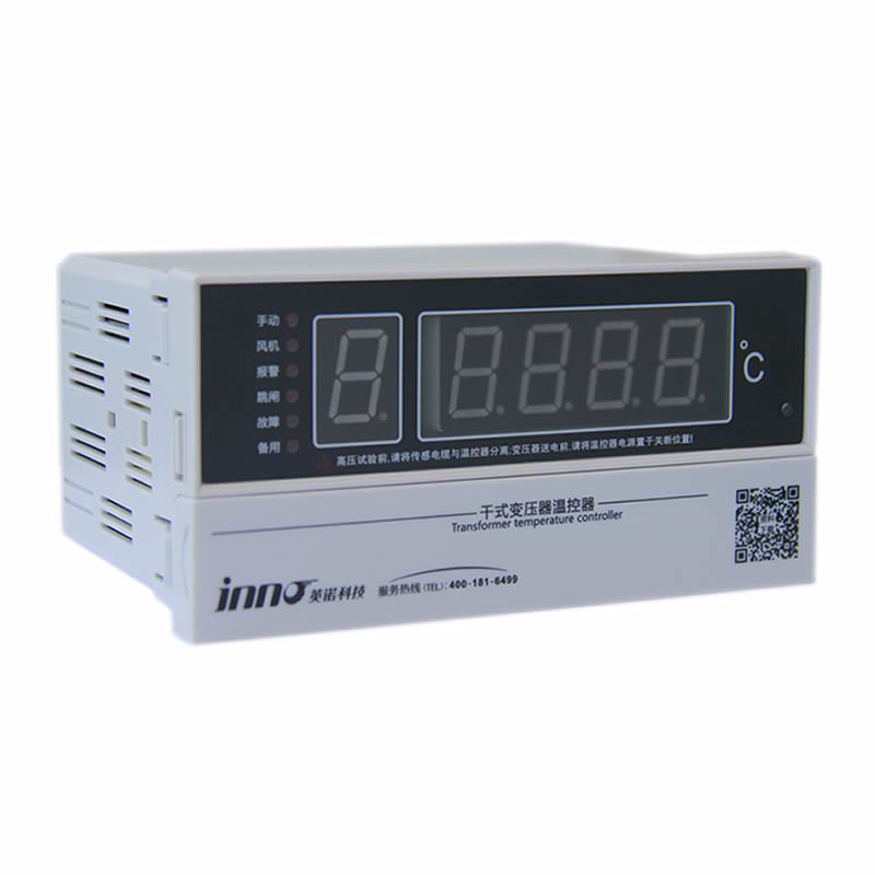
Метод 3: Thermal Simulation Oil Temperature Indicators (Индикаторы температуры обмотки)
Тем thermal simulation winding temperature indicator (WTI) — also known as a hot-spot temperature simulator или thermal image indicator — is a self-contained electromechanical instrument that estimates transformer winding hot-spot temperature using an analog thermal model of the transformer’s heat-rise behavior. It is one of the most widely installed transformer temperature monitoring devices in service globally, found on distribution and power transformers from 1 MVA to several hundred MVA.
Принцип работы
The WTI consists of a bimetallic dial thermometer installed in a PT100 oil temperature pocket on the transformer tank, combined with a small heating element energized by a current proportional to the transformer load current (supplied via a dedicated current transformer). The heater element mimics the I²R heat rise of the winding above oil temperature — so the thermometer pointer reads a temperature that represents the estimated winding hot spot rather than the oil temperature alone. By adjusting the heating current ratio and thermal time constant of the heater assembly, the WTI can be calibrated to closely match the actual winding thermal behavior defined in the transformer’s factory heat-run test report.
Функциональные особенности
- Provides a continuous estimated winding hot-spot temperature reading on a local analog dial — no external power supply required for basic indication
- Integral adjustable alarm and trip contacts (typically two independent contact stages) for direct connection to protection relay or SCADA alarm inputs
- Built-in drag-hand indicator records the maximum temperature reached since last manual reset — useful for post-event analysis of overload events
- Необязательный 4–20mA or PT100 analog output for remote monitoring integration
- Separate cooling control contacts for automatic fan or pump start/stop based on estimated hot-spot temperature
- Available in both индикатор температуры масла (СДЕЛАННЫЙ) конфигурация (measures top oil only, no load current input) и полный индикатор температуры обмотки (WTI) configuration with load current compensation
Applications and Limitations
Тем thermal simulation WTI is the standard temperature protection device on the majority of distribution and sub-transmission transformers in service worldwide due to its low cost, mechanical simplicity, and independence from external power supplies. Однако, its analog thermal model is a simplified representation of actual winding thermal behavior — it does not account for non-uniform current distribution, localized cooling variations, or changes in winding thermal characteristics due to insulation aging. For critical high-value transformers where accurate hot-spot knowledge is essential for life management and dynamic load optimization, direct fiber optic winding temperature measurement should supplement or replace WTI-based thermal simulation.
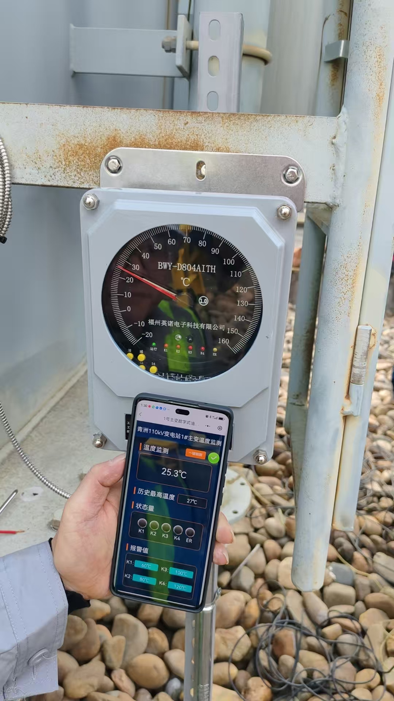
Метод 4: Wireless Temperature Monitoring Sensors
Wireless transformer temperature sensors use battery-powered transmitter nodes to collect surface temperature data at defined measurement points and relay readings to a central gateway or cloud monitoring platform via ЗигБи, Лора, 2.4GHz RF, or NB-IoT протоколы. This architecture eliminates signal cabling between the sensor and the monitoring system — a significant advantage for retrofit applications and installations where running new instrumentation cables to an existing transformer is impractical or costly.
Основные преимущества
- Tool-free installation on transformer external surfaces, вводные клеммы, LV busbar connections, and cable lugs
- Поддерживает multi-point networks covering dozens of measurement locations across a transformer bay or substation from a single gateway
- Real-time temperature data with configurable alarm thresholds and push notification to mobile devices or SCADA systems
- Идеально подходит для dry-type transformer enclosure monitoring where winding surface temperatures are the primary measurement target
- Cloud integration enables centralized monitoring and trending across multiple transformer installations on a single platform
Ограничения
Wireless sensors measure surface or near-surface temperatures only and cannot access the internal winding hot-spot of an oil-immersed transformer. Battery replacement is required typically every 2–5 years depending on transmission interval settings. Metal transformer enclosures attenuate radio frequency signals — antenna placement design and repeater positioning must be addressed during system commissioning to ensure reliable data transmission.
Метод 5: Инфракрасная термография
Infrared thermal imaging cameras detect the electromagnetic radiation emitted by transformer external surfaces and convert it into a calibrated visual heat map, enabling maintenance technicians to identify abnormal temperature gradients across bushings, клеммные соединения, cooling radiators, and tank surfaces during scheduled inspection visits without physical contact with energized equipment.
Handheld Infrared Camera vs. Fixed Online Thermal Sensor
Портативный infrared thermography cameras are the standard tool for periodic transformer inspection rounds and provide high-resolution thermal images suitable for maintenance reports and trend comparison across successive inspection cycles. Fixed online infrared sensors mounted in dedicated observation windows on transformer enclosures or switchgear panels enable continuous thermal monitoring of specific external zones — bridging the gap between scheduled inspection intervals for high-priority assets.
Core Advantages and Limitations
Infrared thermography excels as a бесконтактный, rapid survey tool for external fault detection and maintenance documentation. It is fully compatible with all transformer types and voltage levels and requires no permanent installation on the transformer itself. Однако, infrared measurement is fundamentally limited to surface temperature detection — it cannot measure winding hot-spot temperatures inside the transformer tank, and it provides only a periodic snapshot rather than the continuous real-time coverage needed for automated alarm and protection functions.
Мониторинг температуры трансформатора: Таблица сравнения технологий

| Критерии | Флуоресцентное оптоволокно | Датчик PT100 | Thermal Simulation WTI | Беспроводной датчик | Инфракрасная термография |
|---|---|---|---|---|---|
| Тип измерения | Direct winding hot spot | Масло / surface temperature | Estimated hot spot (рассчитанный) | Surface temperature | Surface temperature |
| Режим мониторинга | Непрерывный онлайн | Непрерывный онлайн | Непрерывный онлайн | Непрерывный онлайн | Периодический / scheduled |
| Устойчивость к электромагнитным помехам | ★★★★★ | ★★★ | ★★★★ | ★★★ | ★★★★ |
| Точность измерения | ±0,5°С | ±0.3–1°C | ±2–5°C (estimated) | ±1°С | ±2°С |
| Internal Winding Access | ✅ Direct | ❌ Surface only | ⚠️ Calculated estimate | ❌ Surface only | ❌ External only |
| Сигнализация в реальном времени | ✅ | ✅ | ✅ | ✅ | ❌ |
| Сложность установки | Умеренный (factory or retrofit) | Простой | Простой | Минимальный | Никто (портативный) |
| Suitable for Oil-Immersed | ✅ | ✅ | ✅ | ⚠️ External only | ✅ |
| Suitable for Dry-Type | ✅ | ✅ | ⚠️ Ограничено | ✅ | ✅ |
| МЭК 60076-2 Соответствует | ✅ | ⚠️ Indirect | ⚠️ Indirect | ❌ | ❌ |
| Лучшее приложение | Critical HV transformers, winding life management | Standard protection relay input, oil monitoring | Распределительные трансформаторы, routine thermal protection | Втулка, LV terminals, dry-type retrofit | Maintenance inspection, external fault survey |
7. Building the Best Transformer Thermal Monitoring System
The most effective решение для мониторинга температуры трансформатора is not a single device but a layered, integrated architecture that combines direct sensing, сбор данных, управление тревогами, and system-level integration to deliver actionable thermal intelligence throughout the transformer’s operating life.
Слой 1 — Зондирование: Matching Technology to Measurement Point
A comprehensive sensing deployment addresses all critical thermal zones of the transformer simultaneously. Флуоресцентные оптоволоконные зонды are embedded in the HV and LV winding assemblies at the factory-identified hot-spot locations to provide direct IEC 60076-2 compliant winding temperature readings. Датчики PT100 are installed in the tank cover oil pocket for top oil temperature measurement and in radiator inlet/outlet pipes for cooling system monitoring. A thermal simulation winding temperature indicator (WTI) устанавливается на распределительной панели трансформатора для обеспечения локальной электромеханической резервной индикации и независимых сигнальных контактов для срабатывания реле защиты.. Беспроводные датчики температуры применяются к проходным клеммным соединителям, НН шинные соединения, и кабельные наконечники для расширения зоны мониторинга внешних точек подключения высокого риска без дополнительных кабелей.
Слой 2 — Сбор данных
Волоконно-оптические сигналы обрабатываются многоканальный демодулятор флуоресценции который преобразует измерения времени оптического затухания в калиброванные значения температуры с частотой дискретизации 1–10 секунд.. Сигналы PT100 подаются непосредственно на реле защиты трансформатора. (например., АББ РЕТ670, Сименс 7УТ) или выделенному Входной модуль ТПС в системе управления подстанцией. Данные беспроводных датчиков агрегируются Шлюз LoRa или ZigBee mounted in the substation control room or marshalling kiosk.
Слой 3 — Communication and Integration
All temperature data streams converge at the substation automation system via МЭК 61850 GOOSE-сообщения for protection-grade alarm transmission, Modbus TCP/RTU for SCADA integration, и ДНП3 for utility EMS connectivity. Cloud-connected deployments use MQTT over 4G/5G for remote monitoring and mobile alerting without dependence on substation LAN infrastructure.
Слой 4 — Monitoring Platform and Alarm Management
Тем transformer thermal monitoring software platform provides real-time temperature dashboards for all sensing points, historical trend logging with configurable retention periods, and a three-tier alarm management structure. Консультативные сигналы тревоги at 95°C winding hot spot initiate automated cooling system escalation. Предупреждающие сигналы at 110°C trigger operator notification and load reduction procedures. Критические сигналы тревоги at 120°C (or the transformer manufacturer’s defined trip threshold) initiate automatic protection relay tripping to disconnect the transformer from service before thermal runaway occurs. All threshold values are configurable and should be validated against the transformer manufacturer’s thermal design data and the applicable loading guide (МЭК 60076-7 или IEEE C57.91).
Слой 5 — Automated Response and SCADA Integration
On alarm activation, the system executes a coordinated response sequence: cooling system fans and pumps are automatically started at full capacity; SMS, электронная почта, and push notifications are dispatched to designated operations personnel; load shedding commands are issued to upstream protection relays if temperature continues to rise; and at the critical threshold, an automatic trip command is executed. Full integration with СКАДА, EMS, КММС, и платформы управления активами ensures that all thermal events are logged with timestamped data, enabling post-event root cause analysis and regulatory compliance reporting.
Recommended System Configurations by Transformer Type
- Critical transmission transformer (≥100 МВА, 110кВ и выше): Fluorescent fiber optic winding sensors (factory-embedded, ВН + ЛВ) + PT100 top oil + WTI backup indicator + wireless bushing terminal sensors + full SCADA / МЭК 61850 интеграция
- Industrial oil-immersed transformer (10–100 МВА): Fluorescent fiber optic winding sensors + PT100 top oil and radiator monitoring + WTI with cooling control contacts + Modbus SCADA integration
- Dry-type cast-resin transformer: Флуоресцентные оптоволоконные зонды (embedded in winding during manufacture) + PT100 surface sensors + wireless LV busbar terminal sensors + local HMI display
- Distribution transformer retrofit: WTI replacement or upgrade + wireless surface sensors on bushing terminals + optional fiber optic probe insertion via tank cover port + cloud monitoring gateway
- Maintenance inspection program (all types): Periodic infrared thermographic surveys (minimum twice per year) combined with online monitoring data review for cross-validation and compliance documentation
8. Глобальные тематические исследования: Transformer Temperature Monitoring in Action

The following real-world deployments illustrate how системы теплового мониторинга трансформаторов have delivered measurable protection and operational value across a range of industries, уровни напряжения, and geographic regions.
Тематическое исследование 1 — Transmission Substation, Великобритания
A major UK transmission network operator retrofitted fluorescent fiber optic winding temperature sensors into twelve 400kV autotransformers at a critical grid interconnection substation. До установки, the operators relied exclusively on thermal simulation WTI indicators and top oil PT100 measurements — neither of which provided direct knowledge of actual winding hot-spot conditions under dynamic load cycling. Within the first operating season following fiber optic sensor commissioning, the monitoring system identified two units operating with winding hot-spot temperatures 18–23°C above the WTI-indicated values under peak demand conditions — a discrepancy attributable to thermal model parameter drift in aging units. Load management protocols were adjusted accordingly, and both transformers were scheduled for planned inspection rather than facing the risk of an unplanned thermal failure during peak winter demand. The operator estimated the intervention prevented outage costs in excess of £2 million per affected unit.
Тематическое исследование 2 — Data Center Campus, Сингапур
A hyperscale data center operator managing eight dry-type cast-resin transformers at a Tier IV facility deployed a hybrid monitoring architecture combining factory-embedded fluorescent fiber optic probes in each transformer’s HV and LV windings with a wireless temperature sensor network covering LV busbar connections, концевые наконечники кабеля, and main distribution board incoming terminals. Все 96 measurement points across the eight transformers feed into a centralized cloud monitoring platform with mobile push notifications configured for the facility’s 24/7 operations team. During a capacity expansion overload test eighteen months after commissioning, the fiber optic system detected a winding hot-spot temperature of 158°C in one transformer — 23°C above the WTI surface indication — triggering an immediate load transfer to the standby unit. Post-event thermal analysis confirmed that the affected transformer’s resin insulation had begun surface micro-cracking consistent with sustained overtemperature exposure, validating the system’s early intervention.
Тематическое исследование 3 — Rail Traction Power Substation, Китай
A metropolitan railway operator equipped traction power substations across 24 stations with multi-channel fluorescent fiber optic thermometry systems monitoring winding hot spots in Scott-connection traction transformers. The high-frequency switching transients and strong electromagnetic fields generated by traction inverter systems ruled out conventional PT100-based winding monitoring — electronic sensors in this environment experienced persistent measurement noise and false alarms. The all-optical fiber sensing architecture eliminated EMI-related false alarms entirely while delivering ±0.5°C winding hot-spot accuracy throughout the network. The system interfaces directly with the railway’s SCADA energy management system через МЭК 61850, enabling automated cooling control and load dispatch optimization based on real-time thermal headroom in each traction transformer.
Тематическое исследование 4 — Petrochemical Refinery, Саудовская Аравия
A major refinery operator managing fourteen 11kV oil-immersed unit transformers in classified hazardous area zones implemented a comprehensive monitoring upgrade combining ATEX-rated PT100 top oil sensors, thermal simulation WTI indicators with remote 4–20mA outputs, и intrinsically safe wireless temperature transmitters on transformer bushing terminals and HV cable termination boxes. The wireless network eliminated the need for new instrumentation cable runs through congested cable trays in the classified areas — a significant safety and cost advantage. The integrated monitoring platform flagged an abnormal bushing terminal temperature rise of 41°C above ambient on one transformer within six weeks of commissioning, leading to the discovery of a severely under-torqued terminal clamp that had been missed during the previous scheduled maintenance outage.
Тематическое исследование 5 — Wind Farm Collector Substation, Германия
A renewable energy developer commissioned a 250 MVA offshore wind farm collector transformer equipped with factory-embedded fluorescent fiber optic probes in both HV and LV windings, в сочетании с PT100 top oil sensors, radiator differential temperature monitoring, и WTI indicator providing independent local backup protection. The fiber optic system feeds real-time hot-spot data to the wind farm SCADA platform, enabling dynamic transformer loading optimization — allowing the operator to safely push transformer output above nameplate rating during periods of favorable ambient temperature and wind resource, while automatically curtailing generation when hot-spot temperatures approach the IEC 60076-7 emergency loading threshold. The dynamic loading capability increased annual energy yield by an estimated 3.2% compared to conservative fixed nameplate-limited operation.
Часто задаваемые вопросы: Мониторинг температуры трансформатора
1. Why is transformer temperature monitoring so important?
Transformer insulation — primarily cellulose paper in oil-filled units and cast resin in dry-type units — degrades irreversibly with heat exposure. According to the Arrhenius thermal aging model codified in IEC 60076-7, every 6–10°C of sustained overtemperature halves the remaining insulation life. Без continuous transformer temperature monitoring, thermal degradation proceeds invisibly until insulation failure causes an unplanned outage, огонь, or catastrophic transformer loss. Proactive monitoring enables condition-based maintenance, dynamic load management, and timely intervention before thermal damage becomes irreversible.
2. What is the difference between a winding temperature indicator (WTI) and a direct fiber optic winding sensor?
A thermal simulation winding temperature indicator (WTI) estimates winding hot-spot temperature using an analog thermal model — it measures top oil temperature and adds a calculated temperature increment proportional to load current. This estimate carries inherent uncertainty of ±2–5°C or more, particularly under dynamic load conditions or when the transformer’s thermal characteristics have changed due to aging. A fluorescent fiber optic winding sensor measures the actual temperature at the physical hot-spot location inside the winding — providing a direct, real-time reading with ±0.5°C accuracy that requires no thermal model assumptions. For critical high-value transformers, direct fiber optic measurement provides significantly higher confidence in thermal condition assessment than WTI simulation alone.
3. What temperature should trigger a transformer winding alarm?
Alarm thresholds depend on transformer insulation class, design rating, and applicable loading standard. For standard mineral-oil transformers with Class A cellulose insulation, МЭК 60076-7 defines a continuous hot-spot limit of 98°C for normal cyclic loading, с emergency loading limits up to 140°C for short-duration contingency operation. Typical protection relay settings use a first-stage alarm at 100–110°C winding hot spot to initiate cooling escalation and operator notification, с second-stage trip at 120–130°C to automatically disconnect the transformer. For dry-type cast-resin transformers, thermal class F (155°С) and class H (180°С) windings carry higher permissible operating temperatures — consult the transformer manufacturer’s documentation for model-specific settings.
4. Can fluorescent fiber optic probes be retrofitted into an existing oil-immersed transformer?
Да, in many cases. Retrofit installation of fluorescent fiber optic sensors in existing oil-immersed transformers is technically feasible during planned maintenance outages when the transformer is de-energized and oil drained or partially lowered. Probes are inserted through the transformer tank cover via dedicated fiber feedthrough fittings and guided into the winding assembly using flexible insertion tools. The specific feasibility depends on winding construction, available tank access points, and the transformer manufacturer’s guidance. For new transformer procurement, specifying factory-installed fiber optic probes during manufacture is the preferred approach as it ensures optimal sensor placement at the design hot-spot location.
5. What is the difference between top oil temperature and winding hot-spot temperature?
Верхняя температура масла is the temperature of the insulating oil at the highest point in the transformer tank — measured by a Датчик PT100 in the tank cover pocket. It represents the bulk thermal state of the transformer’s cooling medium. Winding hot-spot temperature is the highest temperature point within the winding conductor and insulation assembly — typically located in the upper portion of the coil and consistently higher than the surrounding oil temperature by 15–40°C depending on load level and cooling mode. It is the winding hot-spot temperature, not the top oil temperature, that directly governs insulation aging rate and permissible loading capacity. Relying on top oil temperature alone systematically underestimates the thermal stress on transformer insulation.
6. Do transformer temperature monitoring systems need to comply with IEC standards?
Да. The primary applicable standards for контроль температуры трансформатора являются МЭК 60076-2 (Temperature rise for liquid-immersed transformers — defines hot-spot measurement methodology), МЭК 60076-7 (Loading guide for oil-immersed power transformers — defines thermal aging model and loading limits), и МЭК 60354 (Loading guide for oil-immersed power transformers, superseded by IEC 60076-7 but still referenced). Для сухих трансформаторов, МЭК 60076-11 applies. Protection relay and monitoring system integration follows МЭК 61850 for substation automation communication. Buyers should confirm that proposed monitoring systems are designed to these standards and that sensor accuracy and calibration traceability are documented accordingly.
7. Is wireless temperature monitoring suitable for use inside oil-immersed transformer tanks?
Нет. Беспроводные датчики температуры are electronic devices that require a battery power source and radio frequency signal transmission — neither of which is compatible with the interior of an energized oil-filled transformer tank. Wireless sensors are appropriate for external transformer surface monitoring applications: bushing terminal connections, НН шинные соединения, cable termination boxes, and dry-type transformer enclosure surfaces. For internal winding hot-spot monitoring of oil-immersed transformers, флуоресцентные оптоволоконные датчики are the only technology that can be safely installed inside the energized transformer tank.
8. How long do fluorescent fiber optic temperature sensors last in transformer service?
Fluorescent fiber optic sensing probes are passive optical components with no active electrical elements, движущиеся части, or consumable materials at the sensing point. Under normal transformer operating conditions — including continuous immersion in mineral oil, thermal cycling between ambient and rated hot-spot temperatures, and exposure to dissolved gases and moisture — documented field service lifetimes exceed 20–25 years without degradation of measurement accuracy or sensor integrity. The external demodulator electronics have a typical design life of 10–15 years with routine maintenance. This long service life makes fiber optic sensing a cost-effective investment over the full operational life of the transformer asset.
9. Can a transformer temperature monitoring system integrate with existing SCADA or EMS platforms?
Да. All major системы теплового мониторинга трансформаторов support the standard industrial communication protocols required for SCADA, EMS, and substation automation integration. Common supported protocols include МЭК 61850 (GOOSE and MMS) for protection-grade substation communication, Modbus RTU/TCP for general SCADA connectivity, ДНП3 for utility EMS and telecontrol systems, и MQTT over 4G/5G for cloud-based remote monitoring deployments. Интеграция с computerized maintenance management systems (КММС) и digital asset management platforms enables automatic work order generation on alarm events and continuous trending of transformer thermal health indicators alongside other condition monitoring data streams.
10. How do I select the best transformer temperature monitoring solution for my specific application?
The optimal solution depends on four primary factors. Первый, transformer type and voltage level: oil-immersed units above 10kV benefit most from direct fiber optic winding monitoring; dry-type units are well served by embedded fiber optic probes combined with wireless surface sensors. Второй, criticality and replacement cost: transmission transformers above 100 MVA with 12–24 month replacement lead times justify comprehensive fiber optic monitoring; distribution transformers may be adequately protected by WTI plus PT100 with periodic infrared inspection. Третий, new build vs. модернизировать: factory-embedded fiber optic probes are the most cost-effective approach for new transformers; retrofit projects should evaluate the feasibility of probe insertion versus wireless external monitoring as the primary upgrade path. Четвертый, integration requirements: facilities with existing SCADA or IEC 61850 substation automation infrastructure should specify monitoring systems with native protocol support to avoid costly middleware integration. Contact a specialist transformer monitoring supplier to obtain a site-specific system recommendation based on your transformer nameplate data, профиль загрузки, и цели мониторинга.
Get the Right Transformer Temperature Monitoring Solution for Your Project
Whether you are commissioning a new high-voltage power transformer, upgrading protection on aging critical assets, or building a fleet-wide thermal monitoring program across multiple substations, подбор правильного сочетания флуоресцентные оптоволоконные датчики, Детекторы PT100, thermal simulation indicators, и технология беспроводного мониторинга это решение, которое напрямую влияет на долговечность трансформатора, Эксплуатационная надежность, и безопасность персонала.
ФДЖИННО (Инновационный электронный научный центр Фучжоу&Технологическая компания, ООО) специализируется на системы контроля температуры люминесцентного оптоволоконного трансформатора с более чем десятилетним опытом развертывания высоковольтных распределительных устройств, Силовые трансформаторы, ГИС-оборудование, трансформаторы сухого типа, и железнодорожные тяговые энергосистемы. Наша команда инженеров обеспечивает проектирование системы для конкретного применения., заводская калибровка, поддержка установки, и долгосрочное техническое обслуживание проектов любого масштаба — от модернизации защиты одного трансформатора до программ мониторинга энергосистем на нескольких объектах..
- 📧 Отправить по электронной почте: web@fjinno.net
- 📱 Ватсап / Веб-чат / Телефон: +86 135 9907 0393
- 💬 КК: 3408968340
- 🌐 Сайт: www.fjinno.net
- 📍 Адрес: Промышленный парк Liandong U Grain Networking, № 12 Синъе Вест Роуд, Фучжоу, Фуцзянь, Китай
Отказ: Техническая информация, температурные пороги, и стандартные ссылки в этой статье предназначены только для общих целей.. Специальные настройки защиты трансформатора, характеристики датчика, and system configurations must be determined by qualified electrical engineers in accordance with the transformer manufacturer’s documentation, applicable IEC and IEEE standards, и местные нормативные требования. Always follow established safety procedures when working on or near energized electrical equipment.

Волоконно-оптический датчик температуры, Интеллектуальная система мониторинга, Производитель распределенного оптоволокна в Китае
 |
 |
 |