 Оптоволоконные датчики температуры INNO ,системы контроля температуры.
- Трансформаторы подстанций с расширенными функциями контроля температуры использовать встроенные флуоресцентные оптоволоконные датчики для измерения температуры в горячих точках обмотки, верхняя температура масла, внутренняя температура, температура ввода, и температура контакта переключателя ответвлений в режиме реального времени — заменяя или дополняя традиционные косвенные методы.
- Флуоресцентные оптоволоконные датчики температуры являются единственной технологией, которую можно безопасно встроить непосредственно в обмотки высоковольтных трансформаторов, поскольку они полностью неметаллические., непроводящий, и невосприимчив к интенсивным электромагнитным полям, присутствующим внутри трансформатора под напряжением..
- Непосредственное измерение горячих точек обмотки исключает ошибки оценки, присущие обычным индикаторам температуры обмотки. (нефть марки WTI), обеспечивая более точную тепловую защиту, более длительный срок службы изоляции, и уверенная динамическая грузоподъемность.
- Полная система мониторинга состоит из оптоволоконные датчики температуры, optical fiber cables routed through transformer bushings or feedthroughs, a multi-channel оптоволоконный демодулятор, and software that integrates with substation SCADA, DCS, и платформы управления активами.
- Applications span power transformers from 110 кВ до 800 кВ, распределительные трансформаторы, тяговые трансформаторы, industrial furnace transformers, offshore wind step-up transformers, and data center critical-supply transformers.
Оглавление
- What Is Advanced Temperature Monitoring for Substation Transformers
- Why Substation Transformers Need Temperature Monitoring
- Key Temperature Monitoring Points in a Transformer
- Limitations of Traditional Temperature Monitoring Methods
- Как работают флуоресцентные оптоволоконные датчики температуры
- Advantages of Fiber Optic Sensors for Transformer Monitoring
- Fiber Optic vs Traditional Sensors — A Detailed Comparison
- System Architecture of an Advanced Monitoring Solution
- Application Scenarios Across Transformer Types
- FAQs About Substation Transformer Temperature Monitoring
1. Что такое Advanced Temperature Monitoring for Substation Transformers

Definition and Background
Substation transformer temperature monitoring refers to the continuous, real-time measurement of temperature at multiple critical locations inside and on the surface of power transformers installed in electrical substations. Advanced monitoring goes beyond legacy instruments by embedding sensors directly at the points where thermal stress is greatest — within the high-voltage and low-voltage windings themselves — to capture true hot-spot temperatures rather than relying on indirect estimation. The enabling technology behind this advancement is the флуоресцентный оптоволоконный датчик температуры, which can operate safely inside the high-voltage, oil-filled, electromagnetically intense environment of an energized transformer.
From Traditional Measurement to Intelligent Monitoring
На протяжении десятилетий, transformer operators relied on top-oil thermometers and winding temperature indicators (нефть марки WTI) that inferred winding temperature from oil temperature plus a simulated thermal image current. While these instruments provided a basic level of protection, they could not measure actual winding hot-spot temperature directly. The introduction of fiber optic sensing technology transformed this situation by making it possible, for the first time, to place sensors in direct contact with conductor insulation deep inside the winding structure. This shift from estimation to direct measurement represents the defining characteristic of advanced системы теплового мониторинга трансформаторов.
Strategic Value in the Modern Power Grid
As electrical grids face increasing load demands, более высокое проникновение возобновляемой генерации, и стареющий парк трансформаторов, потребность в точной тепловой разведке стала критической. Усовершенствованный мониторинг температуры позволяет коммунальным предприятиям с уверенностью эксплуатировать трансформаторы ближе к их истинным тепловым пределам., отсрочить дорогостоящие замены за счет технического обслуживания по состоянию, и предотвратить катастрофические тепловые сбои, которые могут вызвать массовые отключения электроэнергии и ущерб окружающей среде.. Трансформаторы подстанций с расширенными функциями контроля температуры больше не являются премиальным вариантом — они становятся базовым требованием для надежности современной сети..
2. Why Substation Transformers Need Temperature Monitoring

Термический отказ является основной причиной выхода из строя трансформатора
Статистика отказов в отрасли неизменно показывает, что термическая деградация является основным механизмом, приводящим к окончанию срока службы трансформатора и неожиданным отказам.. Устойчивые условия перегрева — вызваны ли они перегрузкой, неисправность системы охлаждения, заблокирован поток масла, или внутренние неисправности — ускоряют разрушение целлюлозной изоляции и ухудшают диэлектрические свойства трансформаторного масла.. Одна необнаруженная горячая точка может инициировать цепочку событий, ведущих от карбонизации изоляции до частичного разряда., межвитковое короткое замыкание, и, в конечном итоге, катастрофический отказ, включая пожар или разрыв резервуара..
Срок службы изоляции и зависимость температуры
Ожидаемый срок службы изоляции трансформатора находится в экспоненциальной зависимости от температуры.. Согласно установленным моделям термического старения, каждый 6 °С до 7 °C Увеличение устойчивой температуры в горячей точке выше номинального значения сокращает срок службы изоляции примерно 50 процент. Наоборот, operating a transformer even a few degrees below its rated hot-spot limit can significantly extend the useful life of the asset. Точный, в реальном времени Температура горячей точки обмотки трансформатора measurement is therefore directly linked to the economic value and remaining useful life of the transformer.
Load Management and Dynamic Rating
Under conventional practice, transformers are loaded according to nameplate ratings that assume worst-case ambient conditions and conservative thermal models. When actual operating temperatures are known in real time through direct measurement, operators can apply dynamic transformer rating — adjusting allowable load based on true thermal conditions rather than conservative assumptions. This can unlock 10 к 30 percent additional capacity from existing transformers during periods of favorable ambient temperature or lower-than-expected losses, deferring the need for expensive new installations.
Compliance and Asset Management Requirements
Регуляторы коммунальных услуг, insurance providers, and grid reliability standards increasingly require documented evidence of transformer thermal condition. МЭК 60076-7 and IEEE C57.91 both provide guidance on hot-spot temperature limits and thermal loading calculations that depend on accurate temperature input data. Advanced monitoring systems provide the auditable, time-stamped records needed to demonstrate compliance and support data-driven asset management decisions.
3. Ключ Temperature Monitoring Points in a Transformer
![]()
Температура горячей точки обмотки

The температура горячей точки обмотки is the single most critical thermal parameter of any power transformer. It occurs at the location within the winding where the combination of resistive losses (I²R), eddy current losses, and local oil flow conditions produces the highest temperature. This point is typically located in the upper portion of the innermost winding disc or layer, where oil circulation is most restricted. Direct measurement of the winding hot spot using embedded оптоволоконные датчики температуры is the gold standard for transformer thermal assessment because it captures the actual worst-case temperature without relying on thermal models or correction factors.
Top-Oil Temperature
Top-oil temperature is measured in the oil space at the top of the transformer tank, typically near the oil outlet to the radiator bank. It reflects the bulk thermal state of the transformer and is used as an input to cooling control logic. While top-oil measurement has been standard practice for decades, it alone cannot reveal localized winding hot spots. Оптоволоконные датчики positioned in the oil space provide accurate, interference-free top-oil readings that complement embedded winding measurements.
Температура ядра
Transformer core hot spots can develop due to concentrated flux density at the edges of laminations, at bolt holes, or near core clamps. Localized core overheating can damage interlaminar insulation and lead to circulating currents that generate additional heat. Оптоволоконные датчики температуры attached to core surfaces at identified risk areas detect thermal anomalies before they progress to core damage.
Bushing and Terminal Temperature
Transformer bushings carry full load current through the tank wall and are subject to resistive heating, especially at the internal conductor connection point. Bushing temperature monitoring detects deteriorating contact resistance, loss of insulating oil in condenser bushings, and other conditions that can lead to bushing failure — one of the most common and dangerous transformer fault modes. Fiber optic sensors installed at the base of the bushing inside the tank provide direct temperature data unaffected by external weather conditions.
Tap Changer Contact Temperature
Переключатели ответвлений под нагрузкой (устройства РПН) are the most mechanically active component of a transformer and a frequent source of thermal problems. Worn or contaminated selector contacts develop high resistance, producing localized heating that can carbonize oil and generate combustible gases. Tap changer temperature sensors based on fiber optic technology monitor contact temperature continuously, providing early warning of developing contact degradation before it leads to OLTC failure.
Cooling System Temperature
Oil inlet and outlet temperatures across radiator banks, oil-to-water heat exchangers, and forced-air cooling assemblies indicate cooling system effectiveness. Monitoring these temperatures with fiber optic sensors helps detect blocked radiators, failed fan motors, pump failures, or loss of cooling water flow — any of which can cause rapid transformer overheating.
4. Limitations of Traditional Temperature Monitoring Methods
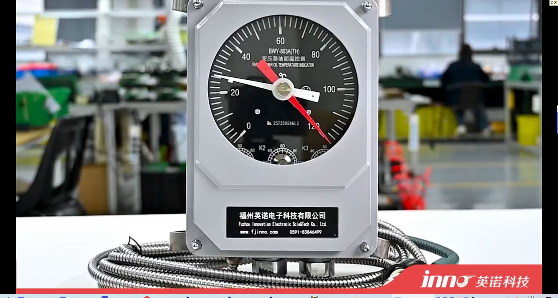
Индикаторы температуры обмотки (WTI) — Indirect and Inaccurate
The conventional WTI uses a thermal image technique: a current transformer supplies a scaled current to a heater element immersed in an oil-filled pocket, and the resulting temperature rise above top-oil is assumed to represent the winding hot-spot rise. This method introduces multiple sources of error — the thermal model is a simplification of actual winding thermal behavior, the oil pocket response time is slow, and the calibration assumes a fixed loss ratio that does not hold under all loading conditions. Studies have shown that WTI readings can deviate from actual winding hot-spot temperature by 10 °С до 20 °C or more, leading to either under-protection or unnecessary load curtailment.
Thermocouples and RTDs — Electromagnetic Interference
Thermocouples and resistance temperature detectors (РДД) use metallic sensing elements and lead wires. Inside an energized transformer, these metallic components are exposed to intense alternating magnetic fields generated by the windings and core. The resulting electromagnetic interference induces noise voltages in the sensor circuit that can cause measurement errors of several degrees or more. Кроме того, metallic sensor leads inside a high-voltage winding create the risk of insulation breakdown and dielectric failure along the lead path — an unacceptable safety hazard in high-voltage transformers.
Infrared Thermography — Surface Limitation
Infrared thermal imaging is a valuable tool for external inspection of transformers, identifying hot connections, blocked radiator sections, and abnormal tank surface temperatures. Однако, infrared thermography cannot see through the steel tank wall to measure internal winding, основной, or oil temperatures. It provides only a surface view and is influenced by emissivity variations, ambient reflections, ветер, and solar radiation. It serves as a complementary inspection technique but cannot replace embedded real-time monitoring.
Inability to Achieve Continuous Online Monitoring
Traditional methods share a common limitation: they cannot provide continuous, точный, real-time winding hot-spot temperature data. WTIs offer an approximation. Thermocouples are unsafe for high-voltage embedding. Infrared imaging requires manual inspection visits. None of these approaches supports the automated, continuous monitoring that modern grid operations and condition-based maintenance strategies demand.
5. Как Флуоресцентные оптоволоконные датчики температуры Работа
Fluorescence Lifetime Decay Measurement Principle
А флуоресцентный оптоволоконный датчик температуры operates on the principle of photoluminescence decay. The sensing probe tip is coated with a rare-earth doped phosphor crystal. A short pulse of excitation light is transmitted from the оптоволоконный демодулятор through the optical fiber to the probe tip, where it stimulates the phosphor to emit fluorescent light. After the excitation pulse ends, флуоресценция не прекращается мгновенно — она затухает экспоненциально с характерной постоянной времени, которая является точной, повторяемый, и монотонная функция температуры люминофора. Демодулятор измеряет это время затухания с высокой точностью и преобразует его в калиброванные показания температуры..
Полностью оптическая сигнальная цепь — от пробника до демодулятора
Весь путь измерения — от люминофорного наконечника оптоволоконный датчик температуры встроенный в обмотку трансформатора, через оптоволоконный кабель, выведенный из трансформатора через оптоволоконный ввод в стенке резервуара, к оптоволоконный демодулятор расположен в шкафу управления подстанции — чисто оптический. В сенсорной цепи отсутствуют электрические сигналы.. В точке измерения или рядом с ней внутри трансформатора отсутствуют металлические проводники.. This all-optical architecture is the fundamental reason fiber optic sensors can operate safely and accurately inside high-voltage, electromagnetically intense transformer environments.
Why Decay Time Is Superior to Intensity Measurement
Some earlier optical sensing approaches attempted to measure temperature through changes in fluorescence intensity. Intensity-based methods are inherently unreliable because signal amplitude is affected by fiber bending, потери в разъеме, light source aging, and contamination of optical surfaces. By measuring the time domain characteristic — the fluorescence decay time — rather than amplitude, the sensor becomes immune to all of these signal level variations. This gives fluorescent fiber optic sensors their exceptional long-term measurement stability without the need for periodic recalibration.
Intrinsic Safety of the Optical Approach
Because the fiber optic probe contains no metal, no electrical current, and no stored electrical energy, it presents zero ignition risk inside the oil-filled transformer tank. It does not create a conductive path that could compromise the dielectric integrity of the winding insulation system. The sensor is intrinsically safe by nature of its physics — not by addition of safety barriers or protective enclosures.
6. Advantages of Fiber Optic Sensors for Transformer Monitoring

Complete Immunity to Electromagnetic Interference and High-Voltage Fields
Inside an energized power transformer, the magnetic flux density can reach several Tesla, and the electric field gradient around high-voltage windings is extreme. Флуоресцентные оптоволоконные датчики температуры are constructed entirely from non-conductive glass, керамический, and polymer materials. They do not interact with magnetic fields, electric fields, или радиочастотная энергия любым способом. Точность измерения остается постоянной независимо от уровня нагрузки трансформатора., текущие события неисправности, или переключение переходных процессов. Полная невосприимчивость к электромагнитным помехам является самым важным преимуществом оптоволоконной технологии в контроль температуры трансформатора подстанции.
Электрическая изоляция — датчик и обмотка высокого напряжения безопасно сосуществуют
Встраивание любого датчика в обмотку трансформатора, работающего при напряжении в десятки или сотни киловольт, требует абсолютной электрической изоляции между датчиком и любым заземленным оборудованием.. Оптическое волокно само по себе является идеальным изолятором: его диэлектрическая стойкость превышает класс напряжения любого силового трансформатора, эксплуатируемого сегодня.. Никаких дополнительных изоляционных барьеров., делители напряжения, или необходимы устройства гальванической развязки. The fiber optic cable passes through a dedicated feedthrough fitting in the transformer tank wall, maintaining the pressure seal and insulation integrity of the tank.
Direct Measurement of True Winding Hot-Spot Temperature
Because fiber optic probes are physically small, непроводящий, and do not disturb the winding’s electromagnetic or thermal behavior, they can be placed directly at the predicted hot-spot location during winding manufacture. This yields a direct measurement of the actual hottest point in the winding — not an estimate, not a simulation, and not an inference from oil temperature. Direct hot-spot measurement transforms the accuracy and confidence level of all thermal protection, загрузка, and life assessment decisions.
Oil-Compatible, Высокотемпературный, Long-Term Stable
Fiber optic probes are encapsulated in materials fully compatible with mineral transformer oil, натуральный эфир, and synthetic ester insulating fluids. They withstand continuous operating temperatures well above the thermal limits of transformer insulation materials. The fluorescence decay measurement principle has no inherent drift mechanism — sensors installed during transformer manufacture maintain their calibration accuracy throughout the full service life of the transformer without recalibration.
Compact Size — No Impact on Transformer Internal Design
Типичный оптоволоконный датчик температуры for transformer winding embedding has an outer diameter of approximately 1 к 2 mm and a sensing length of just a few millimeters. The optical fiber cable has a similarly small cross-section. These dimensions allow the sensor and cable to be routed between winding turns or along insulation spacers without affecting oil flow channels, insulation distances, or mechanical clamping pressure.
Extended Service Life and Minimal Maintenance
Fiber optic temperature sensors have no moving parts, no electrical connections inside the transformer, and no consumable components. Field experience spanning more than two decades has demonstrated service lives exceeding 25 years — matching or exceeding the design life of the transformer itself. Maintenance is limited to periodic inspection of the external fiber optic connectors and demodulator, both of which are located outside the transformer in the easily accessible substation control environment.
7. Fiber Optic vs Traditional Sensors — A Detailed Comparison

Fiber Optic vs Winding Temperature Indicator (WTI)
The WTI provides an estimated winding temperature based on a thermal image model that assumes fixed thermal relationships. It cannot adapt to changing oil flow conditions, non-uniform losses, or aging effects. А оптоволоконный датчик температуры embedded at the actual hot spot measures the real temperature with an accuracy of ±1 °C or better, delivering a direct reading that is inherently more trustworthy for protection, решения по загрузке, and remaining life calculations.
Fiber Optic vs Thermocouple and RTD
Thermocouples and RTDs cannot be safely embedded in high-voltage windings due to the risk of dielectric failure along metallic lead wires and the severe electromagnetic interference that degrades measurement accuracy. Fiber optic sensors eliminate both hazards entirely. Their non-conductive, неметаллическая конструкция делает их единственным типом датчиков, одобренным крупнейшими производителями трансформаторов и международными стандартами для установки с прямой обмоткой..
Волоконно-оптическая термография против инфракрасной термографии
Инфракрасная термография ограничивается измерениями внешних поверхностей и требует посещения вручную или фиксированных камер с доступом на прямую видимость.. Он не может измерить обмотку, основной, или внутренняя температура масла. Оптоволоконные трансформаторные датчики предоставлять непрерывные данные о внутренней температуре 24 часов в день, 365 дней в году, независимо от погоды, освещение, или условия доступа.
Подробная сравнительная таблица
| Параметр | Волоконно-оптический датчик | WTI | Термопара / РТД | Инфракрасное изображение |
|---|---|---|---|---|
| Тип измерения | Прямая точка доступа | Оцененный (тепловое изображение) | Прямой (ограниченное количество мест) | Только внешняя поверхность |
| Встраивание обмотки | Да — безопасно для всех классов напряжения | Непригодный | Небезопасно на уровнях высокого напряжения | Невозможно |
| Устойчивость к электромагнитным помехам | Полный | Умеренный | Бедный | Непригодный |
| Диэлектрическая безопасность | Неотъемлемый — полностью диэлектрический | Непригодный | Риск разрушения изоляции | Непригодный |
| Точность | от ±0,5 до ±1 °C | от ±5 до ±15 °C | от ±1 до ±3 °C (когда нет помех) | ±2 to ±5 °C |
| Непрерывный мониторинг | Да - 24/7 онлайн | Yes — with limited accuracy | Yes — with EMI limitations | No — periodic or fixed-camera |
| Совместимость масел | Полный | Sealed pocket | Limited — requires sealing | Непригодный |
| Срок службы | 25+ годы | 15–20 years | 5–10 лет | Camera dependent |
| Обслуживание | Минимальный | Периодическая калибровка | Regular inspection | Очистка линз, калибровка |
8. System Architecture of an Advanced Monitoring Solution
![]()
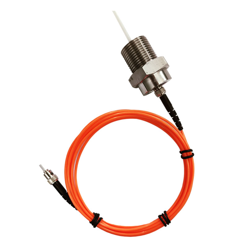
Волоконно-оптический датчик температуры Selection and Installation
Оптоволоконные датчики температуры for transformer applications are manufactured in several configurations. Winding-embedded probes are designed with a flat, thin profile that fits between conductor turns or along insulation spacers. Surface-mount probes with adhesive or mechanical fixation are used for core, tank wall, and bushing base measurement. Probes for oil temperature measurement are housed in stainless steel thermowells installed in standard tank fittings. During transformer manufacture, probes are installed at the factory and their fiber cables are routed through the winding structure and out of the tank through dedicated fiber optic feedthroughs — hermetically sealed fittings that maintain the transformer’s oil and gas integrity.
Fiber Optic Transmission Cable
The optical fiber cable connecting each probe to the demodulator is a single-strand or multi-strand glass fiber with protective buffer and jacket layers selected for compatibility with transformer oil inside the tank and for UV resistance, moisture protection, and mechanical durability outside the tank. Cable routing from the tank wall feedthrough to the demodulator in the substation relay room typically uses armored or conduit-protected fiber cable rated for outdoor substation environments.
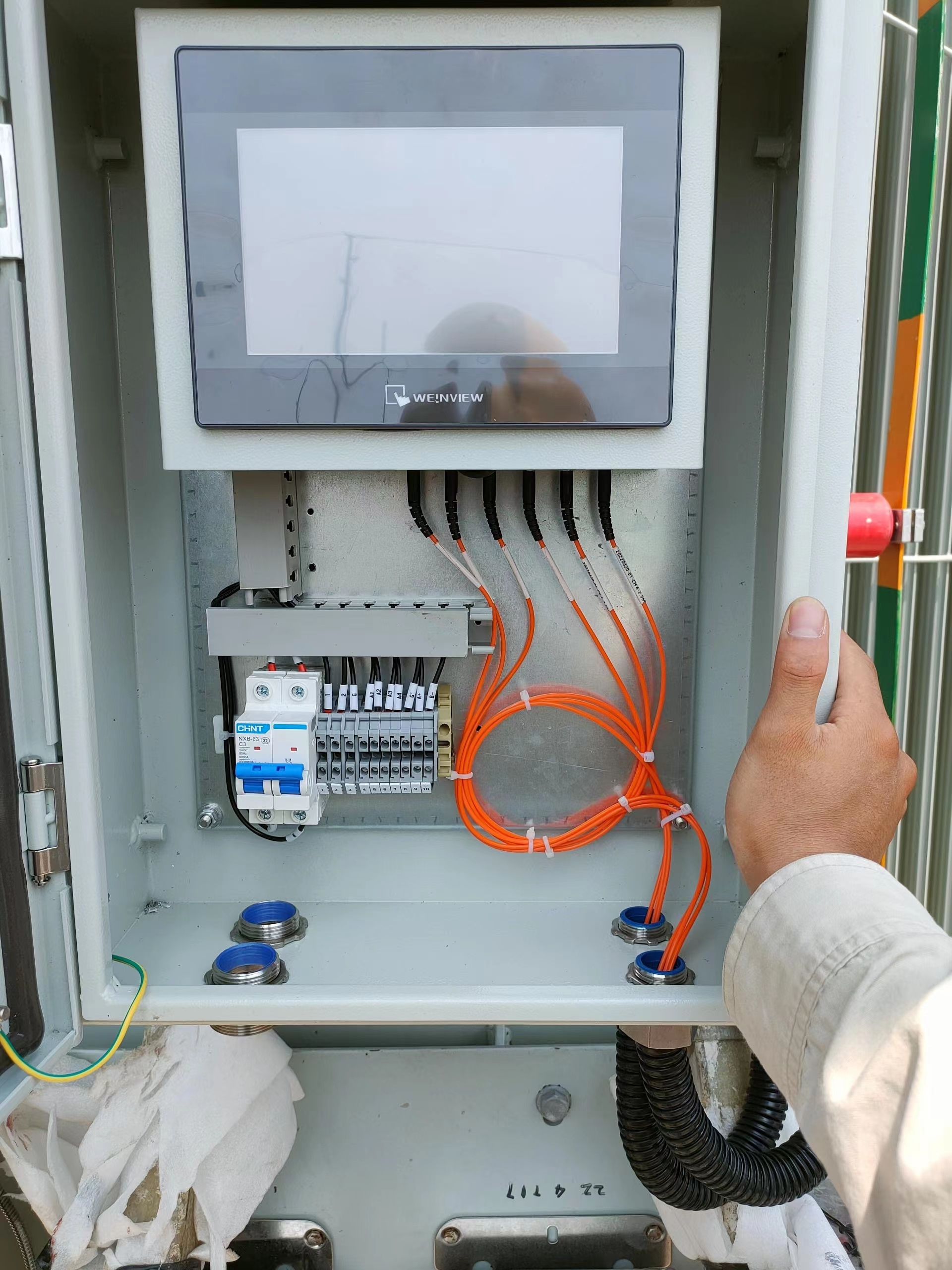
Fiber Optic Demodulator — Multi-Channel Signal Processing
The оптоволоконный демодулятор is the central instrumentation unit. It generates precisely timed excitation light pulses, captures the fluorescent return signal from each probe, digitally processes the decay waveform to extract temperature, and outputs calibrated readings on all channels simultaneously. Industrial-grade demodulators designed for substation environments support 4, 8, 16, or more measurement channels and are built to operate reliably across the wide ambient temperature range, уровень влажности, and electromagnetic conditions encountered in substation control rooms and marshalling kiosks.
Communication Interfaces and Substation Automation Integration
Modern demodulators provide multiple communication interfaces to support integration with substation automation systems. Стандартные выходы включают аналоговые сигналы 4–20 мА для устаревших релейных входов., Последовательный порт RS485 с протоколом Modbus RTU, Ethernet с Modbus TCP или IEC 61850 ММС, и релейные контактные выходы для функций сигнализации и отключения.. МЭК 61850 интеграция особенно важно для новых цифровых подстанций, позволяя системе мониторинга температуры публиковать данные в виде сообщений GOOSE или как часть структуры логического узла подстанции для прямого потребления защитными интеллектуальными электронными устройствами., контроллеры отсеков, и станция SCADA HMI.
Программное обеспечение для мониторинга и платформа управления данными
Специальное программное обеспечение для мониторинга предоставляет информационные панели в режиме реального времени, отображающие все температурные каналы., диаграммы трендов, показывающие тепловую историю за несколько часов, дни, и месяцы, настраиваемые пороги тревоги с логикой эскалации, и автоматическое создание отчетов для целей регулирования и управления активами.. Advanced platforms incorporate thermal models compliant with IEC 60076-7 and IEEE C57.91, allowing the software to compute remaining insulation life consumption, dynamic load capacity, and predicted time to hot-spot temperature limit based on current loading trajectory. Historical temperature data is archived and can be exported to utility enterprise asset management (EAM) системы, historian databases, и облачные аналитические платформы.
9. Application Scenarios Across Transformer Types
High-Voltage Power Transformers (110 кВ – 800 кВ)
Large power transformers in transmission substations are the most critical and expensive single assets in the electrical grid. A single transformer can cost several million dollars and have a lead time of one to two years for replacement. Встраивание флуоресцентные оптоволоконные датчики температуры in the HV, ЛВ, and tertiary windings during manufacture provides the most comprehensive thermal intelligence available. Утилиты используют эти данные для входа реле защиты., динамический рейтинг для управления периодами пиковой нагрузки, и планирование технического обслуживания с учетом состояния для продления срока службы активов. Для трансформаторов номиналом 220 кВ и выше, Прямое измерение горячих точек оптоволокна все чаще указывается в качестве стандартного требования в спецификациях на закупки..
Распределительные трансформаторы
Хотя отдельные распределительные трансформаторы требуют меньших капиталовложений., огромное количество единиц техники в парке коммунальных предприятий и растущая нагрузка от зарядки электромобилей, тепловые насосы, и распределенная генерация создают новые проблемы управления температурным режимом. Оптоволоконный мониторинг ключевых распределительных трансформаторов на сильно нагруженных фидерах предоставляет данные для прогнозирования нагрузки., сетевое планирование, и целенаправленное усиление. Компактный, экономичные многоканальные демодуляторы делают мониторинг экономически выгодным для этого уровня приложений..
Traction Transformers for Railway Electrification
Traction transformers in railway substations experience highly dynamic and cyclical loading profiles as trains accelerate, cruise, and regenerate. These load transients produce rapid winding temperature fluctuations that WTIs cannot track accurately. Оптоволоконные датчики температуры with fast response times capture these transients in real time, enabling precise thermal protection and supporting the dynamic rating needed to maximize train frequency on busy routes.
Rectifier Transformers and Electric Arc Furnace Transformers
Industrial transformers supplying DC rectifiers and electric arc furnaces operate under extreme conditions — high harmonic content, heavy overloads, и частая циклическая нагрузка. Harmonic currents generate additional eddy current losses in the windings that elevate hot-spot temperature above values predicted by standard thermal models. Direct fiber optic hot-spot measurement provides the true thermal picture, protecting these transformers from premature insulation aging and enabling operators to optimize furnace duty cycles.
Offshore Wind and Renewable Energy Step-Up Transformers
Transformers installed on offshore wind turbine platforms or in onshore collector substations face unique challenges — remote location, limited access for maintenance, harsh marine environments, and variable generation profiles. Fiber optic transformer monitoring provides continuous thermal data without requiring site visits, supports remote diagnostics, and feeds into wind farm SCADA systems for centralized fleet management. The maintenance-free nature of fiber optic sensors is especially valuable in offshore installations where any intervention requires vessel mobilization and favorable weather windows.
Data Center and Critical-Load Supply Transformers
Data centers demand the highest levels of power reliability. Transformers supplying critical IT loads must operate within safe thermal limits at all times, including during N-1 contingency conditions when a parallel transformer is out of service and the remaining unit carries full load. Real-time fiber optic hot-spot monitoring gives data center operators the confidence to utilize transformer capacity fully during contingencies while maintaining documented thermal safety margins.
10. FAQs About Substation Transformer Temperature Monitoring
1 квартал: What is advanced temperature monitoring for substation transformers?
Advanced temperature monitoring for substation transformers is the practice of using embedded флуоресцентные оптоволоконные датчики to continuously measure actual winding hot-spot temperature, верхняя температура масла, внутренняя температура, температура ввода, and tap changer temperature in real time. Unlike traditional instruments that estimate temperatures indirectly, advanced monitoring provides direct measurement data for thermal protection, dynamic loading, и техническое обслуживание по состоянию.
2 квартал: Why are fiber optic sensors the best choice for transformer internal temperature measurement?
Оптоволоконные датчики температуры are the only technology that can be safely embedded inside high-voltage transformer windings. They are completely non-metallic and non-conductive, so they do not create dielectric breakdown paths or interact with the transformer’s electromagnetic fields. They are immune to EMI, совместим с трансформаторным маслом, и поддерживать точность калибровки на протяжении всего срока службы трансформатора..
Q3: Как устанавливаются оптоволоконные датчики внутри обмоток трансформатора?
Оптоволоконные датчики температуры устанавливаются в процессе производства трансформатора. Тонкий, плоский зонд размещается между витками проводника или рядом с изоляционными прокладками в предполагаемом месте перегрева во время операции намотки.. Затем оптоволоконный кабель пропускается через намоточную конструкцию., вдоль ведущего узла, и из бака трансформатора через герметичный оптоволоконный проходной фитинг в стенке бака..
Q4: Могут ли оптоволоконные датчики выдерживать среду трансформаторного масла??
Да. Волоконно-оптические датчики для трансформаторов заключены в материалы, специально выбранные для долгосрочной совместимости с минеральным маслом., натуральный эфир, and synthetic ester insulating fluids. Они проверены в полевых условиях уже более 25 years with no degradation of optical performance, mechanical integrity, or measurement accuracy due to oil exposure.
Q5: What is the measurement accuracy of a fiber optic transformer monitoring system?
Промышленный флуоресцентные оптоволоконные датчики температуры typically achieve an accuracy of ±0.5 °C to ±1 °C over their full operating range. This level of accuracy is maintained throughout the sensor’s life without recalibration — significantly better than the ±5 °C to ±15 °C estimation error typical of conventional winding temperature indicators.
Q6: How many monitoring points can a single demodulator support?
Многоканальный оптоволоконные демодуляторы designed for substation transformer applications are available in configurations supporting 4, 8, 16, 24, или более каналов на единицу. A typical large power transformer installation uses 6 к 12 channels to cover HV winding hot spots, LV winding hot spots, топовое масло, донная нефть, основной, and bushing or tap changer locations. Multiple demodulators can be networked for transformer banks or multi-transformer substations.
Q7: How does the fiber optic monitoring system integrate with substation SCADA?
The оптоволоконный демодулятор provides communication via Modbus RTU (RS485), Модбус TCP (Ethernet), МЭК 61850 ММС/ГУСЬ, and analog 4–20 mA outputs. Temperature readings, статус тревоги, and diagnostic data are published to the substation SCADA system, реле защиты, and bay controllers through these standard interfaces. In IEC 61850 цифровые подстанции, the demodulator can function as an IED publishing temperature logical nodes directly onto the station bus.
Q8: What is the service life of fiber optic temperature sensors in a transformer?
Fiber optic sensors embedded in transformers have demonstrated field service lives exceeding 25 годы, matching or exceeding the design life of the host transformer. The sensors have no wearing parts, no electrical connections inside the tank, и никаких дрейфовых механизмов. Once installed during manufacture, they require no maintenance or recalibration for the life of the transformer.
Q9: Can fiber optic monitoring be retrofitted to existing in-service transformers?
Retrofitting fiber optic sensors inside the windings of an existing transformer requires de-tanking and partial disassembly, which is generally only practical during a major overhaul or repair. Однако, fiber optic probes can be installed in existing thermowell fittings for oil temperature measurement, on accessible bushing bases, and on external surfaces without opening the transformer. Retrofit solutions provide significant monitoring improvements even without winding-embedded sensors.
Вопрос 10: How does advanced temperature monitoring support dynamic transformer rating?
Dynamic transformer rating uses real-time hot-spot temperature data — rather than conservative nameplate assumptions — to calculate the transformer’s actual available loading capacity at any given moment. When the measured hot-spot temperature is below the rated limit due to favorable ambient conditions, low preceding load, or effective cooling, the monitoring system indicates that additional load can be safely applied. This capability allows utilities to defer capital expenditure on new transformer installations and maximize utilization of existing assets.
Отказ от ответственности: Информация, представленная в этой статье, предназначена только для общих информационных и образовательных целей.. Несмотря на то, что были предприняты все усилия для обеспечения точности, Fjinno makes no warranties or representations regarding the completeness or applicability of the content to any specific transformer installation or operating condition. Характеристики продукта, температурные диапазоны, точность измерения, и возможности системы могут различаться в зависимости от требований приложения и условий объекта.. Проектирование системы контроля температуры трансформатора всегда должно осуществляться после консультации с квалифицированными инженерами.. Для технических консультаций по конкретному проекту и выбора продукции, пожалуйста, свяжитесь с командой инженеров по адресу www.fjinno.net. Все названия продуктов, товарные знаки, и упомянутые зарегистрированные товарные знаки являются собственностью соответствующих владельцев..

Оптоволоконный датчик температуры, Интеллектуальная система мониторинга, Распределенный производитель оптоволокна в Китае
 |
 |
 |