 Sensores de temperatura de fibra óptica INNO ,sistemas de monitoramento de temperatura.
- Transformer winding temperature is the most critical parameter affecting insulation life and operational safety.
- Traditional methods such as oil temperature indicators (FEITO), indicadores de temperatura do enrolamento (WTI), e RTD/thermocouple sensors each have inherent limitations in accuracy and direct measurement capability.
- Sistemas de monitoramento de temperatura de fibra óptica fluorescente based on GaAs sensing technology offer direct, em tempo real, and high-voltage-immune winding temperature measurement.
- Um único demodulador de temperatura de fibra óptica supports 1–64 channels, Comunicação RS485, e mais 25 years of service life.
- This article provides a full comparison table, global application cases, and expert guidance for selecting the right monitoring solution.
Índice
- What Is Transformer Winding Temperature?
- Causes and Hazards of Winding Temperature Rise
- International Standards and Temperature Limits
- Traditional Method: Indicador de temperatura do óleo (FEITO)
- Traditional Method: Indicador de temperatura do enrolamento (WTI)
- Traditional Method: Thermocouple and RTD Sensors
- Recomendado: Sistema de monitoramento de temperatura de fibra óptica fluorescente
- Technical Comparison of All Four Methods
- Casos de aplicação globais
- Winding Temperature Protection and Control Logic
- Get a Customized Solution
- Perguntas frequentes (Perguntas frequentes)
- Isenção de responsabilidade
1. What Is Transformer Winding Temperature?

Transformer winding temperature refers to the actual thermal condition of the copper or aluminum conductors inside a power transformer. Among all measurable parameters — including temperatura do óleo, níveis de gás dissolvido, and load current — the winding hot-spot temperature is universally recognized as the single most important factor determining transformer health and remaining insulation life.
When a transformer carries load, current flowing through the windings produces resistive losses (Perdas I²R) and eddy current losses, both generating heat. This heat accumulates in the winding conductors and must be dissipated through the insulating oil and cooling system. The point within the winding structure that reaches the highest temperature is known as the ponto quente sinuoso. O monitoramento preciso dessa temperatura de ponto quente é essencial para decisões de carregamento seguras, proteção térmica, e gestão de ativos de longo prazo.
2. Causes and Hazards of Winding Temperature Rise
2.1 Causas Primárias
O aumento da temperatura do enrolamento é impulsionado por vários fatores. A corrente de carga é o contribuinte dominante – à medida que a corrente aumenta, As perdas I²R aumentam proporcionalmente com o quadrado da corrente. Correntes parasitas e perdas parasitas nos condutores e componentes estruturais geram calor adicional. A temperatura ambiente e a radiação solar afetam diretamente a capacidade do transformador de rejeitar calor. Adicionalmente, sistemas de resfriamento degradados – como radiadores bloqueados, fãs fracassados, ou óleo deteriorado – reduz a capacidade de dissipação de calor e causa temperaturas elevadas no enrolamento.
2.2 Perigos da temperatura excessiva do enrolamento
A temperatura excessiva do enrolamento acelera a degradação térmica do isolamento de celulose. According to the well-established Arrhenius aging model referenced in IEEE Std C57.91, the rate of insulation aging approximately doubles for every 6–7°C increase above the rated hot-spot temperature. Sustained overheating leads to reduced dielectric strength, formation of combustible gases, eventual insulation failure, and potentially catastrophic transformer damage. Reliable winding temperature monitoring is therefore not optional — it is a fundamental requirement for transformer protection.
3. International Standards and Temperature Limits
Several international standards govern transformer winding temperature limits and monitoring requirements. CEI 60076-2 specifies that the average winding temperature rise shall not exceed 65K above ambient for oil-immersed transformers, with a hot-spot temperature rise limit of 78K. IEEE Std C57.12.00 similarly defines a 65°C average winding rise for most classes. IEEE Std C57.91 provides detailed thermal loading guidelines, métodos de cálculo de ponto quente, and insulation aging equations. CEI 60354 (now absorbed into IEC 60076-7) offers loading guidance based on thermal modeling. These standards collectively establish that continuous winding hot-spot temperatures should generally remain below 110–120°C for normal life expectancy, with the maximum permissible value depending on the insulation class and loading duration.
4. Traditional Method: Indicador de temperatura do óleo (FEITO)
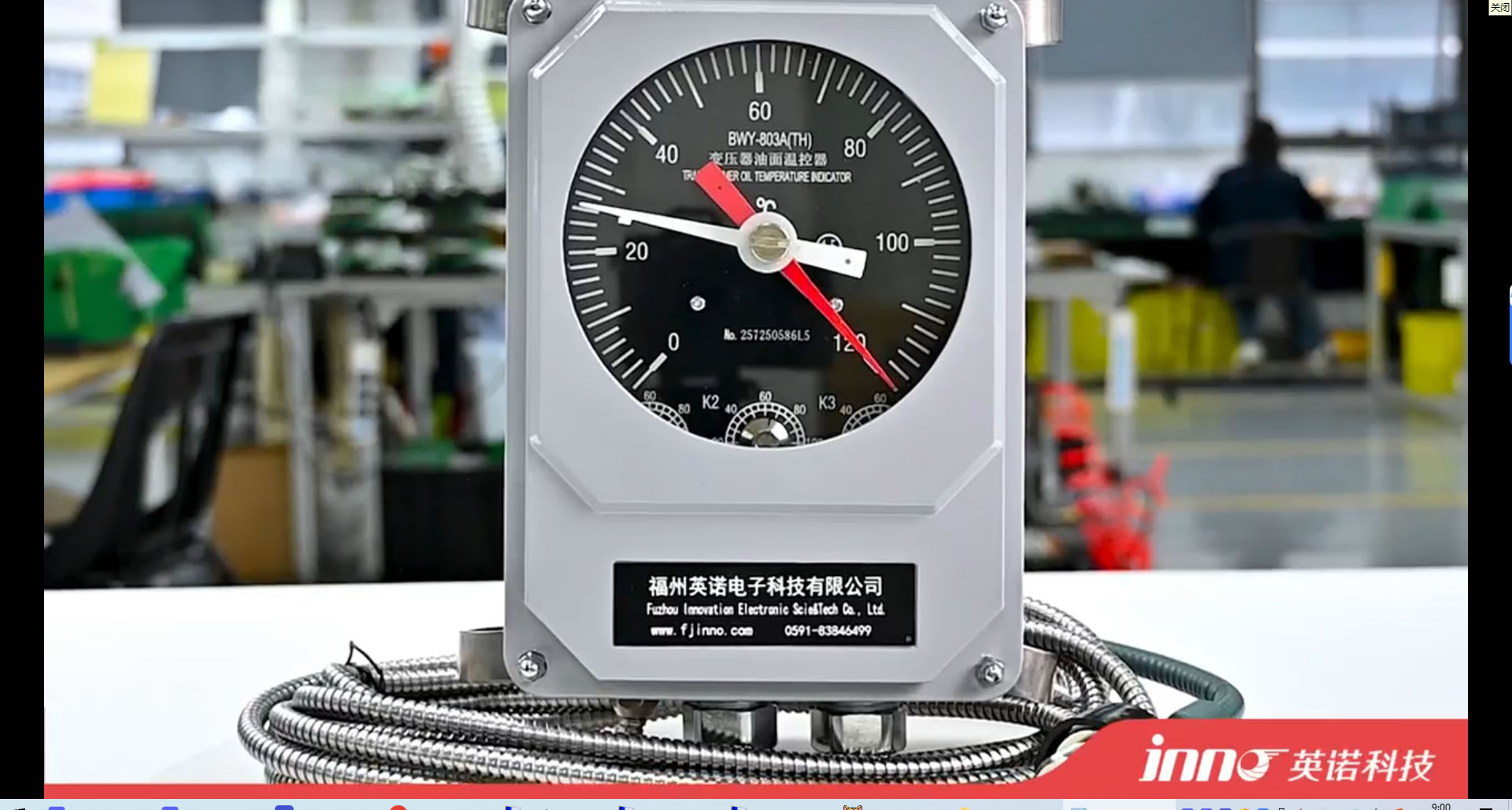
4.1 Princípio de funcionamento
Um indicador de temperatura do óleo (FEITO), also commonly referred to as an termômetro de óleo ou oil temperature gauge, measures the temperature of the insulating oil at or near the top of the transformer tank. The most common type uses a liquid-expansion (mercury or organic-filled) capillary system. A sensing bulb is inserted into a thermometer pocket welded on the transformer tank. As the oil temperature changes, the liquid in the bulb expands or contracts, driving a pointer on the dial gauge via the capillary tube.
4.2 Typical Parameters
Padrão FEITO devices offer a measurement range of 0–150°C, with an accuracy of approximately ±3–5°C. They typically include adjustable alarm and trip contacts (commonly set at 85°C and 95°C for top-oil temperature). The capillary length is usually available from 1 m to 20 eu. Response time is relatively slow, typically in the range of several minutes.
4.3 Limitações
O indicador de temperatura do óleo measures only the top-oil temperature, which does not directly represent the winding hot-spot temperature. The actual winding hot spot can be 20–40°C higher than the measured oil temperature. Mechanical components are subject to drift and aging over time, and the device cannot be easily integrated into modern digital monitoring systems without additional signal converters.
5. Traditional Method: Indicador de temperatura do enrolamento (WTI)
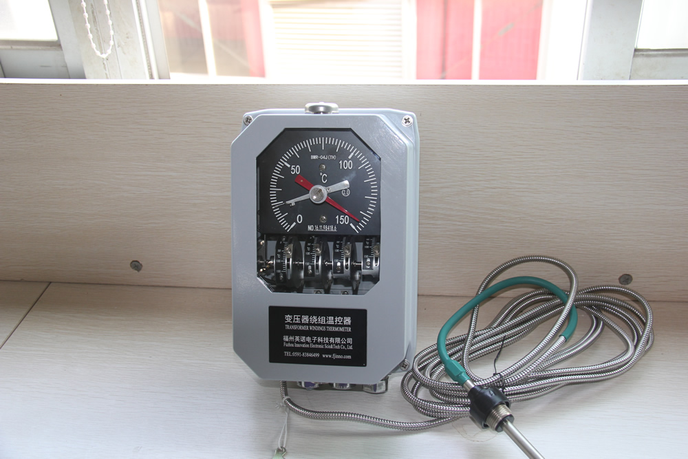
5.1 Princípio de funcionamento
UM indicador de temperatura do enrolamento (WTI) uses a thermal imaging (simulation) method to estimate the winding hot-spot temperature without directly measuring the winding conductor. A current transformer (TC) on the bushing provides a signal proportional to the load current. This signal feeds a small heating element coiled around the sensing bulb of a thermometer pocket. The combination of the ambient oil temperature and the thermal contribution from the heating resistor simulates the thermal gradient between the oil and the winding, producing an indirect estimate of the winding hot-spot temperature.
5.2 Calibration and Setup
During factory heat-run testing, o WTI is calibrated by adjusting the heating resistor current to match the measured winding-to-oil gradient at rated load. This calibration is specific to one loading condition. In the field, the relationship between load current and actual temperature gradient may deviate from the factory setting due to varying cooling conditions, oil aging, and non-linear thermal dynamics.
5.3 Typical Parameters
A standard indicador de temperatura do enrolamento provides a display range of 0–200°C with an accuracy of approximately ±3–5°C for the simulated value. It includes two to four adjustable contacts for fan start, pump start, alarme, e funções de viagem. Response time is moderate, typically 5–15 minutes due to the thermal inertia of the simulation element.
5.4 Limitações
Porque o WTI relies on an indirect thermal model rather than a direct measurement, its reading is an approximation. Under transient loading conditions, overload events, or when cooling system performance changes, the WTI may significantly deviate from the actual winding temperature. It is also vulnerable to calibration drift over the transformer’s service life.
6. Traditional Method: Thermocouple and RTD Sensors
6.1 Princípio de funcionamento
Sensores termopares (typically Type T or Type K) generate a voltage proportional to the temperature difference between the sensing junction and a reference junction. Detectores de temperatura com resistência de platina (IDT Pt100) measure temperature by detecting the change in electrical resistance of a platinum element. Both types can be embedded within the transformer winding during manufacturing to provide direct temperature readings of the conductor.
6.2 Typical Parameters
UM IDT Pt100 offers an accuracy of ±0.5–1.5°C across a range of −200°C to +600°C. Thermocouples provide accuracy of ±1–2.5°C. Response times vary from 1 para 10 seconds depending on the encapsulation. Both types require metallic lead wires routed from the winding interior out through the transformer structure.
6.3 Limitações
The primary drawback of embedded thermocouples and RTDs is that metallic lead wires introduce a conductive path into the high-voltage environment of the transformer winding. This creates insulation coordination challenges and increases the risk of dielectric failure. Electromagnetic interference from the transformer’s magnetic field can also affect signal integrity. Adicionalmente, these sensors can typically only be installed during manufacturing, making retrofit applications difficult.
7. Recomendado: Sistema de monitoramento de temperatura de fibra óptica fluorescente

7.1 Why Fluorescent Fiber Optic Technology Is Recommended
Among all available methods, o sistema de monitoramento de temperatura de fibra óptica fluorescente is the only technology that provides truly direct, medição em tempo real da temperatura do enrolamento do transformador com imunidade completa a interferência eletromagnética. Ao contrário do OTI e do WTI, que dependem de estimativa indireta, e diferentemente de termopares metálicos ou RTDs, que comprometem a integridade do isolamento, sensores fluorescentes de fibra óptica use fibras ópticas totalmente dielétricas que sejam inerentemente isolantes e introduzam risco elétrico zero no ambiente de enrolamento de alta tensão.
7.2 Princípio de detecção fluorescente GaAs
O sensor de temperatura de fibra óptica fluorescente opera com base nas características de decaimento de fluorescência dependentes da temperatura de um arseneto de gálio (GaAs) cristal semicondutor ligado à ponta de uma fibra óptica. Quando a luz pulsada do demodulador de fibra óptica excita o cristal GaAs, emite luz fluorescente cujo tempo de decaimento varia previsivelmente com a temperatura. O demodulador analisa a curva de decaimento para determinar a temperatura precisa no ponto de detecção. Este é um método de medição do tipo ponto, providing a discrete and accurate temperature value at each sensor location.
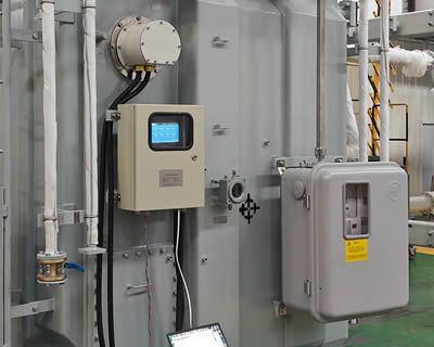
7.3 Composição do Sistema
Um completo sistema de monitoramento de temperatura de fibra óptica fluorescente consists of five key components:
Fiber Optic Temperature Demodulator (Transmissor)

O demodulador de temperatura de fibra óptica is the central processing unit of the system. Gera pulsos de luz de excitação, receives the returned fluorescent signal, and computes the temperature value. Um único demodulador suporta 1 para 64 canais de medição, making it suitable for monitoring multiple winding hot spots simultaneously. It provides an Interface de comunicação RS485 (Modbus RTU) for integration with DCS, SCADA, or transformer monitoring IEDs. All channel configurations and communication parameters are customizable per project requirements.
Fluorescent Fiber Optic Cable

O fibra óptica fluorescente cable transmits excitation and return light between the demodulator and the sensing probe. It is fully dielectric, oil-resistant, and designed for long-term immersion in transformer insulating oil. The cable length is available from 0 para 20 meters to accommodate various transformer sizes and routing requirements.
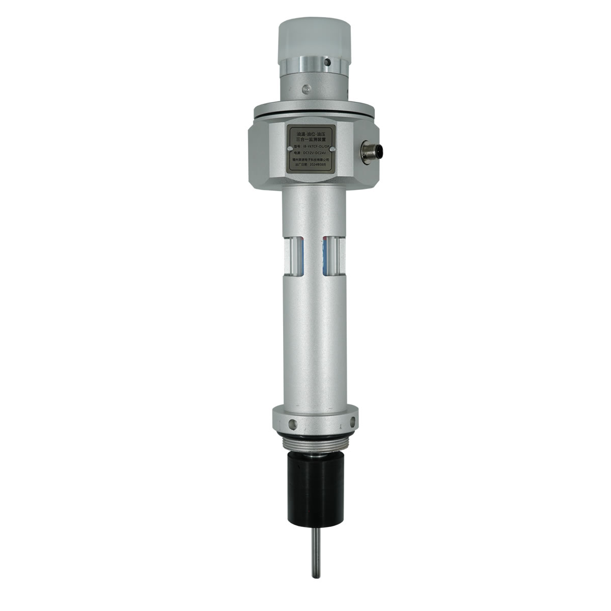
Sensing Probe
O fluorescent temperature sensing probe contains the GaAs crystal and is the point of actual temperature measurement. The probe features a compact diameter of 2–3 mm and can be customized for specific installation requirements. It withstands continuous operating voltages exceeding 100 kV, making it fully qualified for direct placement against winding conductors in high-voltage and ultra-high-voltage transformers.
Módulo de exibição
O módulo de exibição de temperatura provides local visual indication of all channel readings, status de alarme, e diagnóstico do sistema. It is typically panel-mounted on the transformer control cabinet.
Software de monitoramento
O software de monitoramento de temperatura runs on a connected PC or server and provides real-time trending, registro de dados históricos, gerenciamento de alarme, e geração de relatórios. It enables centralized remote monitoring of winding temperatures across multiple transformers.
7.4 Installation in Transformer Windings
O sonda de detecção de fibra óptica fluorescente is installed during transformer manufacturing by embedding it directly at the calculated hot-spot location within the winding structure, typically between insulated conductors at the top of the high-voltage or low-voltage winding. O cabo de fibra óptica is routed through the insulation structure and exits the transformer through a dedicated fiber optic feedthrough fitting on the tank wall. Because the entire sensor is non-metallic and non-conductive, it requires no special insulation coordination and introduces no risk to the transformer’s dielectric performance.
8. Technical Comparison of All Four Methods
A tabela a seguir fornece uma comparação abrangente lado a lado de todos os quatro métodos de monitoramento de temperatura dos enrolamentos do transformador discutidos neste artigo..
| Parâmetro | FEITO (Indicador de temperatura do óleo) | WTI (Indicador de temperatura do enrolamento) | Termopar / IDT | Fibra Óptica Fluorescente (GaAs) |
|---|---|---|---|---|
| Tipo de medição | Indireto (somente óleo) | Indireto (thermal simulation) | Direto (integrado) | Direto (integrado) |
| Precisão | ±3–5°C | ±3–5°C | ±0,5–2,5°C | ±0,5–1°C |
| Faixa de medição | 0–150ºC | 0–200ºC | −200 a +600°C | −40 a +260°C |
| Tempo de resposta | Vários minutos | 5–15 minutos | 1–10 segundos | <1 segundo |
| Imunidade EMI | Moderado | Moderado | Pobre | Completo (all-dielectric) |
| Tensão suportável | N / D (external) | N / D (external) | Limitado | >100 kV |
| Diâmetro da Sonda | Tipo de lâmpada | Tipo de lâmpada | 3–6mm | 2–3mm (personalizável) |
| Material do sensor | Metálico | Metálico | Metálico | All-dielectric (isolante) |
| Comprimento do cabo/fibra | 1–20m | 1–20m | Limited by signal loss | 0–20m |
| Capacidade do canal | Solteiro | Solteiro | Multiponto (wired) | 1–64 canais por demodulador |
| Comunicação | Somente contatos (analog) | Somente contatos (analog) | Analog signal / 4–20 mA | RS485 (Modbus RTU), personalizável |
| Vida útil | 10–15 anos | 10–15 anos | 10–20 anos | >25 anos |
| Retrofit Capability | Fácil | Fácil | Difficult | Instalação de fábrica recomendada |
| Custo relativo | Baixo | Baixo-Médio | Médio | Médio-Alto |
Como mostrado na tabela, o sistema de monitoramento de temperatura de fibra óptica fluorescente oferece a melhor combinação de precisão de medição, velocidade de resposta, imunidade eletromagnética, segurança dielétrica, e longa vida útil — tornando-o a escolha certa para transformadores de potência críticos, onde dados confiáveis de temperatura do enrolamento são essenciais.
9. Casos de aplicação globais

Sistemas de monitoramento de temperatura de enrolamentos de fibra óptica fluorescentes have been deployed in a wide range of transformer applications worldwide. The following are representative examples demonstrating proven performance across different voltage classes and operating environments.
9.1 High-Voltage Power Transformers (110 kV – 220 kV)
Multiple utility-class 110 kV and 220 kV power transformers in large-scale substation projects across Asia, o Médio Oriente, and South America have been equipped with sensores fluorescentes de fibra óptica embedded at the calculated hot-spot locations. These installations enabled real-time winding temperature visibility and dynamic loading optimization, replacing older WTI-based thermal estimates.
9.2 Ultra-High-Voltage (UHV) Transmission Transformers
In ultra-high-voltage transmission projects operating at 500 kV e acima, the all-dielectric nature of the sonda de detecção de fibra óptica fluorescente is a critical advantage. These transformers demand absolute insulation integrity, and conventional metallic sensors are not acceptable. Fluorescent fiber optic systems have been successfully installed in multiple UHV transformer units, providing continuous hot-spot monitoring under extreme voltage stress.
9.3 Industrial and Traction Transformers
In industrial applications such as arc furnace transformers and railway traction transformers, highly variable and cyclic loading profiles make accurate winding temperature monitoring essential. Sistemas de fibra óptica fluorescente provide the fast response time (<1 segundo) needed to track rapid thermal transients, enabling precise thermal protection under dynamic operating conditions.
9.4 Renewable Energy and Offshore Transformers
Transformers serving wind farms and offshore platforms operate in harsh and remote environments where maintenance access is limited. Monitoramento de temperatura por fibra óptica with remote data access via RS485 and SCADA integration allows operators to manage thermal performance without physical site visits, significantly reducing operational risk and maintenance cost.
10. Winding Temperature Protection and Control Logic

Winding temperature measurements are used to drive protective actions and cooling control. In a typical implementation, the monitoring system triggers the following responses based on configurable temperature thresholds.
10.1 Cooling System Activation
When the winding temperature reaches a first-stage threshold (commonly 85–95°C), the monitoring system sends a command to start additional cooling fans or oil pumps. This activates supplementary cooling stages (ONAF or ODAF) to increase heat dissipation capacity.
10.2 Alarme
A second-stage threshold (commonly 105–110°C) triggers a high-temperature alarm, que é anunciado localmente no painel de controle do transformador e transmitido remotamente ao sistema SCADA para ação do operador.
10.3 Viagem
Se a temperatura continuar a subir e atingir um limite crítico (geralmente 120–130°C), um comando de disparo é emitido para desenergizar o transformador e evitar danos irreversíveis ao isolamento. Este sinal faz interface com o relé de proteção do transformador através de contatos secos ou comunicação digital.
10.4 Integração SCADA e DCS
O demodulador de temperatura de fibra óptica fluorescente transmite dados de temperatura em tempo real via RS485 (Modbus RTU) ao sistema SCADA da subestação ou DCS da planta. Isso permite o monitoramento centralizado, tendências históricas, e gerenciamento térmico coordenado em vários transformadores.
11. Get a Customized Solution
Cada aplicação de transformador possui requisitos exclusivos para contagem de canais, roteamento de cabos de fibra, configuração de exibição, e integração de sistemas. Nossa equipe de engenharia em FJINNO provides tailored soluções de monitoramento de temperatura de fibra óptica fluorescente for transformer manufacturers, utilitários, and industrial operators worldwide.
Whether you need a standard 4-channel system for a distribution transformer or a 64-channel configuration for a large power transformer bank, we deliver fully customized hardware and software packages with complete technical support.
Contate-nos hoje to discuss your project requirements, request a quotation, or schedule a technical consultation. Visit www.fjinno.net para mais informações.
12. Perguntas frequentes (Perguntas frequentes)
1º trimestre: What is the difference between oil temperature and winding temperature in a transformer?
Oil temperature represents the temperature of the insulating oil, typically measured at the top of the tank. Winding temperature is the actual temperature of the copper or aluminum conductor in the winding, which is always higher than the oil temperature due to the thermal gradient. The hot-spot winding temperature can be 20–40°C above the top-oil temperature under full load.
2º trimestre: Why is a WTI not considered a direct measurement method?
A winding temperature indicator uses a thermal simulation approach. It estimates winding temperature by adding a current-dependent thermal contribution to the measured oil temperature. It does not have a sensor placed on the actual winding conductor, so it cannot capture the true hot-spot temperature under all operating conditions.
3º trimestre: How does a fluorescent fiber optic sensor withstand high voltage inside a transformer?
The fluorescent fiber optic sensor is made entirely of non-metallic, dielectric materials — glass fiber and a GaAs crystal tip. Não conduz eletricidade e, portanto, não introduz nenhum caminho condutor na estrutura de isolamento. Isso permite que ele opere com segurança em níveis de tensão superiores 100 kV.
4º trimestre: Os sensores fluorescentes de fibra óptica podem ser adaptados em um transformador existente?
Sensores fluorescentes de fibra óptica são instalados de forma mais eficaz durante o processo de fabricação do transformador, quando eles podem ser posicionados com precisão no local calculado do ponto quente dentro do enrolamento. Retrofit em um selado, transformador cheio de óleo não é prático sem remover a parte ativa. Para transformadores existentes, WTI ou métodos de monitoramento externo são normalmente usados.
Q5: Quantos pontos de detecção um demodulador pode controlar?
Um único demodulador de temperatura de fibra óptica fluorescente suporta 1 para 64 canais. Cada canal se conecta a uma sonda de detecção para medição de temperatura tipo ponto independente. The channel count is configurable based on the specific project needs.
Q6: What communication protocol does the system use?
The standard communication interface is RS485 using the Modbus RTU protocol, which is widely compatible with substation SCADA systems, Plataformas DCS, and intelligent electronic devices (IEDs). Other communication options can be customized upon request.
Q7: What is the expected service life of a fluorescent fiber optic temperature sensor?
The fluorescent fiber optic sensing probe and fiber cable are designed for a service life exceeding 25 anos, which matches or exceeds the typical design life of a power transformer. The all-glass construction and sealed GaAs crystal are resistant to degradation in transformer oil environments.
P8: What international standards apply to transformer winding temperature limits?
The primary standards are IEC 60076-2 (limites de aumento de temperatura), CEI 60076-7 (guia de carregamento), IEEE Std C57.12.00 (general requirements), and IEEE Std C57.91 (carregamento e modelagem térmica). Estas normas definem temperaturas máximas permitidas de elevação do enrolamento e limites de pontos quentes para diversas condições de carga..
Q9: O sensor de fibra óptica fluorescente é afetado por interferência eletromagnética?
Não. Como o sensor é totalmente não metálico e o princípio de medição é baseado em sinais ópticos e não em sinais elétricos, é completamente imune à interferência eletromagnética do campo magnético do transformador, comutação de transientes, ou equipamento de alta tensão próximo.
Q10: Como determino o número correto de sensores necessários para meu transformador?
O número de pontos de detecção depende do projeto do transformador, classe de tensão, tipo de resfriamento, e o número de enrolamentos a serem monitorados. Tipicamente, sensores são colocados nos locais calculados de pontos quentes de cada enrolamento principal (Alta tensão, LV, e terciário, se aplicável). Our engineering team can assist with sensor placement planning based on the thermal design data of your specific transformer. Contate-nos em www.fjinno.net for technical support.
13. Isenção de responsabilidade
The information provided in this article is intended for general educational and reference purposes only. While every effort has been made to ensure the accuracy and reliability of the content at the time of publication, FJINNO makes no warranties or representations, expresso ou implícito, em relação à completude, precisão, or suitability of the information for any specific application. Transformer design, instalação, and monitoring practices must comply with applicable local and international standards, regulations, and engineering best practices. Readers are advised to consult qualified engineers and refer to the latest editions of relevant standards before making any design or purchasing decisions. A FJINNO não será responsável por qualquer, indireto, ou danos consequentes decorrentes do uso ou confiança nas informações apresentadas neste artigo. Para orientação técnica específica do projeto, entre em contato com nossa equipe de engenharia em www.fjinno.net.

Sensor de temperatura de fibra óptica, Sistema de monitoramento inteligente, Fabricante distribuído de fibra óptica na China
|
 |
 |