 Sensores de temperatura de fibra óptica INNO ,sistemas de monitoramento de temperatura.
- Monitoramento de temperatura de conexão de cabo impede mais 85% de falhas de superaquecimento, já que as juntas de cabos representam mais de 40% de falhas no sistema de distribuição causadas por resistência de contato
- Sensores de temperatura de fibra óptica fornecer isolamento elétrico de 100kV, resolvendo o desafio fundamental da medição de temperatura em ambientes de alta tensão
- Sistema de monitoramento único suporta 4-16 pontos de medição para cobertura abrangente de barramentos, conexões de cabos de entrada e saída, e pontos de contato dinâmicos
- A precisão de ±0,5 °C com tempo de resposta de 0,5 segundos captura sinais de alerta precoce de aumento anormal de temperatura nas juntas dos cabos
- A classificação de proteção IP67 garante operação confiável em ambientes agressivos, incluindo armários de distribuição, cofres de cabos, e túneis subterrâneos
- 20-o design livre de manutenção por um ano elimina os requisitos de calibração periódica e reduz os custos operacionais de longo prazo
Índice
1. Why Are Cable Connections the Most Vulnerable Points for Overheating in Distribution Systems?
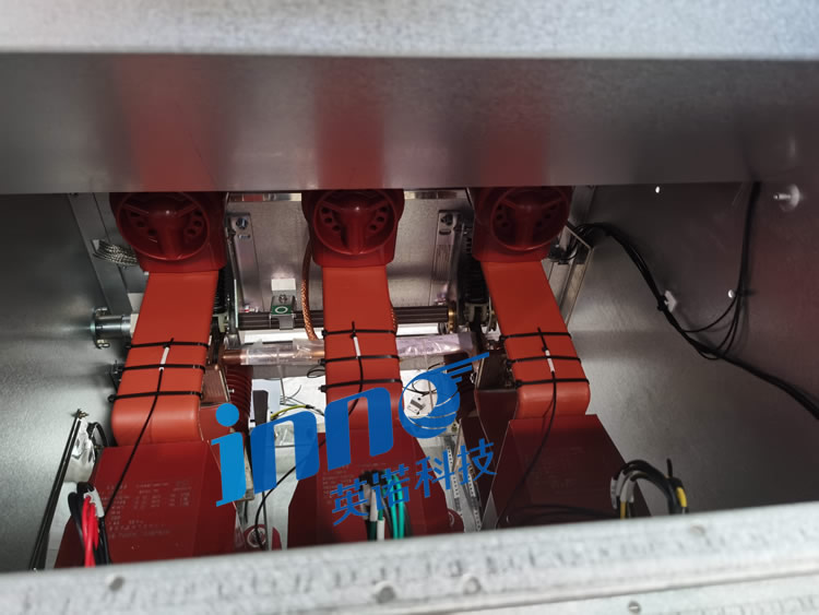
Cable connections represent the weakest thermal links in electrical distribution networks, contabilizando mais 40% of system failures attributed to excessive heating. Unlike continuous conductors with uniform cross-sections, connection points introduce contact resistance that generates localized heat under load current.
1.1 Physical Causes of Increased Contact Resistance
Three primary mechanisms drive contact resistance degradation in conexões de cabo: surface oxidation creates insulating layers on conductor interfaces, mechanical loosening from thermal cycling reduces contact pressure, and contamination from dust or moisture forms resistive films. Each mechanism incrementally increases resistance, compounding heat generation through I²R losses.
1.2 Statistical Analysis of Cable Connection Failures and Economic Losses
Industry data reveals that cable connection temperature monitoring can prevent 85% of overheating-related failures. Unplanned outages from cable joint failures cost industrial facilities an average of $50,000-$500,000 per incident when considering lost production, danos ao equipamento, and emergency repair expenses. Proactive temperature monitoring delivers immediate return on investment through failure prevention.
2. What Fundamental Limitations Do Traditional Cable Connection Temperature Monitoring Technologies Have?
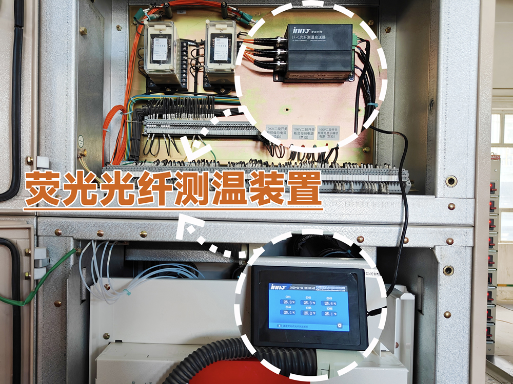
Conventional temperature measurement approaches face insurmountable obstacles when applied to high voltage cable connections in enclosed switchgear environments.
2.1 Infrared Thermography Visual Obstruction and Accuracy Issues
Infrared cameras require direct line-of-sight to measurement targets, making them ineffective for enclosed switchgear where cable connections are surrounded by grounded metal compartments. Viewing windows introduce measurement errors from glass transmission characteristics, while periodic manual inspections miss transient overheating events between inspection intervals. Environmental factors including ambient temperature, umidade, and surface emissivity variations further compromise infrared measurement accuracy.
2.2 Thermocouple Insulation Risks in High Voltage Cabinets
Metal thermocouple wires create conductive paths between high voltage conductors and grounded monitoring equipment, requiring extensive insulation that increases installation complexity and introduces failure points. Electromagnetic interference from switching transients and load currents induces noise in thermocouple signals, corrupting measurements. The fundamental incompatibility between metallic sensors and high voltage environments limits thermocouple applications to low voltage installations.
3. Como fazer Fiber Optic Temperature Sensors Achieve Safe Isolation Measurement for Cable Connections?
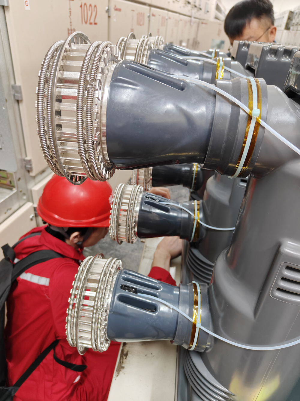
Sensores de temperatura de fibra óptica solve the electrical isolation challenge through all-dielectric construction containing zero conductive materials.
3.1 All-Dielectric Structure Insulation Principle
The complete signal path from sensing point to monitoring equipment consists of pure glass optical fiber, ceramic or polymer probe housing, and rare-earth fluorescent sensing elements. This entirely non-conductive design provides inherent electrical isolation without requiring additional insulating barriers. The sensor functions as an infinite impedance to electrical currents while maintaining full temperature measurement capability.
3.2 100kV Voltage Withstand Rating Technical Assurance
Padrão sensores de temperatura de fibra óptica para monitoramento de temperatura do painel applications undergo high voltage testing to verify withstand capability exceeding 100kV. This voltage rating allows direct installation on energized conductors at any distribution voltage level without creating safety hazards or measurement interference. The electrical isolation eliminates ground loops, common-mode voltage effects, and electromagnetic interference that plague conventional sensor technologies.
4. What Are the Temperature Measurement Requirement Differences Between Incoming and Outgoing Cable Connections?
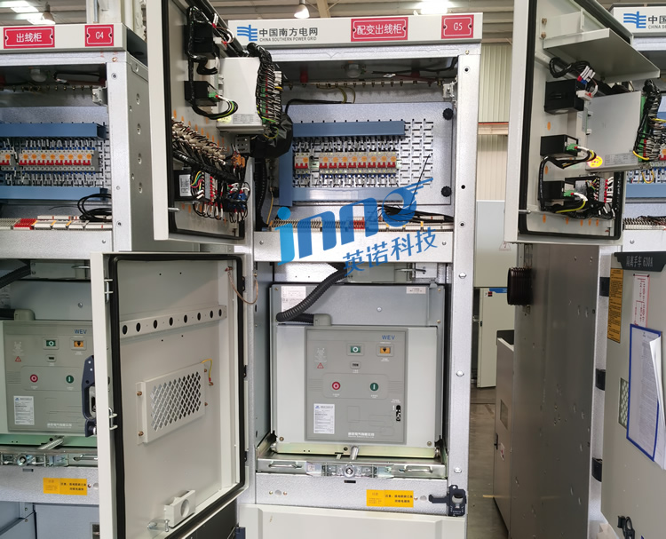
4.1 Incoming Side High-Current Connection Hot Spot Distribution
Incoming cable connections typically handle the full load current for downstream distribution equipment, creating concentrated thermal loads at utility service entrance points. These connections experience continuous high current flow with minimal variation, allowing steady-state thermal analysis. The primary monitoring objective focuses on detecting gradual resistance increase from oxidation or mechanical loosening before temperatures reach damaging levels.
4.2 Outgoing Side Load Fluctuation Temperature Characteristics
Outgoing cable connections serving individual loads exhibit dynamic thermal behavior correlated with load cycles. Temperature measurements must account for normal variations during load changes versus abnormal temperature rise indicating connection degradation. Multi-point monitoring distinguishes between expected thermal response to load current and developing connection problems requiring maintenance intervention.
5. What Core Components Comprise a Complete Switchgear Temperature Monitoring System Arquitetura?

5.1 System Integration of Fiber Probes, Transmissores, and Display Instruments
Um abrangente cable connection online monitoring system integrates multiple functional elements: sondas de temperatura de fibra óptica installed at measurement points, optical fiber transmission cables routing signals to monitoring equipment, fluorescent fiber temperature transmitters providing optical excitation and signal processing, and LCD display instruments presenting real-time data with alarm management.
5.2 Typical Switchgear Temperature Measurement System Configuration Diagram Analysis
The installation schematic reveals strategic sensor placement throughout switchgear compartments. Yellow-marked positions ① indicate busbar monitoring points at main copper bar connections. Orange positions ⑥ show incoming and outgoing cable temperature measurement locations where power cables connect to switchgear terminals. Red position ⑤ identifies dynamic contact point monitoring on circuit breaker switching mechanisms. A posição verde ③ localiza o transmissor de temperatura de fibra óptica que abriga os componentes eletrônicos de medição multicanal. A posição azul ② exibe o instrumento de monitoramento LCD que fornece interface do operador. A posição roxa ④ mostra o flange do adaptador de fibra óptica gerenciando múltiplas conexões de sonda à unidade transmissora.
6. Why Must High Voltage Cable Connections Use Fiber Optic Temperature Measurement Solutions?
6.1 Requisitos de distância de isolamento para conexões de cabos de 10kV/35kV
Conexões de cabos de alta tensão em painéis de 10kV e 35kV exigem folgas mínimas de isolamento de ar de 160 mm e 310 mm, respectivamente, de acordo com a IEC 62271-200 padrões. Sensores convencionais com fiação condutiva violam essas folgas ou exigem espaçadores isolantes volumosos que complicam a instalação. A natureza totalmente dielétrica do sensores de fibra óptica elimina preocupações com distância de isolamento, permitindo montagem direta em condutores energizados.
6.2 Safety Hazards of Traditional Metallic Sensors
Metal sensor components introduced into high voltage environments create multiple hazards including partial discharge inception points, fault current paths during equipment failures, and electromagnetic coupling that induces dangerous voltages on grounded monitoring equipment. These safety concerns prohibit use of conventional sensors in high voltage applications where medição de temperatura de fibra óptica provides the only viable solution.
7. How Do Distribution Cabinet Temperature Sensors Achieve Multi-Point Simultaneous Monitoring?
7.1 4-16 Channel Fluorescent Fiber Optic Temperature Measurement System Configuration
Multi-point temperature monitoring systems connect 4, 8, 12, ou 16 independente sondas de temperatura de fibra óptica to a single transmitter unit through multi-channel optical switching or parallel measurement channels. Each probe operates on a dedicated optical pathway, enabling simultaneous temperature acquisition from all measurement points without signal interference between channels. The centralized architecture reduces equipment costs compared to deploying separate single-channel systems for each measurement location.
7.2 Multi-Point Temperature Data Centralized Acquisition
O termometria de fibra óptica fluorescente transmitter sequentially or simultaneously excites all connected probes, measures their fluorescence decay characteristics, and converts optical signals to temperature values. Digital signal processing algorithms apply factory calibration data and environmental compensation to deliver accurate temperature readings for each channel. The system presents all measurement points through unified display interfaces and communication protocols.
8. Why Is Busbar Connection Temperature Monitoring a Critical Protection Focus in Distribution Cabinets?
8.1 Stress Concentration Phenomena at Copper Bar Connection Points
Busbar systems use bolted mechanical connections to join copper bar sections and create branch connections. These joints concentrate mechanical stress at contact interfaces, making them susceptible to loosening from thermal expansion cycling and mechanical vibration. Even minor reductions in bolt torque significantly increase contact resistance and heat generation.
8.2 Oxidation and Corrosion Mechanisms at Busbar Overlap Surfaces
Copper busbar surfaces oxidize when exposed to air, forming copper oxide layers that exhibit higher electrical resistance than pure copper. Bolted connections trap oxygen and moisture at interfaces, accelerating oxidation and creating progressive resistance increase. Monitoramento de temperatura detects the thermal signature of this electrochemical degradation before it causes failures, enabling preventive maintenance to restore connection quality.
9. How to Implement Online Temperature Monitoring for Breaker Dynamic and Static Contact Points?
9.1 Vacuum Circuit Breaker Contact Wear Characteristics
Vacuum circuit breakers experience contact erosion from each switching operation, gradually reducing contact surface area and increasing contact resistance. The enclosed vacuum bottle prevents visual inspection of contact condition, making temperature monitoring the primary method for detecting excessive wear requiring maintenance. Sensores de fibra óptica mounted on breaker terminals track contact temperature rise as wear progresses.
9.2 SF6 Circuit Breaker Contact Resistance Monitoring
SF6 circuit breakers use high-pressure gas to extinguish arcs during interruption. Contact surfaces can develop carbon deposits from arcing or experience mechanical alignment issues that increase resistance. Temperature measurements at breaker terminals reveal contact degradation through abnormal heating under load current, supporting condition-based maintenance programs that optimize contact servicing intervals.
10. What Are the Measurement Point Layout Principles for Cable Terminal Temperature Monitoring Systems?
10.1 Temperature Sensitivity of Stress Cone Areas
Cable terminal temperature monitoring focuses on stress relief cones where high voltage cable insulation transitions to air insulation. These regions experience concentrated electrical stress that can cause partial discharge and heating if improperly installed. Temperature sensors detect thermal anomalies indicating insulation problems before they progress to complete failures.
10.2 Priority Monitoring of Ground Wire Connection Points
Cable terminal ground connections carry fault currents during short circuit events and must maintain low resistance for effective protection system operation. Corroded or loose ground connections develop high resistance that creates dangerous voltage rise on cable sheaths during faults. Regular temperature monitoring verifies ground connection integrity as part of comprehensive cable connection temperature monitoring programs.
11. How to Scientifically Position Sensors in Incoming and Outgoing Cable Temperature Measurement Systems?
11.1 Balanced Monitoring of Three-Phase Cable Connections
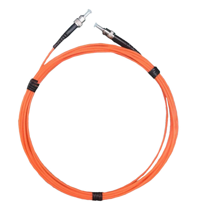
Incoming and outgoing cable temperature measurement systems install sensors on all three phase conductors to detect asymmetric heating patterns. Properly balanced three-phase loads produce similar temperatures on all phases, while single-phase overloads or phase-specific connection problems create temperature differences between phases. Comparative analysis of three-phase temperatures enables rapid fault identification and classification.
11.2 Temperature Identification of Single-Phase Ground Faults
High resistance ground faults may not trip overcurrent protection but cause localized heating at fault points. Multi-point temperature monitoring detects abnormal temperature rise on affected phases, providing early warning of developing insulation failures. The measurement data supports predictive maintenance by identifying cables requiring detailed inspection before catastrophic failures occur.
12. What Functions Does the LCD Display Instrument Provide in Cable Connection Online Monitoring Systems?
12.1 Multi-Channel Real-Time Temperature Curve Display
O LCD display instrument simultaneously presents current temperature readings for all monitored points with graphical trend displays showing temperature evolution over time. Color-coded indicators highlight normal, aviso, and alarm conditions for each measurement channel. Operators monitor the complete thermal profile of switchgear from a single interface, quickly identifying developing problems requiring attention.
12.2 Historical Data Query and Trend Analysis
Integrated data logging captures temperature measurements at configurable intervals, creating permanent records for analysis and documentation. Historical data review reveals gradual temperature trends indicating progressive connection degradation, supports troubleshooting of intermittent problems, and provides evidence for regulatory compliance and quality management systems.
13. What Is the Working Principle of Medição de temperatura de fibra óptica fluorescente Tecnologia?

13.1 Temperature Response Characteristics of Rare-Earth Fluorescent Materials
Termometria de fibra óptica fluorescente employs rare-earth phosphor compounds exhibiting temperature-dependent fluorescence decay. The transmitter sends light pulses through optical fiber to excite fluorescent material at the probe tip. Excited electrons in the phosphor material absorb energy and subsequently emit fluorescence at a different wavelength, with decay time that varies predictably and repeatably with temperature.
13.2 Accuracy Advantages of Fluorescence Lifetime Measurement
Precision timing electronics measure fluorescence decay duration with nanosecond resolution, converting this optical time constant into accurate temperature readings. The measurement principle depends solely on fluorescence kinetics, providing immunity to optical power variations, perdas de flexão de fibra, and connector condition that affect intensity-based measurement techniques. This approach delivers Precisão de ±0,5°C with exceptional long-term stability.
14. What Practical Value Does ±0.5°C Measurement Accuracy Offer for Cable Connection Fault Prevention?

14.1 Early Detection Capability for Minor Temperature Rise
O Precisão de ±0,5°C specification enables detection of temperature increases as small as 2-3°C above normal operating levels, providing early warning before connections reach dangerous temperatures. Cable joints typically exhibit gradual temperature rise over weeks or months as contact resistance increases. High accuracy measurement captures this progression in initial stages when simple maintenance can restore normal conditions.
14.2 Comparative Analysis with Environmental Temperature Compensation
Cable connection temperature monitoring systems measure both connection temperatures and ambient temperature within switchgear enclosures. Subtracting ambient temperature from connection readings yields temperature rise values that directly indicate connection condition independent of environmental variations. Accurate ambient measurement allows precise calculation of these temperature differentials for reliable fault detection.
15. How Do Temperature Measurement Solutions Differ Between Cable Intermediate Joints and Terminal Joints?
15.1 Características de temperatura das conexões da camada de blindagem de junta intermediária
Juntas intermediárias de cabos em sistemas de distribuição subterrânea unem seções de cabos em bueiros ou cofres. Estas juntas devem manter a continuidade elétrica das camadas metálicas de blindagem, ao mesmo tempo que fornecem isolamento de alta tensão.. Os pontos de conexão da blindagem podem desenvolver alta resistência à corrosão em ambientes úmidos, criando aquecimento localizado. Sensores de temperatura de fibra óptica com classificação à prova d'água IP68 monitore essas conexões submersas de maneira confiável por anos sem degradação.
15.2 Distribuição de pontos quentes em áreas de cone de tensão terminal
Cable terminal temperature a medição concentra-se na região do cone de tensão onde termina o isolamento do cabo. Técnicas de instalação inadequadas ou defeitos de isolamento concentram o estresse elétrico, causando descarga parcial e aquecimento. O monitoramento de temperatura detecta essas anomalias térmicas, supporting quality verification of terminal installations and ongoing condition assessment during service.
16. What Are Typical Application Cases of Cable Connection Temperature Monitoring in 10kV Switchgear?
16.1 Ring Main Unit Incoming and Outgoing Line Temperature Measurement Configuration
10kV ring main units serving urban distribution networks use compact switchgear with limited space for temperature monitoring equipment. Sensores de temperatura de fibra óptica with 600μm diameter probes fit within confined compartments, monitoring cable connections at loop-in, loop-out, and transformer feeder positions. The small sensor size and flexible optical fiber enable installation without switchgear modifications.
16.2 Comprehensive Monitoring for Fixed Switchgear
Industrial facility 10kV switchgear installations benefit from complete multi-point temperature monitoring covering busbar connections, circuit breaker terminals, conexões de cabo, and transformer terminations. Sistemas com 12-16 measurement channels provide comprehensive thermal surveillance, detecting problems anywhere in the electrical distribution path from utility service entrance through load feeders.
17. How to Implement Cable Connection Temperature Online Monitoring in 35kV High Voltage Switchgear?
17.1 Insulation Distance Limitations in High Voltage Cabinets
35kV monitoramento de temperatura do painel must maintain 310mm minimum phase-to-ground clearances and 370mm phase-to-phase spacings. A construção totalmente dielétrica de sensores de fibra óptica allows installation directly on energized conductors without compromising these safety distances. Flexible optical fiber routes through existing cable glands and bushing penetrations without requiring additional insulated feedthroughs.
17.2 Secure Pathway Design for Fiber Optic Routing
Optical fiber routing within high voltage switchgear follows established cable pathways, maintaining separation from live parts and avoiding sharp bends that could damage fiber. Protective conduit shields fiber from mechanical damage during maintenance activities. Proper fiber management ensures reliable signal transmission while preserving switchgear safety ratings and simplifying future maintenance access.
18. How to Achieve Remote Temperature Monitoring in Underground Cable Vaults and Tunnels?
18.1 IP68 Waterproof Probe Encapsulation for Moisture Protection
Underground cable installations experience high humidity and periodic flooding that destroys conventional sensors. Sondas de temperatura de fibra óptica with IP68 waterproof rating withstand continuous submersion while maintaining measurement accuracy. Hermetically sealed probe construction prevents moisture ingress that would compromise optical components, ensuring decades of reliable operation in harsh underground environments.
18.2 Signal Assurance for Long-Distance Fiber Optic Transmission
Fluorescent fiber systems support optical fiber runs exceeding 500 meters from measurement points to monitoring equipment without signal degradation or repeaters. This capability enables centralized monitoring of multiple cable vaults from a single control room location. The low optical loss of standard communication-grade fiber ensures reliable transmission over extended distances encountered in utility cable networks.
19. How to Set Scientific Alarm Thresholds for Cable Connection Temperature Monitoring Systems?
19.1 CEI 60439 Standard Temperature Rise Limits
International standards specify maximum allowable temperature rise for electrical connections based on conductor material and insulation class. Bare copper connections typically limit temperature rise to 65°C above ambient, while insulated connections allow 70-80°C rise depending on insulation rating. Monitoramento de temperatura de conexão de cabo alarm thresholds align with these standards, providing warning before temperatures exceed equipment ratings.
19.2 Three-Level Alarm Strategy: Pre-Warning, Alarme, and Trip
Sophisticated monitoring systems implement multiple alarm levels supporting progressive response to developing problems. Pre-warning alarms at 80% of maximum allowable temperature alert operators to schedule maintenance during planned outages. High-level alarms at 90% threshold trigger immediate investigation and load reduction. Critical alarms at 100% rating can initiate automatic circuit breaker tripping to prevent equipment damage from extreme overheating.
20. How Do Multi-Point Temperature Monitoring Systems Interface with Distribution Automation SCADA?
20.1 Modbus RTU/TCP Communication Protocol Configuration
Transmissores de temperatura de fibra óptica provide Modbus RTU serial communication and Modbus TCP Ethernet networking for integration with supervisory control and data acquisition systems. Standard protocol implementation allows SCADA systems to poll temperature data, status de alarme, and system diagnostics from monitoring equipment. Configuration tools map measurement channels to SCADA point addresses matching system architecture requirements.
20.2 CEI 61850 Intelligent Substation Communication Standards
Modern digital substations use IEC 61850 protocols for device communication and integration. Avançado sistemas de monitoramento de temperatura support IEC 61850 client/server models with Generic Object Oriented Substation Event (GOOSE) messaging for high-speed alarm propagation. This standards-based approach enables seamless integration with digital substation automation systems.
21. How to Implement Protection-Grade Temperature Measurement for Outdoor Cable Junction Box Connections?
21.1 IP67 Outdoor Protection Requirements
Outdoor cable junction boxes experience rain, neve, gelo, and direct sunlight requiring sensores de temperatura de fibra óptica with IP67 minimum protection rating. Sealed probe housings prevent water and dust ingress while maintaining thermal contact with monitored conductors. UV-resistant materials prevent degradation from sunlight exposure during decades of outdoor service.
21.2 Wide Temperature Range -40°C to +125°C Adaptability
Outdoor installations encounter extreme ambient temperatures from arctic winters to desert summers. Fiber temperature sensors specified for -40°C to +125°C operation maintain accuracy and reliability across this range without recalibration. The wide operating window ensures measurement capability in all climates and seasons without seasonal adjustments.
22. Why Are Copper-Aluminum Transition Cable Connections Priority Objects for Temperature Monitoring?
22.1 Electrochemical Corrosion Causing Increased Contact Resistance
Copper-aluminum transition connections join dissimilar metals with different electrochemical potentials. Moisture exposure creates galvanic corrosion at the interface, progressively increasing contact resistance and heat generation. This electrochemical mechanism accelerates degradation compared to copper-to-copper or aluminum-to-aluminum connections, making temperature monitoring especially valuable for bimetallic joints.
22.2 Temperature Rise Rate Characteristics of Copper-Aluminum Connections
Bimetallic connections exhibit faster temperature rise rates when experiencing degradation due to oxide formation and corrosion product buildup. Monitoramento de temperatura de conexão de cabo detects these accelerated thermal changes, providing shorter warning times before failure compared to homogeneous metal connections. Frequent measurement updates and sensitive alarm thresholds optimize early detection for these high-risk connection types.
23. How to Distinguish Between Connection Problems and Overload When Cable Connection Temperature Abnormalities Occur?
23.1 Three-Phase Temperature Comparison Analysis Methods
Overload conditions affect all three phases equally, producing similar temperature rises on all conductors. Connection problems typically affect single phases, creating asymmetric heating patterns. Comparing temperatures between phases identifies whether heating stems from excessive load current or localized connection resistance. Temperature differences exceeding 10°C between phases indicate connection problems requiring maintenance regardless of load levels.
23.2 Correlation Between Load Current and Temperature Rise
Integrating temperature monitoring with current measurement establishes the relationship between load and temperature for each connection. Properly functioning connections exhibit predictable temperature rise proportional to current squared (Aquecimento I²R). Connections developing problems show temperature rise exceeding expected values for measured current levels. This correlation analysis separates normal thermal response from abnormal resistance-driven heating.
24. How to Verify Long-Term Reliability of Cable Connection Temperature Measurement Systems?
24.1 Standard Procedures for System Commissioning Testing
A instalação profissional inclui testes de comissionamento abrangentes que verificam todos os canais de medição, interfaces de comunicação, e funções de alarme. O teste confirma o contato térmico adequado do sensor, qualidade do sinal óptico, precisão de medição, e integração de sistemas com equipamentos de controle. A documentação dos resultados de comissionamento estabelece o desempenho básico para comparação futura.
24.2 Dados de validação para projeto livre de manutenção por 20 anos
Sensores de temperatura de fibra óptica fluorescentes demonstrar estabilidade excepcional a longo prazo através de testes de envelhecimento acelerado e experiência de campo. As propriedades ópticas estáveis dos materiais fluorescentes de terras raras mantêm a precisão da calibração por décadas sem desvios. A calibração de fábrica persiste durante toda a vida útil operacional do sensor, eliminando requisitos de recalibração e custos associados. Instalações de campo com mais 15 anos de operação contínua confirmam as reivindicações de design livre de manutenção.
25. Can Existing Operational Switchgear Be Retrofitted with Temperature Monitoring Systems?
Energized switchgear can receive monitoramento de temperatura upgrades during planned maintenance outages without extensive modifications. The compact sensores de fibra óptica install on cable connections using adhesive mounting or mechanical clamps that require no drilling or welding. Optical fiber routes through existing cable entry points or small-diameter penetrations that preserve switchgear ratings. The non-invasive installation approach makes retrofitting cost-effective for aging infrastructure requiring enhanced monitoring without complete equipment replacement.
Retrofit projects typically complete installation within 4-8 hours per switchgear section during scheduled maintenance windows. System commissioning and operator training add 2-4 horas, enabling same-day completion from outage start to return to service. This rapid deployment minimizes downtime costs while delivering immediate monitoring capability for critical assets.
Perguntas frequentes
What is the normal operating temperature range for cable connections?
Cable connections typically operate 30-50°C above ambient temperature under rated load conditions. Temperatures exceeding 80-90°C total temperature or 65°C temperature rise above ambient indicate developing problems requiring investigation. Sistemas de monitoramento de temperatura track both absolute temperature and temperature rise to detect abnormal conditions.
How many temperature measurement points can a single monitoring host connect?
Padrão multi-point temperature monitoring systems apoiar 4, 8, 12, ou 16 independent measurement channels per transmitter unit. Larger installations use multiple transmitters networked through communication systems to monitor hundreds of points from centralized control interfaces.
What is the service life of fiber optic probes?
Sensores de temperatura de fibra óptica feature 20-year design life with maintenance-free operation. The all-glass optical components and stable fluorescent materials resist degradation from temperature cycling, environmental exposure, and time. Field installations demonstrate reliable operation exceeding 15 years without performance degradation.
Do systems require periodic calibration?
No periodic calibration is necessary. The fundamental measurement principle based on fluorescence lifetime remains stable indefinitely. A calibração de fábrica persiste durante toda a vida útil operacional do sensor, eliminating ongoing recalibration costs and downtime associated with conventional sensors that drift over time.
Which cable connection materials can be monitored?
Fiber temperature sensors monitor connections of any conductor material including copper, aluminum, copper-aluminum transitions, and tinned surfaces. The measurement technique responds to temperature regardless of surface composition, emissivity, or oxidation state that affects other technologies.
Are systems suitable for outdoor environments?
Sim. Sondas de temperatura de fibra óptica with IP67 outdoor rating withstand rain, neve, gelo, and direct sunlight. Operating temperature range from -40°C to +125°C ensures reliable measurement in all climates. UV-resistant materials prevent degradation during decades of outdoor exposure.
How to distinguish between connection overheating and elevated ambient temperature?
Systems measure both connection temperature and switchgear ambient temperature. Subtracting ambient from connection readings yields temperature rise values indicating connection condition independent of environmental variations. Alarms trigger on excessive temperature rise rather than absolute temperature to avoid false alarms during hot weather.
Can temperature monitoring be added to existing operational switchgear?
Sim. Retrofit installations complete during planned maintenance outages using non-invasive mounting methods. The compact sensors and flexible optical fiber install without extensive switchgear modifications, preserving equipment ratings while adding monitoring capability to aging infrastructure.
Professional Cable Connection Temperature Monitoring Solutions
Ciência Eletrônica de Inovação de Fuzhou&Companhia de tecnologia., Ltda. specializes in sistemas de monitoramento de temperatura de fibra óptica for electrical distribution equipment. Desde 2011, we have delivered reliable temperature measurement solutions for comutador, transformadores, and power cable systems serving utility, industrial, and commercial applications worldwide.
Technical Support for Your Application
Our engineering team provides expert guidance for:
- Multi-point monitoring system design and sensor placement optimization
- Custom probe configurations for specific installation requirements
- SCADA system integration with Modbus and IEC 61850 protocolos
- Retrofit installation planning for existing switchgear
- Comprehensive commissioning support and operator training
Fabricante: Ciência Eletrônica de Inovação de Fuzhou&Companhia de tecnologia., Ltda.
Estabelecido: 2011
E-mail: web@fjinno.net
WhatsApp/WeChat/Telefone: +86 13599070393
QQ: 3408968340
Endereço: Parque Industrial de Rede de Grãos Liandong U, Estrada Oeste No.12 Xingye, Fucheu, Fujian, China
Site: www.fjinno.net
Isenção de responsabilidade
This technical guide provides general information about cable connection temperature monitoring systems and fiber optic sensor technology. Information presented reflects current industry practices and standards as of December 2025. Especificações específicas do produto, características de desempenho, and certifications may vary by model, configuração, e aplicação.
Temperature monitoring system selection and installation must comply with applicable electrical codes, padrões de segurança, and equipment manufacturer specifications. Users are responsible for verifying that proposed monitoring solutions meet all regulatory requirements, safety ratings, and performance needs for their specific applications. This document does not constitute engineering specifications, installation instructions, ou orientação regulatória.
Proper system design requires detailed analysis of electrical equipment characteristics, condições ambientais, e requisitos operacionais. Contact our technical team for application-specific recommendations, detailed specifications, documentação de certificação, and installation support. Performance specifications represent typical values under standard conditions and may vary based on operating environment and system configuration. Installation should be performed by qualified electrical personnel following established safety procedures and equipment manufacturer guidelines.

Sensor de temperatura de fibra óptica, Sistema de monitoramento inteligente, Fabricante distribuído de fibra óptica na China
 |
 |
 |