 Sensores de temperatura de fibra óptica INNO ,sistemas de monitoramento de temperatura.
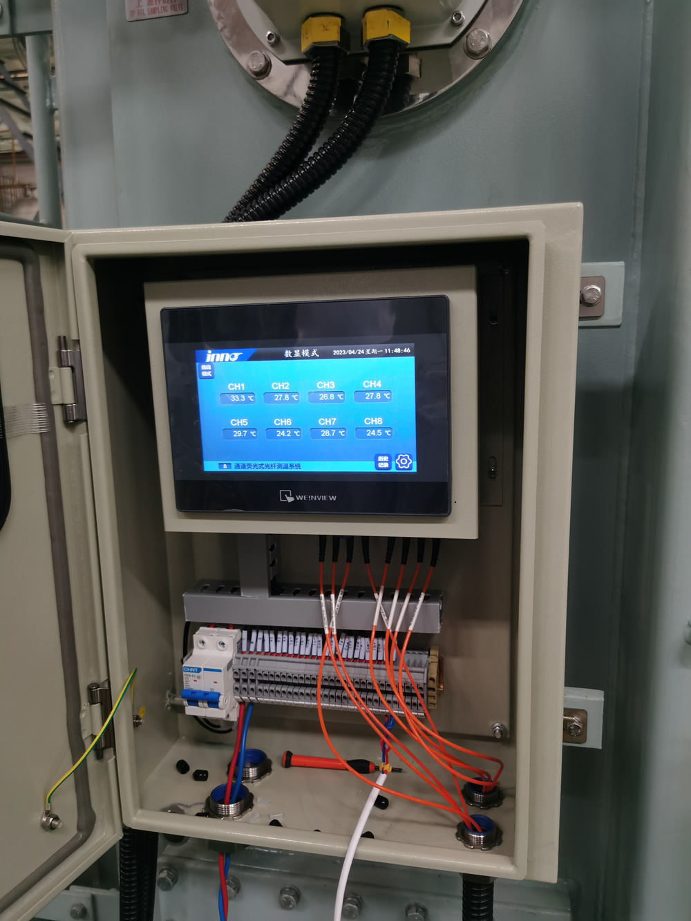
O método de utilização da medição de temperatura por fibra óptica para transformadores é instalar sensores fluorescentes de fibra óptica ou sensores de grade de fibra óptica em partes importantes do transformador., como enrolamentos e núcleos de ferro, e então determinar a temperatura detectando mudanças no tempo de vida da fluorescência ou no comprimento de onda da reflexão.
1. Princípio de medição de temperatura de fibra óptica de transformador
A medição da temperatura da fibra óptica do transformador é um método de detecção de temperatura baseado na tecnologia de detecção de fibra óptica, e seu princípio é o seguinte:
Princípio baseado nas características de fluorescência
O sensor de fibra óptica fluorescente é um método comumente usado para medição de temperatura de fibras de transformadores. Este sensor consiste em fibras ópticas multimodo e um objeto fluorescente montado em cima dele. Fluorescent substances emit fluorescence energy when stimulated by light of a certain wavelength (such as blue violet light). After the excitation is cancelled, the persistence of fluorescence afterglow depends on the characteristics of the fluorescent substance, environmental temperature factors, etc., and this excited fluorescence usually decays exponentially, with the decay time constant called fluorescence lifetime or fluorescence afterglow time 7. At different environmental temperatures, the decay of fluorescence afterglow varies, and the higher the temperature, the shorter the fluorescence lifetime. By detecting the fluorescence lifetime, the temperature value can be indirectly determined. Por exemplo, in dry-type transformer fiber optic temperature measurement, o sensor de temperatura de fibra óptica fluorescente utilizes this principle. The probe is embedded inside the insulation of the winding and directly contacts the winding conductor. When the winding temperature changes, the fluorescence lifetime of the fluorescent substance changes accordingly, which is detected by the sensor.
Taking Fuzhou Yingnuo Technology’s fiber optic temperature measurement technology as an example, its transformer winding fluorescence temperature measurement technology uses the energy absorbed by fluorescent molecules when the excited light beam enters the winding, and emits a fluorescence signal. By measuring the lifetime of the fluorescence signal, the temperature of the winding can be indirectly determined.
Principle of Fiber Bragg Grating
Fiber Bragg Grating is a passive filtering device formed by periodically modulating the refractive index of the fiber core. Para sensores de temperatura de grades de fibra óptica, quando a temperatura muda, the grating period and core refractive index of the fiber optic grating will change, resulting in a drift in the reflected wavelength. By detecting changes in reflection wavelength, temperature variation information can be obtained. Em transformadores, installing fiber Bragg grating temperature sensors on key parts such as windings and iron cores can sense temperature changes in these parts in real time. The fiber optic grating power transformer temperature measurement system adopts advanced fiber optic grating temperature measurement technology, which uses the change in reflected wavelength of fiber optic grating under temperature to measure the temperature of the transformer. This technology has the advantages of high insulation, not affected by electromagnetic environment, adequado para longa distância, transmissão de sinal de alta qualidade, e alta precisão de medição. It is suitable for use in high voltage and strong magnetic field environments such as electricity.
2. Steps of Transformer Fiber Optic Temperature Measurement Method
Preliminary preparation work
Determine temperature measurement requirements and locations: Primeiramente, it is necessary to clarify which parts of the transformer need to be measured for temperature. Por exemplo, para transformadores imersos em óleo, it may be necessary to measure the temperature of windings, núcleos de ferro, and oil passages; Para transformadores do tipo seco, the focus may be on the winding temperature. Determine the specific temperature measurement point location based on the type of transformer, ambiente operacional, and safety requirements. Por exemplo, if there is concern about the insulation performance being affected by overheating of transformer windings, it is necessary to install fiber optic sensors near the windings.
Choose appropriate fiber optic temperature measurement equipment: Select fiber optic temperature sensors, termômetros de fibra óptica, and other equipment based on factors such as temperature measurement range, requisitos de precisão, e adaptabilidade ambiental. If in a high-temperature environment, it is necessary to choose fiber optic sensors that can withstand high temperatures and have high measurement accuracy; Se estiver em um ambiente de forte interferência eletromagnética, priority should be given to using equipment with strong anti electromagnetic interference capabilities, como sensores de temperatura de fibra óptica fluorescentes, which have anti electromagnetic interference characteristics.
Verifique a integridade do equipamento: Antes da instalação, it is necessary to inspect the fiber optic temperature measurement equipment, including whether the fiber optic is damaged and whether the sensor is working properly. For optical fibers, it is necessary to check whether there are cracks or breaks in their appearance; For sensors, professional testing tools can be used to check their functionality, such as inputting standard temperature signals to see if the sensor’s output meets expectations.
Installation of Fiber Optic Sensors
Handling of installation location: If there is oil, pó, or other impurities at the location where the fiber optic sensor is installed, it needs to be cleaned first to ensure that the sensor can accurately measure temperature. Por exemplo, em transformadores imersos em óleo, if the sensor is to be installed near the oil passage, it is necessary to prevent impurities in the oil from affecting the contact between the sensor and the measured object.
Sensor fixation: Use appropriate fixing fixtures to install the fiber optic sensor in the predetermined position. If measuring winding temperature, it is necessary to ensure good contact between the sensor and the winding surface in order to accurately sense temperature changes. For the installation of fiber optic sensors in dry-type transformers, attention should be paid to avoiding mechanical damage to the sensors during the installation process, and ensuring that the sensors are firmly fixed and will not be displaced due to the vibration of the transformer. Ao mesmo tempo, it is important to maintain the normal curvature of the fiber optic sensor and avoid excessive bending that can cause damage to the fiber optic. Accessories such as fiber optic protective sleeves can be used for protection.
Fiber optic connection and wiring
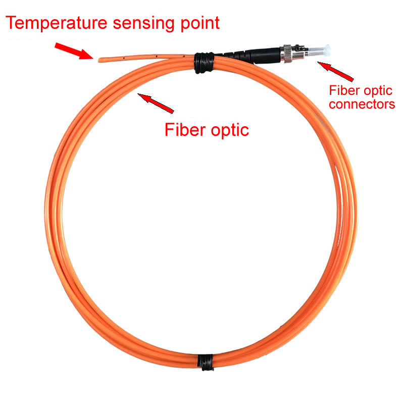
Fiber optic connection: Connect the fiber optic cable to the thermometer, and be careful to protect the fiber core during the connection process to avoid damage. Por exemplo, when connecting optical fibers, specialized fiber connectors should be used and the correct connection steps should be followed to ensure a stable and reliable connection. When plugging or unplugging fiber optic connectors, avoid applying excessive force to prevent damage to the fiber core.
Fiber optic cabling: Plan the routing path of fiber optic cables to avoid external compression, pulling, or wear as much as possible. If wiring is required around the transformer, it should be kept away from the heating components of the transformer to prevent the performance of the optical fiber from deteriorating due to high temperatures. Ao mesmo tempo, for longer fiber optic cabling, é necessário fazer um bom trabalho de fixação e etiquetagem para facilitar a manutenção e reparos posteriores.
Teste e calibração
Verificação funcional: Após concluir a instalação do cabo de fibra óptica, use um termômetro para verificação funcional. Medindo a temperatura ambiente e calibrando a temperatura, garantir a precisão e estabilidade do termômetro. Por exemplo, um objeto padrão com temperatura conhecida pode ser colocado próximo a um sensor de fibra óptica para verificar se a temperatura exibida pelo termômetro corresponde à temperatura real do objeto padrão. Se houver um desvio, o termômetro precisa ser calibrado.
Teste geral do sistema: Teste todo o sistema de medição de temperatura de fibra óptica, incluindo se a aquisição de dados, transmissão, and processing of multiple sensors working simultaneously are normal. Check whether the data can be accurately transmitted to the backend monitoring system and whether the temperature values of each temperature measurement point can be displayed correctly in the monitoring system.

3. Recommended Transformer Fiber Optic Temperature Measurement Equipment
Fluorescente sensor de temperatura de fibra óptica
característica
Forte capacidade anti-interferência: Due to its optical principle for temperature measurement, it is not affected by the strong electromagnetic field inside the transformer and can accurately measure temperature in high voltage and strong magnetic field environments. Por exemplo, in large substations, transformers are surrounded by complex electromagnetic environments, and fluorescent fiber optic temperature sensors can work stably, providing reliable data for transformer temperature monitoring.
High precision temperature measurement: Using the nonlinear relationship between fluorescence signal and temperature for temperature measurement can achieve high temperature measurement accuracy. Research has shown that its accuracy can reach 0.1 graus. This high-precision measurement helps to detect small changes in transformer temperature in a timely manner and provide early warning of potential fault risks.
Comprehensive temperature measurement capability: It can achieve comprehensive temperature measurement of transformer windings without being affected by local faults or complex working conditions, and can also perform real-time and continuous temperature monitoring. Durante a operação do transformador, the temperature distribution can be accurately monitored whether it is in normal operation or in case of abnormal conditions such as local overheating.
Caso de aplicação: O sensor de temperatura de fibra óptica fluorescente da Fuzhou Yingnuo Electronic Technology Co., Ltda. é amplamente utilizado no monitoramento de temperatura de transformadores do tipo seco e transformadores imersos em óleo. Em transformadores do tipo seco, este sensor pode se adaptar ao seu ambiente operacional especial e medir com precisão a temperatura do enrolamento do transformador; Em transformadores imersos em óleo, mudanças de temperatura em enrolamentos e passagens de óleo também podem ser monitoradas com precisão.
Sensor de temperatura de grade de fibra Bragg
característica
Alto isolamento e estabilidade: A própria grade de fibra Bragg é feita de fibras ópticas e tem bom desempenho de isolamento, que pode funcionar com segurança em ambientes de alta tensão. E sua estabilidade é boa, e os resultados da medição não são facilmente afetados por fatores externos. Por exemplo, em transformadores de alta tensão em sistemas de energia, sensores de temperatura de grade Bragg de fibra podem funcionar de forma estável por um longo tempo, providing guarantees for the safe operation of transformers.
High precision and sensitivity: It has high sensitivity to temperature changes, can accurately detect small temperature changes, and has high measurement accuracy. This enables timely detection of abnormal temperature increases in transformer temperature monitoring, and corresponding measures can be taken to prevent transformer failures from occurring.
Distributed measurement can be achieved: temperature measurements can be taken at multiple points along the axis of the fiber Bragg grating, and temperature information at different locations can be obtained by analyzing the reflected wavelength. The distributed measurement feature is very advantageous for comprehensive temperature monitoring of large transformers, as it can obtain temperature data of multiple key parts at once.
Caso de aplicação: The fiber Bragg grating temperature online monitoring system is applied to temperature monitoring of power transformers. This system utilizes the characteristics of fiber Bragg gratings to monitor the temperature changes of transformers in real time, and can transmit data to the monitoring center through the network, making it convenient for operation and maintenance personnel to monitor the operating status of transformers.
4. Analysis of Transformer Fiber Optic Temperature Measurement Example
Example of Fiber Optic Temperature Measurement for Dry type Transformers
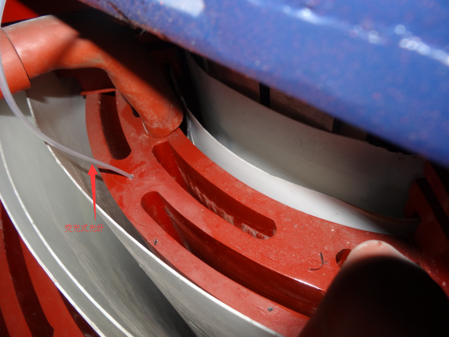
Composition and installation of temperature measurement system: A certain dry-type transformer adopts a sistema de medição de temperatura de fibra óptica fluorescente. The system consists of a fluorescent fiber optic temperature sensor, fibra óptica, and thermometer. The sensor is installed inside the insulation of the winding and in direct contact with the winding conductor. The optical fiber transmits the temperature signal collected by the sensor to the thermometer. Durante o processo de instalação, in order to ensure the normal operation of the sensor, the installation position was carefully selected to avoid external electromagnetic interference and mechanical damage. Por exemplo, installing the sensor in the middle of the winding can better reflect the average temperature of the winding. Ao mesmo tempo, special fixing fixtures are used to ensure close contact between the sensor and the winding when installing the sensor. A protective sleeve is also placed on the outside of the optical fiber to prevent damage during the operation of the transformer.
Temperature monitoring and fault warning: Durante a operação, the thermometer monitors the temperature of the transformer winding in real time. When the temperature rises to the set warning value, the system will issue a warning signal. Por exemplo, when the winding temperature reaches 120 ° C, a warning will be issued. Once the temperature approaches this value, a warning message will be sent to the operation and maintenance personnel through an audible and visual alarm or remote communication interface, reminding them to pay attention to the operation status of the transformer and check for overload, poor heat dissipation, e outras questões. If the temperature continues to rise and reaches the trip value (como 150 ° C), the system will control the transformer to trip to protect it from further damage.
Effect evaluation: Through long-term operation monitoring of the dry-type transformer fiber optic temperature measurement system, it was found that the system can accurately measure the winding temperature with an error within ± 0.5 ° C. Compared with the traditional PT100 temperature measurement method, the fiber optic temperature measurement system has higher accuracy and better anti-interference ability. Em operação real, there was once a situation where the temperature of a transformer increased due to a cooling fan failure. The fiber optic temperature measurement system promptly issued a warning signal, and the operation and maintenance personnel quickly took measures to repair the cooling fan after receiving the notification, avoiding accidents where the transformer was damaged due to overheating.
5. Example of Fiber Optic Temperature Measurement for Oil Immersed Transformers
Temperature measurement system and installation location: A temperature monitoring system based on fiber Bragg grating is installed on a certain oil immersed transformer. The fiber Bragg grating temperature sensor in the system is installed on the high and low voltage windings of the transformer, connected to the optical fiber through a fiber junction box, and transmits the collected temperature signal to the background monitoring system. When installing sensors, considering the oil flow and electric field distribution inside the oil immersed transformer, the sensors are installed near the oil passage support of the winding. This allows the sensors to better sense the temperature changes of the winding, while also avoiding damage caused by direct impact of oil flow on the sensors.
Analysis and application of temperature data: The backend monitoring system analyzes and processes the collected temperature data. Por um lado, it can display the temperature of various parts of the transformer in real time, and operation and maintenance personnel can intuitively view the temperature distribution through the monitoring interface; Por outro lado, by analyzing the historical records of temperature data, the operating status and fault risk of transformers can be predicted. Por exemplo, if it is found that the temperature of a winding continues to rise for a period of time, and the increase exceeds the normal range, it may indicate that there is a local overheating problem in the winding, and further inspection is needed to check for potential faults such as inter turn short circuits.
Actual benefits reflected: During the operation of the oil immersed transformer, the fiber optic temperature measurement system played an important role. Por exemplo, during the high temperature period in summer, when the transformer load is large, the real-time monitoring of the fiber optic temperature measurement system allows the operation and maintenance personnel to adjust the load of the transformer in a timely manner, avoiding the occurrence of high temperature caused by long-term overload operation. Ao mesmo tempo, during a regular maintenance of a transformer, a potential winding overheating problem was discovered through analysis of temperature data. After further inspection, it was found that the local resistance increased due to insulation aging of the winding, causing heating. Due to the timely detection and handling of this issue, potential transformer failures were avoided, ensuring the stable operation of the power system.
6. Precautions for Transformer Fiber Optic Temperature Measurement
Precautions during installation
Instalação do sensor
Position accuracy: When installing fiber optic sensors, ensure that they are installed in the predetermined and accurate position. For different parts of the transformer, como enrolamentos, núcleos de ferro, etc., the temperature distribution and variation patterns at each position are different. If the installation position of the sensor deviates, it may cause the measurement results to not accurately reflect the true temperature of that area. Por exemplo, when measuring the temperature of a winding hotspot, if the sensor is installed too far away from the hotspot area, it may underestimate the maximum temperature of the winding and fail to detect potential overheating risks in a timely manner.
Fixed firmness: Use appropriate fixing methods and accessories to firmly fix the sensor in the installation position. Transformers will generate vibration during operation. If the sensor is not firmly fixed, displacement may occur, affecting the accuracy of measurement and even causing poor contact between the sensor and the measured object, making it impossible to measure temperature normally. Por exemplo, in dry-type transformers, if the fiber optic sensor is not firmly fixed on the winding, it may rub against the insulation layer of the winding during transformer vibration, which not only affects temperature measurement but also may damage the insulation performance of the winding.
Avoid damaging the optical fiber: During the installation of sensors and wiring, special attention should be paid to protecting the optical fiber. Fiber optic is a key component for transmitting temperature signals. If the fiber optic is broken, bent with a small radius, or scratched, it may cause signal transmission interruption or attenuation, thereby affecting the normal operation of the temperature measurement system. Por exemplo, when optical fibers pass through holes in transformer casings, if the edges of the holes are not smoothed, the fibers may be scratched.
Wiring planning
Stay away from interference sources: The wiring of optical fibers should be kept away from possible interference sources, such as strong electromagnetic fields in transformers, high-temperature components, etc.. Strong electromagnetic fields may interfere with optical signals transmitted through optical fibers, and high-temperature components may degrade or even damage the performance of optical fibers. Por exemplo, parallel wiring of optical fibers and high-voltage leads of transformers should be avoided to prevent electromagnetic interference with optical fiber signals; Ao mesmo tempo, it is necessary to avoid placing the optical fiber near high-temperature components such as the heat sink of the transformer, to ensure that the optical fiber is within the normal working temperature range.
Reasonable path planning: It is necessary to plan the fiber optic cabling path well, making it as short as possible and easy to maintain. O cabeamento longo de fibra óptica não só aumenta os custos, mas também pode aumentar o risco de atenuação do sinal. Durante o processo de fiação, deve-se levar em consideração a estrutura do transformador e o ambiente circundante para evitar compressão, pulling, ou outros danos mecânicos às fibras ópticas. Por exemplo, a fiação de fibra óptica pode ser realizada ao longo do suporte ou calha do transformador, e fixado em intervalos regulares para evitar vibração da fibra óptica.
Precauções durante a operação
Inspeção regular
Inspeção do status do equipamento: Inspecione regularmente equipamentos de medição de temperatura de fibra óptica, incluindo sensores, termômetros, conectores de fibra óptica, e outros componentes. Verifique se o sensor está funcionando corretamente e se há algum dano ou fenômeno de envelhecimento; Verifique se a precisão da medição do termômetro ainda atende aos requisitos; Ensure that the fiber optic connector is securely connected without any looseness or oxidation issues. Por exemplo, a functional test can be conducted on the fiber optic sensor every six months to compare it with a standard temperature source and check if the measurement error of the sensor is within the allowable range.
Fiber integrity inspection: Check whether the fiber is damaged, quebrado, or corroded. The transmission loss of the optical fiber can be detected by a fiber optic tester. If an increase in transmission loss is found, it may indicate that there is a problem with the optical fiber and further investigation of the fault point is needed. Ao mesmo tempo, it is also necessary to check whether the protective cover of the optical fiber is intact. If the protective cover is damaged, it may expose the optical fiber to harsh environments, increasing the risk of damage.
Data monitoring and analysis
Real time data monitoring: It is necessary to monitor the temperature data collected by the fiber optic sistema de medição de temperatura in real time and pay attention to the trend of temperature changes. If abnormal fluctuations are found in temperature data, such as sudden increases or decreases, timely analysis and processing should be carried out. Por exemplo, when the temperature of a certain winding of a transformer suddenly rises, it may indicate problems such as overload, curto-circuito, or poor heat dissipation in the winding, and the operation of the transformer needs to be checked immediately.
Historical data utilization: Analyzing the historical records of temperature data can help identify potential issues and fault trends in transformers. By statistically analyzing long-term temperature data, we can understand the temperature changes of transformers under different loads, environmental temperatures, e outras condições, in order to predict possible fault situations in advance. Por exemplo, if it is found that the winding temperature of a transformer approaches the warning value during the high temperature period every summer, it can be considered to inspect and maintain the transformer’s cooling system before the arrival of summer.

Sensor de temperatura de fibra óptica, Sistema de monitoramento inteligente, Fabricante distribuído de fibra óptica na China
 |
 |
 |