 INNO glasvezel temperatuursensoren ,temperatuurbewakingssystemen.

Glasvezel Temperatuur Meetsysteem
E-mail: web@fjinno.net
WhatsAppen: +8613599070393
WeChat (China): +8613599070393

1、 Overzicht van onderstationbewakingssysteem
Het onderstationbewakingssysteem is een belangrijk onderdeel van het onderstationautomatiseringssysteem, voornamelijk gebruikt voor realtime monitoring en controle van de bedrijfsstatus van het onderstation om de veilige en stabiele werking ervan te garanderen. Het is gebaseerd op geavanceerde technologie en heeft meerdere functies en kenmerken. Bijvoorbeeld, het intelligente onderstationbewakingssysteem kan gegevens zoals arbeidsfactor en temperatuur bewaken om een normale werking te garanderen. De foutdiagnose en waarschuwingsfunctie kunnen potentiële fouten tijdig detecteren en waarschuwingen geven via de analyse van bewakingsgegevens, waardoor bedienings- en onderhoudspersoneel tijdig maatregelen kan nemen om ongevallen te voorkomen; The remote control function allows operation and maintenance personnel to remotely operate and adjust substation equipment, improving operation and maintenance efficiency; The data analysis and optimization function can analyze historical data and provide decision support for operational optimization to reduce costs; Simultaneously adopting advanced encryption technology and protective measures to ensure data and system security, preventing unauthorized access and attacks.
From the perspective of structural composition, the substation monitoring system has different hierarchical structures. It can generally be divided into interval layer, communication layer, and station control layer. The interval layer is a data acquisition, bescherming, and control device for equipment operating on site, such as comprehensive protection relays, protection control cabinets, multifunctional meters, enz. They are closely connected to primary equipment and are responsible for actual data acquisition and equipment control. The communication layer is a bridge for data transmission between the interval layer and the station control layer. Data is transmitted through communication cables/optical cables, with devices such as communication management machines and switches in between responsible for data distribution, overdragen, and storage of raw data. The station control layer is usually regarded as the backend, including computers, printers, monitoring screens, en andere apparaten. This layer needs to develop applications for the collected data to be displayed on the terminal screen. Afstandsbedieningsopdrachten worden ook vanuit deze laag verzonden en naar de intervallaag gestuurd voor uitvoering via de communicatielaag.
In aanvulling, het monitoringsysteem voor onderstations bestaat uit twee niveaus in termen van gecentraliseerde monitoring en beheer van energie en omgeving, namelijk het monitoringcentrum en de monitoringlocatie (die naar wens ook kan worden ontworpen als een bewakingscentrumarchitectuur met meerdere niveaus). Het monitoringcentrum bestaat uit databaseservers, het monitoren van servicedesks, printers, en andere apparatuur, verantwoordelijk voor het verzamelen van gegevens van monitoringapparatuur over het netwerk, statistische verwerking en analyse van apparaatinformatie, en het verstrekken van verschillende vormen van alarmering (zoals geluid en licht, gesproken aanwijzingen, uitgaande gesprekken, Sms, enz.); De monitoringlocatie maakt gebruik van een krachtige IBSU intelligente stationbewakingseenheid, which is responsible for collecting monitoring equipment parameters and processing intelligent device protocols in the substation. The collection equipment, intelligent air conditioning controller, intelligent battery detector, camera, sensor and other devices can be flexibly configured according to the site scale to monitor the power environment in the substation.
The substation monitoring system has diverse functions. The data acquisition and processing function obtains analog quantities (zoals actueel, spanning, active power, reactive power, machtsfactor, frequentie, en olie), switch quantities (such as equipment action and alarm signals, on load tap changer position signals, enz.), electrical energy and other data through measurement and control devices and communication interfaces, including DC sampling (converting AC signals into DC voltage signals suitable for data acquisition unit processing through transmitters and connecting them to the data acquisition unit), as well as collecting electrical energy from remote transmission devices and DC monitoring devices through communication interfaces. The collected data will be processed and stored. It also has control operation functions, alarm and processing functions, opeenvolging van gebeurtenissen (SOE) and accident recall functions, remote control unit (RTU) functies, clock synchronization functions, human-machine communication and operation management functions, and interface functions with other devices.
As an important part of the power supply and distribution system, the substation monitoring system can achieve integrated monitoring, vroege waarschuwing, and auxiliary operation and maintenance of power, omgeving, veiligheid, en andere aspecten. The system supports threshold customization, and auxiliary inspections can remotely monitor the operation status of the station building without the need for personnel to be on duty all day. It integrates station auxiliary subsystems to achieve comprehensive monitoring and internal and external intelligent scheduling. In case of sudden failures, it can timely understand the situation and command fault handling through video monitoring. These functions enable the station room to have fewer or no personnel on duty during operation, transforming the user maintenance mode from “passive repair mode” naar “active prevention mode”. It is widely used in substations, onderstations, switch stations, distribution rooms, box transformers and other scenarios, meeting the high-quality requirements of distribution network automation and preventing accidents.
2、 Temperature Monitoring in Substation Monitoring System
(1) The Importance of Temperature Monitoring
Tijdens de werking van het onderstation, the contact resistance of the electrical contacts of the primary equipment may increase due to factors such as equipment manufacturing, oxidatie van elektrische schokken, and arc impact, leading to a temperature rise. Wanneer de temperatuur naar een bepaald niveau stijgt, de mechanische en elektrische sterkte van de apparatuur zal afnemen, en in ernstige gevallen, it can cause short circuits or even damage to the electrical equipment, waardoor de veilige en stabiele werking van het elektriciteitsnet ernstig wordt bedreigd. Daarom, real-time monitoring of the temperature of electrical equipment in substations can help duty personnel detect problems as early as possible, elimineer verborgen gevaren, en zorgen voor de veilige werking van het energiesysteem.
(2) Traditional temperature monitoring methods and their drawbacks
The traditional temperature monitoring techniques for substations include infrared temperature measurement and wax sheet method. Infrared temperature measurement method utilizes the thermal effect principle of infrared radiation to determine the surface temperature of an object by detecting the infrared energy radiated by it. Echter, the measurement results of this method are greatly affected by environmental factors, such as high temperature, which can affect measurement accuracy and make it difficult to measure internal temperature. The wax sheet method involves attaching specially made wax sheets to the surface of equipment and determining whether the temperature exceeds a threshold based on the melting of the wax sheets. Echter, it can only provide a rough temperature range and has poor accuracy. Bovendien, most of these traditional methods require manual participation in device detection, which can easily lead to false alarms and missed detections. Vanwege het onvermogen om langdurige continue metingen uit te voeren, de nauwkeurigheid en real-time prestaties van monitoring zijn slecht.
(3) Toepassing van Glasvezeltemperatuurmeting bij temperatuurbewaking
1. Principe van Glasvezeltemperatuurmeting
Vezeloptisch temperatuurmeetsysteem is een nieuwe technologie die gebruik maakt van een bepaald kenmerk van lichtvoortplanting in optische vezels om real-time meting van de ruimtelijke temperatuurveldverdeling te bereiken. De optische vezel zelf is een temperatuursensor die gedistribueerde continue temperatuurdetectie langs het glasvezelpad kan uitvoeren. Het is voornamelijk gebaseerd op het principe van optische tijddomeinreflectometrie (OTDR) van optische vezels en het temperatuureffect van Raman-verstrooiing aan de achterkant van optische vezels. When a light pulse enters an optical fiber from one end, it propagates forward along the fiber. Due to the mirror like inner wall of the fiber, every point of the light pulse during propagation will reflect, and a small portion of the reflected light will be directed away from the light source, which is known as back Raman scattering light. The intensity of backscattered Raman light is temperature dependent, and by detecting the intensity of backscattered Raman light, the temperature at each point along the fiber can be calculated.
2. Toepassing van Fiber Optic Temperature Measurement in Substations
Fiber optic temperature measurement technology has broad application prospects in substations.
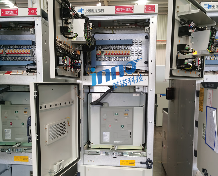
Equipment temperature monitoring: Fiber optic sensors can be installed on the surface of internal equipment such as transformers, stroomonderbrekers, en schakelapparatuur in onderstations om de temperatuur van apparatuur in realtime te bewaken, abnormale situaties tijdig op te sporen, en vermijd ongelukken veroorzaakt door oververhitting van apparatuur. Omdat glasvezelsensoren voordelen hebben zoals corrosieweerstand en sterke weerstand tegen elektromagnetische interferentie, ze zijn geschikt voor temperatuurbewaking van apparatuur in complexe elektromagnetische omgevingen zoals onderstations. Bijvoorbeeld, in een onderstation van het doostype, fluorescerende glasvezeltemperatuursensoren kunnen op belangrijke locaties zoals transformatoren worden geplaatst, stroomonderbrekers, en kabels om veranderingen in de omgevingstemperatuur in realtime te monitoren om de normale werking van de apparatuur te garanderen.
Bewaking van de kabeltemperatuur: Fiber optic sensors can be installed in cables to monitor cable temperature in real time and detect issues such as cable overheating and overload in a timely manner, ensuring the safety and stability of power transmission. For cables or high-voltage cable lines in the substation cable trench, due to the sensitivity of cable safety operation to temperature, the fiber optic temperature measurement system can perform distributed continuous measurement. Once there is a local abnormal temperature rise, it can quickly locate and provide accurate information for maintenance personnel.
3. Advantages of Fiber Optic Temperature Measurement
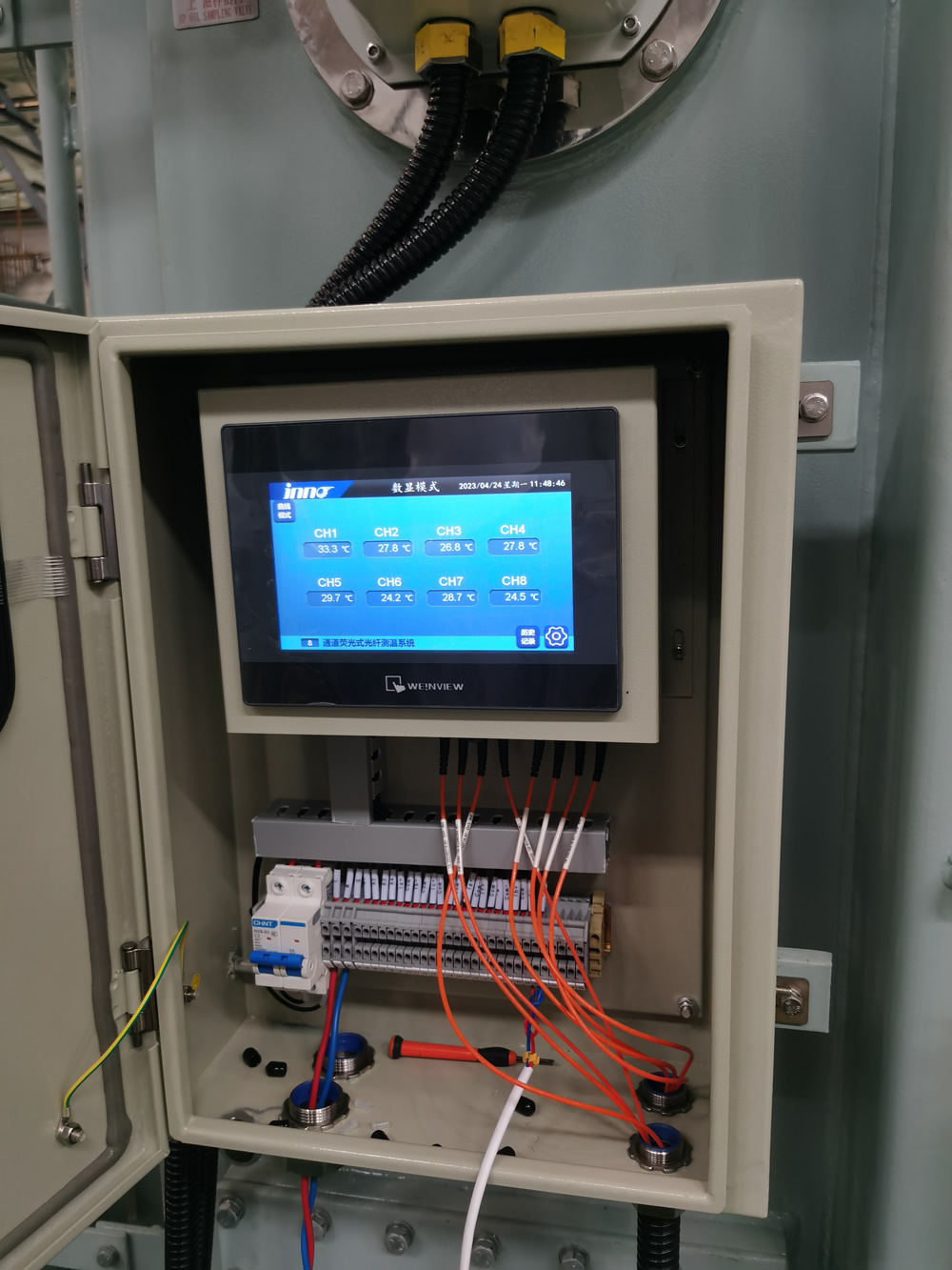
Hoge precisie: Fiber optic temperature sensors can achieve high-precision temperature measurement. Bijvoorbeeld, the temperature measurement accuracy of fluorescent fiber optic temperature sensors can reach 1 ℃, which can meet the high requirements of substations for temperature measurement.
High response speed: Some fiber optic temperature sensors have a response speed of up to seconds, which can achieve real-time monitoring of rapidly changing temperatures. This allows for timely capture of temperature information in the event of sudden changes in the operating status of equipment in the substation.
Multi point monitoring: Fiber optic cables can be flexibly deployed at various equipment, bus connection points, kabels, and other locations in the substation, enabling simultaneous temperature monitoring of multiple points in the substation and comprehensive understanding of the temperature distribution in the substation.
High safety and adaptability: Fiber optic itself is a non-metallic material with characteristics such as corrosion resistance and electromagnetic interference resistance. It can work stably in high voltage and strong electromagnetic interference environments such as substations, and will not cause additional interference to the electromagnetic environment inside the substation. Tegelijkertijd, there are no safety hazards such as electric shock. In aanvulling, the transmission distance of optical fiber is relatively long, reaching tens or even hundreds of meters, which is suitable for temperature monitoring needs in large spatial layouts of substations.
3、 Voltage and current monitoring in substation monitoring system
(1) The Importance of Voltage Monitoring
Voltage is a key parameter in the operation of substations. The voltage level inside the substation directly affects the operation status of power equipment and the quality of electrical energy. If the voltage is too high, it may cause equipment insulation breakdown, overvoltage protection action, enz., shortening the service life of the equipment. Bijvoorbeeld, transformers may experience iron core saturation under high voltage, resulting in additional losses and heat generation, affecting their normal operation. Echter, a low voltage can affect the normal functioning of power equipment, such as causing a decrease in motor torque and preventing the equipment from starting properly. Daarom, accurate monitoring of the voltage inside the substation is a necessary means to ensure the safe and stable operation of the substation and the normal supply of electrical energy.
(2) Voltage monitoring method
1. Direct detection method
The direct detection method is a relatively simple and direct voltage monitoring method. This method directly detects voltage by connecting electronic instruments such as oscilloscopes and voltmeters. Bijvoorbeeld, in some laboratory environments or simple substation maintenance scenarios, an oscilloscope can be connected to measurement points in the circuit to visually observe the waveform and amplitude of the voltage. Echter, when using this method, special attention needs to be paid to selecting appropriate electronic instruments to ensure measurement accuracy and safety. Tegelijkertijd, certain modifications need to be made to the tested circuit in order to connect the voltage to the electronic instrument for measurement.
2. Sensor detection method
De sensordetectiemethode zet spanning om in een signaal dat geschikt is voor elektronische metingen door specifieke typen sensoren te installeren. Bijvoorbeeld, bij spanningsbewaking van onderstations, Er kunnen elektrische veldsensoren worden gebruikt. Sensoren kunnen de elektrische veldsterkte detecteren die door spanning wordt gegenereerd, zet het elektrische veldsignaal om in een elektrisch signaal dat kan worden herkend en verwerkt door elektronische meetapparatuur, en verkrijg vervolgens de spanningswaarde op basis van de conversierelatie. Deze detectiemethode is meer geschikt voor hoogspanningsscenario's waarbij het niet handig is om meetinstrumenten direct aan te sluiten, en kunnen sensoren eenvoudig integreren in geautomatiseerde monitoringsystemen voor continue monitoring op lange termijn.
3. Op transformatoren gebaseerd monitoringschema
Bij spanningsmeting van onderstations, the characteristics of transformers can be utilized for voltage monitoring. In some substation control systems, the DC bus voltage monitoring of the frequency converter can be achieved through switching transformers. Bijvoorbeeld, the primary voltage of a switching transformer is the bus voltage, and a set of windings is added to the secondary side as a sampling output of the bus voltage. The output voltage of the secondary side changes linearly with the change of the primary input voltage, which can both isolate strong and weak electricity and reduce voltage. Dan, the sampled signal is processed and sent to the corresponding control chip, such as sending it to DSP for A/D sampling, to achieve various protection works.
(3) The Importance of Current Monitoring
Current monitoring in substations is equally crucial. The magnitude of current reflects the load situation of power equipment during operation, as well as the efficiency and effectiveness of power transmission. Excessive current can cause overload, verwarming, and even damage to power equipment. Bijvoorbeeld, if a transformer is subjected to loads exceeding its rated current for a long time, it can cause the winding temperature to rise, accelerate insulation aging, and shorten equipment life. A too small current may indicate that the equipment is not functioning properly or there is a fault in the power transmission process (such as a broken line). In aanvulling, accurate monitoring of the current magnitude of each branch and equipment in complex substation power grid structures is helpful for the scheduling and control optimization of the power grid, such as determining a reasonable flow direction for power distribution.
(4) The method of current monitoring
1. Direct detection method
Similar to the direct detection method of voltage, the direct detection method can also be used for current monitoring. Measure current directly by connecting electronic instruments such as ammeters. Echter, this method may be limited by instrument range when measuring large currents, and also requires appropriate modifications to the circuit in order to connect to the measuring instrument for measurement. It may be used in current measurement scenarios during the detection of small current branches or equipment debugging in substations.
2. Sensor detection method
The sensor detection method can use various types of sensors in current monitoring.
Magnetic field sensor: Based on the principle of current generating a magnetic field, the magnetic field sensor can detect changes in the magnetic field around the current and infer the magnitude of the current accordingly. In onderstations, magnetic field sensors are more suitable for non-contact measurement of high currents in busbars or large equipment. Bijvoorbeeld, a Hall element is a magnetic field sensor that operates based on the Hall effect.
Current transformer: It is a device specifically used for current monitoring, and its basic principle is to use the magnetic field induction circuit in the current carrying coil to reduce the voltage of the detection signal through a transformation ratio. Widely used in substation monitoring systems. When using a current transformer, it is important to select the appropriate current transformer and perform appropriate circuit modifications to connect the current to the transformer for voltage transformation, and then measure and process the converted signal. Bijvoorbeeld, when measuring the high current in high-voltage lines inside a substation, the high current is converted into a smaller current signal through a current transformer in a certain proportion, which is used for subsequent measurement, bescherming, and monitoring operations.
4、 Composition and Function of Substation Monitoring System
(1) Composition of Substation Monitoring System
1. Information collection system
This system includes various monitoring devices and data acquisition devices, mainly used to collect operational data and status information of various devices in substations, zoals spanning, huidig, temperatuur, vochtigheid, druk, enz. When monitoring transformers, it is necessary to collect temperature related data such as oil temperature and winding temperature. Voltage transformers and current transformers are responsible for measuring voltage and current values, while various sensors (zoals vochtigheidssensoren, druk sensoren, enz.) can monitor environmental humidity, pressure conditions inside equipment, enz. These collection devices collect data from various devices and environments in preparation for subsequent analysis and processing, and play a role as the data source in the entire substation monitoring system.
2. Data communication system
The data communication system is responsible for transmitting the data obtained by the collection system to other parts, ensuring the transmission of data between different devices and modules. The communication method can be wired communication, such as using communication cables, optical cables, enz. for data transmission. Bijvoorbeeld, in fiber optic temperature measurement systems, data is transmitted through optical fibers; It can also be wireless communication, such as using ZigBee wireless network technology to transmit some sensor measurement data, such as temperature data collected by wireless temperature sensors, which can be transmitted to the control room host through ZigBee network. During the communication process, communicatiebeheermachines, schakelaars, en andere apparaten nemen deel aan de distributie en het opslagbeheer van gegevens om de efficiëntie en nauwkeurigheid van de gegevensoverdracht te garanderen.
3. Monitoring Center-systeem
Het monitoringcentrumsysteem is het kernonderdeel van het substationmonitoringsysteem, bestaat voornamelijk uit databaseservers, het monitoren van servicedesks, printers en andere apparatuur. De databaseserver wordt gebruikt om enorme monitoringgegevens op te slaan die zijn verzameld van verschillende apparaten in het onderstation, en te classificeren, winkel, beheren, en deze gegevens opvragen. De monitoringservicedesk biedt een bedieningsinterface voor bedienings- en onderhoudspersoneel. Op deze interface, bedienings- en onderhoudspersoneel kan intuïtief de bedrijfsparameters bekijken, operationele status, en andere gerelateerde monitoringinformatie van onderstationapparatuur. Als er abnormale situaties worden aangetroffen, they can be handled through this platform. Printers can be used to print important monitoring reports, data statistics, and other materials for operation and maintenance personnel to analyze and archive.
4. Control system
The control system includes various switches and actuators, which can achieve automatic control and scheduling of various equipment in the substation. Bijvoorbeeld, when the current of a certain line in the substation is detected to be too high, the control system can disconnect the circuit breaker in the control circuit to avoid overloading and damage to the line. Bijvoorbeeld, according to the voltage adjustment instructions given by the monitoring center, the control system can automatically operate the on load tap changer of the transformer, thereby achieving voltage adjustment to ensure the safe and stable operation of the substation.
5. Human machine interface system
The human-machine interface system serves as a window for operation and maintenance personnel to interact with the substation monitoring system, and its design requires simplicity, ease of use, and intuitive clarity. It can display the layout of substation equipment, equipment operation status (such as connection status, operatie, stop, fault status, enz.), monitoring data (displaying voltage, huidig, temperatuur, enz. in the form of charts, cijfers, enz.) and other information in a graphical interface. Through this interface, operation and maintenance personnel can easily perform remote control operations on equipment (such as remote closing and opening operations), set monitoring parameters (such as temperature warning thresholds, voltage upper and lower limits, enz.), and view system alarm information (display equipment faults, parameter abnormalities, and other alarm information through sound, licht, text prompts, enz.).
6. Power supply guarantee system
The power supply guarantee system mainly includes equipment such as UPS power supply and backup generator set. Its function is to ensure the stable operation of the substation monitoring system and prevent sudden events such as power outages from affecting the system. Due to the interruption of power supply in the substation, if the monitoring system cannot work properly, it will result in the inability to grasp the real-time operation status of the substation, which may cause various safety accidents. UPS power supply is rechargeable and backup during normal power supply. In case of power interruption, it can quickly provide temporary power support for monitoring system equipment. The backup generator set can provide continuous power supply to the substation monitoring system and other important equipment in extreme situations such as long-term power outages, to ensure the safe and stable operation of the substation.
(2) Functions of substation monitoring system
1. Data collection and processing functions
The substation monitoring system can collect various types of data, including analog quantities (zoals spanning, huidig, machtsfactor, temperatuur, enz.), switch quantities (such as equipment operation status conversion signals, protection device action signals, enz.), electrical energy (used to measure equipment electricity consumption, enz.), en andere gegevens. Op het gebied van dataverzameling, it can obtain data directly connected to devices through measurement and control devices. Bijvoorbeeld, a multifunctional electricity meter calculates power factor, electrical energy, and other data by measuring basic parameters such as voltage and current of the line; Information from various intelligent devices, such as DC monitoring devices and remote transmission devices for electrical energy, can also be obtained through communication interfaces. The collected data will be processed accordingly, such as signal transformation and numerical conversion (such as converting the collected analog signal into a digital signal for computer processing) during the process of analog signal acquisition. The switch data will be processed for state judgment, displacement recording, enz. The processed data will be stored in the database server for subsequent query, analyse, and use.
2. Control operation function
The control system can control the equipment in the substation as needed. Bijvoorbeeld, remote operation can be carried out, en het bedienings- en onderhoudspersoneel kan controle-instructies geven via de mens-machine-interface van het meldkamersysteem, die via de communicatielaag naar de apparatuurbesturingsinrichting in de intervallaag worden verzonden, om openings- en sluitingsbewerkingen op de schakelapparatuur uit te voeren (zoals stroomonderbrekers, scheidingsschakelaars, enz.) van het onderstation, pas de belastingwisselaar van de transformator aan, en verander het spanningsniveau; Automatische controlewerkzaamheden kunnen ook worden uitgevoerd, zoals het beperken van de vooraf ingestelde werkparameters zoals spanning en stroom. Wanneer de werkelijke bedrijfsparameters de limiet overschrijden, het besturingssysteem past de werking automatisch aan zonder handmatige tussenkomst, zoals het automatisch verminderen van de belasting van de transformator om overbelasting te voorkomen, adjusting the switching state of the capacitor to regulate reactive power to stabilize the voltage.
3. Alarm and processing functions
When the monitoring system detects abnormal equipment operation or data exceeding the normal set range, the system can promptly issue an alarm signal. There are various forms of alarms, including sound and light alarms, gesproken aanwijzingen, uitgaande gesprekken, SMS notifications, enz. Bijvoorbeeld, when the oil temperature of the transformer exceeds the set upper limit of the safe temperature, the monitoring center system will automatically trigger the sound and light alarm device to remind the on duty personnel in the station; Tegelijkertijd, alarm information can be sent to remote operation and maintenance personnel, management personnel, and other relevant personnel through voice call or SMS notification functions. Bovendien, the system can record detailed information about the alarm event during the alarm, such as the time of the alarm occurrence, equipment name, specific abnormal data, enz., in order to analyze the cause of the fault afterwards. With the development of intelligent technology, the system can also perform some preliminary emergency handling operations based on alarm information, such as automatically reducing equipment load, switching backup equipment, enz., to prevent further expansion of faults.
4. Event sequence of events (SOE) and accident recall function
This function can record events that occur in the substation in chronological order. The SOE function accurately records the precise time sequence of various events (such as equipment state transition events, protective device action events, enz.), which can be precise to millisecond or even finer time scales, which helps to analyze the development process of faults afterwards. The accident recall function allows the system to record the operational data and status of relevant equipment during a period of time before the occurrence of a fault event (which can be set according to system settings, such as minutes to hours before the fault), including voltage, huidig, equipment switch status, and other information, providing detailed data basis for analyzing the cause of the accident and formulating preventive measures. Bijvoorbeeld, when a power outage occurs in a substation, the accident recall function can be used to query the load situation of the transformer, the current situation of each line, and the opening and closing status of equipment such as circuit breakers before the power outage, thereby assisting engineers in determining the starting event and chain reaction process of the accident.
5. Terminaleenheid op afstand (RTU) functie
The substation monitoring system can achieve remote control function, transmitting various data (such as equipment operation status, measurement data, enz.) inside the substation to the higher-level dispatch center or remote monitoring center, and receiving control instructions from the higher-level. This function is very important in the centralized dispatching management of the power grid, so that the dispatching center can control the operation of multiple substations in real time, so as to achieve macro regulation and control of the substation. Bijvoorbeeld, when there is an imbalance in the distribution of power load within the power grid area, the dispatch center can send instructions to the substation through remote control functions to adjust the output power of transformers or adjust the connection method of lines to balance the power load.
6. Clock synchronization function
It is very important to maintain clock synchronization between the various devices in the substation and with the entire power grid system. The clock synchronization function of the monitoring system can ensure that the event time recorded by all devices is consistent, providing accurate time basis for event sequence recording, fault analysis and other operations. This function is achieved through time synchronization devices such as satellite clock receivers, which enable the clocks of equipment in the substation to run according to a unified standard time, avoiding problems such as data recording confusion and difficulty in fault analysis caused by inconsistent clocks.
7. Human machine communication and operation management functions
The human-machine connection and operation management function provides operation and maintenance personnel with the means to manage and operate the substation monitoring system. In the human-machine interface system, operation and maintenance personnel can easily perform various operations, such as viewing equipment operating status, controlling equipment operation, setting monitoring parameters, alarminformatie ontvangen, enz. as mentioned earlier. Tegelijkertijd, it can also perform system operation management operations, including system settings (such as device numbers, communication parameters, enz.), beheer van gebruikersrechten (het instellen van de toestemmingsbereiken van verschillend personeel voor systeembewerkingen), gegevensback-up en herstelbeheer (regelmatig een back-up maken van monitoringgegevens om gegevensverlies te voorkomen, en het uitvoeren van gegevensherstelbewerkingen wanneer dat nodig is), enz., om de betrouwbare werking en het redelijke gebruik van het onderstationbewakingssysteem te garanderen.
8. Interfacefunctie met andere apparaten
Het onderstationbewakingssysteem moet een goede interfaceverbinding tot stand brengen met diverse andere apparatuur binnen het onderstation en externe gerelateerde systemen. Binnen het onderstation, het monitoringsysteem moet communiceren en communiceren met verschillende primaire apparatuur (zoals transformatoren, rails, schakelapparatuur, enz.) en secundaire apparatuur (zoals beveiligingsapparatuur, meet- en regelapparatuur, enz.) om monitoring en controle van deze apparaten te bereiken. Extern, Het kan nodig zijn om te communiceren met het elektriciteitsnetverzendingssysteem, energiemeetsysteem, milieumonitoringsysteem, enz., Bijvoorbeeld, om te communiceren met het elektriciteitsnetverzendingssysteem om datarapportage en instructieontvangst te realiseren, deel het elektriciteitsverbruik en andere gegevens met het energiemeetsysteem, en verkrijg milieugegevens rond het onderstation van het milieumonitoringsysteem (zoals temperatuur, vochtigheid, windrichting, windsnelheid, en andere meteorologische gegevens die de werking van het onderstation kunnen beïnvloeden), om de algehele operationele efficiëntie te verbeteren, veiligheid, en betrouwbaarheid van het onderstation.

Glasvezel temperatuursensor, Intelligent monitoringsysteem, Gedistribueerde glasvezelfabrikant in China
 |
 |
 |