 INNO 광섬유 온도 센서 ,온도 모니터링 시스템.
Internal battery temperature monitoring is the continuous, real-time measurement of temperatures at critical locations 내부에 battery packs — including individual cell surfaces, inter-cell gaps, 부스바 연결, and module cores — rather than relying solely on external casing or ambient readings.
The system utilizes precision sensors, 신호 처리 장치, and communication interfaces to capture thermal data under varying charge, 해고하다, 및 환경 조건.
Critical for preventing thermal runaway, internal temperature monitoring maximizes battery pack lifespan, 안전, and operational reliability across energy storage, electric vehicle, 및 산업용 애플리케이션.
Advanced monitoring technologies, ~와 같은 형광성 광섬유 온도 센서, enable precise and maintenance-free measurement at multiple points within battery modules and packs without introducing short-circuit risk.
Temperature data supports automated alarms, protective disconnection, cooling system management, charge rate optimization, 위험 완화 및 예측 유지 관리에 필요한 상세한 상태 분석.
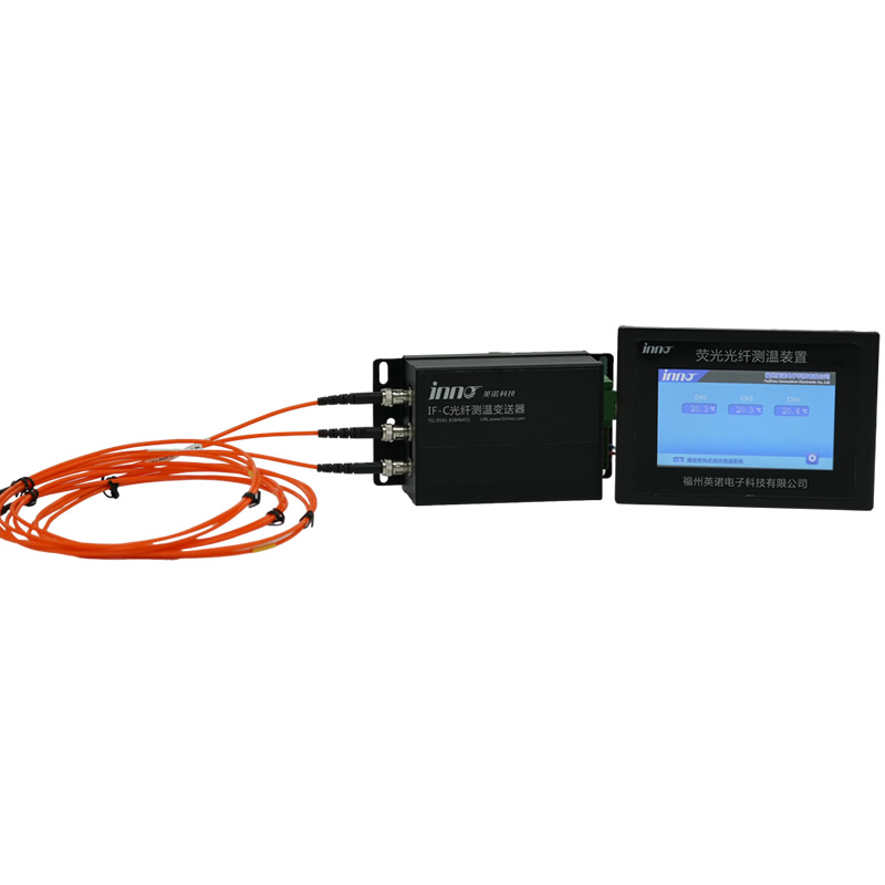
배터리 팩 광섬유 온도 모니터링 시스템
이메일: web@fjinno.net
왓츠앱: +8613599070393
목차
- 내부 배터리 온도 모니터링이란 무엇입니까??
- 표면 전용 모니터링이 충분하지 않은 이유
- 7 배터리 팩에 내부 온도 모니터링이 필요한 이유
- 배터리 팩의 열 폭주 이해
- 배터리 온도 센서 유형: 광섬유 vs RTD vs 열전대 vs NTC
- 배터리 팩의 주요 모니터링 포인트
- 배터리 화학에 따른 내부 모니터링 요구 사항: LFP 대 NMC 대 NCA
- 배터리 온도 모니터링 시스템을 선택하는 방법
- 배터리 온도 모니터링: 일반적인 문제 및 해결 방법
- 배터리 온도 모니터링 관련 국제 표준
- 실제 적용 사례
- 배터리 온도 분석을 기반으로 한 예측 유지 관리
- 배터리 온도 모니터링의 미래 동향
- 자주 묻는 질문: 배터리 팩 온도 모니터링
내부 배터리 온도 모니터링이란 무엇입니까??

정의
Internal battery temperature monitoring refers to the placement of temperature sensors at locations 내부에 the battery pack structure — directly on cell casings, between adjacent cells, on busbar and tab connections, and within module housings — to capture the actual thermal state of the battery in real time. This contrasts with external monitoring, which measures only the outer surface or ambient temperature of the pack enclosure.
중요한 이유
The internal temperature of a battery cell can differ from its external surface temperature by 5–20°C depending on charge rate, state of health, 및 냉각 시스템 효율성. 고속충전 중, abuse conditions, or internal fault development, this discrepancy becomes far larger. Only internal monitoring provides the thermal visibility required for effective safety protection and performance optimization.
핵심 구성요소
A complete internal monitoring system consists of temperature sensing probes installed at critical internal locations, signal transmission media (optical fiber or electrical cable), a signal processing and demodulation unit, and a communication interface (typically RS485 Modbus RTU) for integration with the battery management system (BMS), SCADA, or facility-level energy management platform.
표면 전용 모니터링이 충분하지 않은 이유
열 지연
Surface-mounted sensors respond to internal thermal events only after heat has conducted through the cell casing and module housing to reach the sensor location. This introduces a delay of seconds to minutes — a critical time gap during which a developing thermal runaway event can accelerate beyond the point of intervention.
Temperature Gradient Blindness
Battery packs contain significant internal temperature gradients. Cells in the center of a densely packed module can operate 10–15°C hotter than cells at the module edge. Surface-only monitoring typically captures only the cooler peripheral temperature, giving a false sense of safety while interior cells may be approaching dangerous limits.
Connection Point Invisibility
버스바 연결, cell tabs, and welded joints inside the battery pack are common sites of resistance heating caused by degraded connections, 부식, 아니면 제조상의 결함. These hotspots are invisible to external surface sensors but are directly detectable by internal 광섬유 온도 프로브 placed at or near these connection points.
Cooling System Assessment
Without internal temperature data at multiple locations within the pack, it is impossible to accurately assess whether the cooling system is maintaining acceptable temperature uniformity across all cells. Uneven cooling causes uneven aging, capacity fade, and increased risk of localized thermal events — all invisible to external monitoring alone.
7 배터리 팩에 내부 온도 모니터링이 필요한 이유

Reason 1: Early Detection of Thermal Runaway
Thermal runaway in lithium-ion cells begins with an internal temperature rise of just 1–5°C above normal, often caused by an internal short circuit or dendrite growth. By the time this heat conducts to the external surface, the internal reaction may have already become self-sustaining. Internal sensors detect the earliest stage of the thermal excursion — when the event can still be stopped by module isolation, 냉각 활성화, or controlled discharge. This early detection capability is the single most important reason for internal monitoring, and it is the reason that 광섬유 온도 모니터링 시스템 are increasingly specified for safety-critical battery applications.
Reason 2: Accurate Thermal Mapping for Performance Optimization
Battery pack performance is directly affected by temperature uniformity. Cells operating at different temperatures age at different rates, deliver different capacities, and exhibit different internal resistance characteristics. Internal multi-point monitoring creates a real-time thermal map of the entire pack, enabling the BMS to balance charge distribution, adjust cooling, and optimize C-rate limits to maximize both performance and cycle life across every cell in the pack.
Reason 3: Preventing Thermal Propagation Between Cells
In a densely packed battery module, cells are separated by only millimetres. If one cell enters thermal runaway, heat transfers to adjacent cells through conduction, 전달, and radiation — potentially triggering a cascade that destroys the entire module or pack within minutes. Internal sensors positioned between cells detect the temperature spike at the propagation boundary, giving the protection system the maximum possible time to isolate the affected area and activate fire suppression before the chain reaction establishes.
Reason 4: Connection and Busbar Hotspot Detection
High-current connections within battery packs — including cell tabs, welded joints, bolted busbars, and module-to-module interconnects — are vulnerable to resistance heating from loose connections, 부식, or weld defects. A connection that appears mechanically sound may still develop elevated resistance over time. Internal temperature monitoring at these critical junction points provides continuous hotspot surveillance, detecting developing faults long before they progress to arcing, melting, or fire. The same monitoring principle is used in 개폐기 온도 모니터링 for identical reasons.
Reason 5: Extended Battery Cycle Life and Reduced Degradation
Lithium-ion battery degradation follows a well-documented temperature dependency. For every 10°C increase in average operating temperature above optimal, calendar aging accelerates significantly and cycle life can be reduced by 30–50%. Internal monitoring enables the BMS to keep every cell within the optimal temperature window — not just the average pack temperature — by adjusting cooling, power limits, and charge profiles based on actual internal thermal conditions rather than estimated or surface-measured values.
Reason 6: Safety Compliance and Certification Requirements
International safety standards including UL 9540A, NFPA 855, IEC 62619, and UN 38.3 impose increasingly stringent requirements for battery thermal management and monitoring. Insurance underwriters and grid operators require documented evidence of comprehensive thermal protection. Internal temperature monitoring with traceable accuracy specifications — such as the ±0.5°C accuracy delivered by 형광성 광섬유 온도 센서 — provides the monitoring capability and data trail that satisfies these regulatory, 보험, and certification requirements.
Reason 7: Reduced Total Cost of Ownership
While internal monitoring systems require initial investment, the total cost of ownership is substantially lower than the cost of battery failures, 보증 청구, 계획되지 않은 가동 중지 시간, fire damage, and accelerated cell replacement caused by inadequate thermal management. Fluorescent fiber optic monitoring systems require zero maintenance, 재보정 없음, and no sensor replacement over a 25+ year service life — eliminating recurring maintenance costs entirely and delivering the lowest lifecycle cost of any monitoring technology available for battery applications.
배터리 팩의 열 폭주 이해
What Is Thermal Runaway?
Thermal runaway is a self-reinforcing exothermic reaction within a lithium-ion cell that occurs when internal temperature exceeds a chemistry-dependent critical threshold — typically between 130°C and 250°C. Once initiated, the reaction generates heat faster than it can be removed, driving the temperature higher and triggering decomposition of the electrolyte, separator, and electrode materials. The result is violent gas venting, flame emission, 폭발 가능성도 있고.
Stages of Thermal Runaway
단계 1 — Initial Heat Generation (Detectable by Internal Monitoring)
An abnormal condition — internal dendrite short circuit, overcharge, 기계적 손상, or localized cooling failure — causes a gradual internal temperature rise of 1–5°C above normal. This is the critical detection window. Internal fiber optic sensors can identify this deviation; external surface sensors typically cannot.
단계 2 — Accelerating Reaction (Intervention Window)
As internal cell temperature exceeds 80–120°C, the solid electrolyte interphase (SEI) layer begins to decompose, releasing additional heat. The reaction becomes self-sustaining. 에이 광섬유 온도 모니터링 시스템 with sub-second response time can detect this acceleration and trigger protective actions — module disconnection, enhanced cooling, or emergency discharge.
단계 3 — Full Thermal Runaway (Containment Only)
Once the critical threshold is exceeded, violent venting, 불, and potential explosion occur. Heat radiates to adjacent cells, potentially triggering cascading failure. At this stage, prevention is no longer possible — only containment. The objective of internal monitoring is to ensure that intervention always occurs at Stage 1 or early Stage 2.
Chemistry-Dependent Thermal Runaway Onset Temperatures
| Battery Chemistry | Thermal Runaway Onset Temperature | Relative Severity |
|---|---|---|
| NCA (Nickel Cobalt Aluminium) | ~150°C | High — rapid energy release |
| NMC (Nickel Manganese Cobalt) | ~200°C | High — significant gas generation |
| LFP (Lithium Iron Phosphate) | ~270°C | Moderate — slower onset, 낮은 에너지 |
| LTO (Lithium Titanate) | >280℃ | Low — most thermally stable |
배터리 온도 센서 유형: 광섬유 vs RTD vs 열전대 vs NTC

Choosing the right sensor technology for internal battery temperature monitoring carries direct safety implications. The four main technologies differ significantly in accuracy, 전자기 간섭 (EMI) immunity, short-circuit risk, and suitability for internal placement within battery packs.
| 특징 | 형광 광섬유 센서 | NTC 서미스터 | RTD (Pt100 / Pt1000) | 열전대 (Type K/J) |
|---|---|---|---|---|
| 측정 정확도 | ±0.1~0.5°C | ±1~2°C | ±0.5~1°C | ±1~2°C |
| EMI / 고전압 내성 | ✅ 완전 면역 (no metal, 유전체) | ⚠️ 일부 (susceptible to noise) | ❌ 민감함 (차폐가 필요합니다) | ❌ 민감함 (차폐가 필요합니다) |
| Short-Circuit Risk Inside Battery | ✅ Zero (완전 유전체) | ❌ Present (metallic leads) | ❌ Present (금속 원소) | ❌ Present (금속 접합) |
| Internal Cell/Module Placement | ✅ Safe (no conductive path) | ⚠️ Surface only recommended | ❌ Unsafe for internal placement | ❌ Unsafe for internal placement |
| 응답 시간 | < 1 두번째 | 1–5 seconds | 2–10 seconds | 1–3 seconds |
| 작동 온도 범위 | -40°C ~ +260°C | -40°C ~ +150°C | -200°C ~ +600°C | -200°C ~ +1350°C |
| 장기적인 안정성 | ✅ 훌륭함 (드리프트 없음) | ⚠️ 보통 (시간이 지남에 따라 표류하다) | ✅ 좋음 | ⚠️ 보통 (prone to drift) |
| 유지 보수 요구 사항 | ✅ 유지 관리가 필요 없음 | Periodic replacement | 주기적 교정 | 빈번한 교정 |
| 다중 지점 기능 | ✅ 최대 64 단위당 채널 | Limited by wiring complexity | 포인트별로 별도의 센서 | 포인트별로 별도의 센서 |
| 서비스 수명 | > 25 연령 | 3-5년 | 5-10년 | 2-5년 |
| 총 소유 비용 | ✅ 최저 (교정/교체 없음) | 보통의 | 보통의 | 더 높은 (빈번한 교체) |
| 최고의 응용 프로그램 | Internal cell/module monitoring, safety-critical packs | Low-cost BMS integration, surface monitoring | External oil/ambient monitoring | Low-cost auxiliary monitoring |
결론: For internal placement within battery packs where short-circuit risk must be eliminated and EMI immunity is essential, fluorescent fiber optic sensors are the superior choice. NTC thermistors remain practical for surface-mounted BMS integration in cost-sensitive applications where the limitations are understood and accepted. For a detailed technical comparison across all sensor types, 을 참조하다 광섬유 온도 측정 시스템 FAQ.
배터리 팩의 주요 모니터링 포인트
Individual Cell Surface
The most critical monitoring location is directly on the cell casing at the point of highest thermal stress. For prismatic and pouch cells, this is typically the center of the largest face. For cylindrical cells, sensors are placed on the cell body near the positive terminal where internal current collector resistance generates the most heat.
Inter-Cell Gap
Placing sensors between adjacent cells captures the thermal boundary condition that determines whether heat from a failing cell will propagate to its neighbours. This is the most important location for thermal propagation prevention.
Cell Tab and Busbar Connections
Welded cell tabs, bolted busbars, and module interconnects are susceptible to resistance heating from degraded connections. Monitoring these points provides early warning of developing connection faults — applying the same principle used in 스위치기어용 광섬유 온도 모니터링 and high-voltage electrical connections.
Module Core (Center of Pack)
The geometric center of a battery module or pack is the location furthest from any cooling surface. It consistently operates at the highest temperature under load and is the most likely location for thermal accumulation to reach dangerous levels.
Cooling Circuit Inlet and Outlet
Temperature sensors at cooling system inlet and outlet measure the temperature differential across the cooling circuit. A narrowing differential indicates degraded cooling capacity — an early warning that the thermal management system is losing effectiveness.
Pack Enclosure Ambient
Ambient temperature inside the battery enclosure establishes the thermal baseline against which all cell and module temperatures are compared. An individual module reading that diverges significantly from the enclosure ambient — even if still within absolute limits — may indicate the early stages of an internal fault.
배터리 화학에 따른 내부 모니터링 요구 사항: LFP 대 NMC 대 NCA
The thermal behavior and monitoring requirements differ significantly between lithium-ion battery chemistries. Understanding these differences is essential for specifying the correct monitoring system configuration.
| 매개변수 | LFP (LiFePO₄) | NMC (LiNiMnCoO₂) | NCA (LiNiCoAlO₂) |
|---|---|---|---|
| Thermal Runaway Onset | ~270°C | ~200°C | ~150°C |
| Energy Release During Runaway | 낮추다 | 높은 | 매우 높음 |
| Propagation Risk | 낮추다 (but not zero) | 높은 | 매우 높음 |
| Normal Operating Range | 15–45°C | 15–45°C | 15–40°C |
| Recommended Alarm Threshold | 55–60°C | 50–55°C | 45–50°C |
| Recommended Trip Threshold | 70–80°C | 60–70°C | 55–65°C |
| Minimum Monitoring Density | Per module | Per module (per cell for critical applications) | 셀당 권장 |
| Internal Monitoring Priority | 높은 | 매우 높음 | 비판적인 |
결론: While LFP chemistry offers inherently higher thermal stability, all lithium-ion chemistries benefit from internal temperature monitoring. NMC and NCA chemistries — with lower thermal runaway onset temperatures and higher propagation energy — require the highest monitoring density and fastest sensor response times, 만들기 광섬유 온도 프로브 the preferred technology for these chemistries.
배터리 온도 모니터링 시스템을 선택하는 방법


Selecting the right monitoring system requires evaluating battery chemistry, pack architecture, application criticality, 및 통합 요구 사항. Follow this step-by-step guide to make the optimal selection.
단계 1: Identify the Battery Chemistry and Cell Form Factor
Determine whether your battery pack uses LFP, NMC, NCA, LTO, or another chemistry. Identify the cell form factor — cylindrical (예를 들어, 2170, 4680), prismatic, or pouch. The chemistry defines alarm and trip thresholds, while the form factor determines probe geometry and placement strategy.
단계 2: Define the Application Criticality and Safety Requirements
Assess the consequence of a thermal event in your application. Grid-scale energy storage, electric vehicles, 비행, and maritime applications carry the highest safety requirements and justify per-cell or per-module internal monitoring with the highest-accuracy sensor technology available. Lower-criticality applications such as residential storage may accept per-module monitoring with cost-optimized sensors.
단계 3: Determine the Number of Monitoring Points
A minimum configuration includes one sensor per module plus busbar monitoring. Advanced configurations add per-cell monitoring, inter-cell gap sensors, cooling circuit sensors, and enclosure ambient monitoring. 다중 채널 형광성 광섬유 온도 측정 장치 지원하다 1 에게 64 단위당 채널, allowing precise system sizing for any pack architecture.
단계 4: Evaluate Sensor Technology for Internal Placement Safety
For any sensor placed inside the battery pack — between cells, on busbars, or near cell tabs — the sensor must not introduce a short-circuit risk. This requirement eliminates all metallic sensor technologies (NTC, RTD, 열전대) from consideration for true internal placement. Only fully dielectric fiber optic sensors can be safely installed inside battery packs without creating a conductive path between cells or conductors.
단계 5: Assess BMS Communication and Integration Requirements
Determine the communication protocol required by your BMS or SCADA system. INNO fiber optic monitoring systems output data via RS485 Modbus RTU — the most widely supported industrial protocol. Confirm compatibility with your existing BMS data acquisition architecture and alarm management framework.
단계 6: Consider Installation Method — Factory or Retrofit
For new battery pack designs, fiber optic sensors can be integrated during manufacturing for optimal placement and the highest monitoring accuracy. For existing battery installations, retrofit sensor options allow probes to be routed through existing cable management paths and installed between modules or on accessible busbar connections during scheduled maintenance.
단계 7: Verify Standards Compliance and Supplier Capability
Confirm the monitoring system supports compliance with applicable standards (UL 9540, NFPA 855, IEC 62619, UN 38.3). Evaluate the sensor manufacturer’s OEM/ODM capability, custom probe design experience, and track record in battery applications. 전담자로 광섬유 온도 센서 제조업체, INNO provides custom probe geometries, 개인 상표 송신기, and firmware customization for battery pack OEM integration.
배터리 온도 모니터링: 일반적인 문제 및 해결 방법
When a battery temperature alarm activates or readings appear abnormal, rapid diagnosis is essential to prevent equipment damage or safety incidents. The following guide covers the most common problems encountered in battery temperature monitoring systems.
문제 1: Temperature Alarm Activates Under Normal Charge/Discharge Conditions
가능한 원인:
- Cooling system malfunction — blocked airflow, failed fans, or degraded coolant flow rate
- Ambient temperature significantly higher than the system’s rated operating environment
- Battery pack operating at sustained C-rate above design limits
- Uneven cell balancing causing individual cells to work harder
- Internal cell degradation increasing internal resistance and heat generation
권장 조치: Check cooling system operation first. Verify actual charge/discharge C-rate against pack specifications. Compare individual cell temperatures to identify unevenly loaded or degraded cells. If cooling is functional and load is within rating, 건강 상태를 평가하기 위해 경고 셀에 대한 임피던스 테스트를 수행합니다..
문제 2: 온도 센서가 비정상적으로 높거나 낮음
가능한 원인:
- NTC 서미스터 개방 회로 (독서량이 최대치로 올라간다) 또는 단락 (최소 읽기)
- 광섬유 프로브가 광섬유 케이블에 물리적 손상을 입혔습니다. (최소 반경을 넘어 굽힘, 눌러 터뜨리는)
- 센서 단자 또는 컨트롤러 입력의 느슨한 연결
- 컨트롤러 입력 채널 오류
권장 조치: NTC 서미스터용, 멀티미터를 사용하여 센서 단자의 저항을 측정하고 제조업체의 저항 온도 표와 비교. 광섬유 센서용, 광전력 레벨을 확인하고 컨트롤러에 내장된 자가진단 기능을 이용해보세요.. 필요에 따라 손상된 센서를 교체하거나 케이블을 수리하십시오..
문제 3: 인접한 셀 사이의 온도 판독값이 일관되지 않음
가능한 원인:
- 모듈 내 냉각 공기 흐름 또는 냉각수 분포가 고르지 않음
- Cell-to-cell state of health variation causing different heat generation rates
- Sensor placement inconsistency — sensors not at equivalent thermal positions on each cell
- Individual cell internal fault developing (early stage thermal anomaly)
권장 조치: Verify sensor placement consistency. Check cooling system flow distribution. If thermal asymmetry persists after eliminating sensor and cooling issues, isolate and test the affected cells for internal impedance and capacity. Persistent unexplained temperature divergence may indicate an early-stage internal fault requiring cell replacement.
문제 4: Intermittent False Alarms in High-EMI Environments
가능한 원인:
- Electrical noise on NTC or RTD sensor cables caused by inverter switching, 모터 드라이브, or high-current conductors
- Loose terminal connections causing momentary signal interruption
- Alarm threshold set too close to normal operating temperature
권장 조치: 모든 단자 연결을 검사하고 조입니다.. Replace unshielded sensor cables with shielded twisted-pair routed away from power conductors. Review and adjust alarm thresholds with adequate margin. For persistent EMI-related false alarms, 광섬유 센서로 업그레이드, which are inherently immune to all electromagnetic interference.
문제 5: Cooling System Does Not Activate at Set Temperature Threshold
가능한 원인:
- BMS cooling control relay or output channel failure
- Wiring fault between BMS output and fan/pump contactor
- Fan motor or coolant pump failure
- Incorrect activation threshold programmed in the BMS
권장 조치: Test the BMS relay output while manually simulating an overtemperature condition. Verify wiring continuity to the cooling equipment. Test the fan or pump independently by applying rated voltage directly. Confirm programmed activation threshold matches the thermal management design specification.
문제 6: Temperature Readings Drift Over Time Without Apparent Cause
가능한 원인:
- NTC thermistor aging and resistance drift after sustained elevated temperature operation
- Thermocouple junction degradation
- Sensor mounting loosening — thermal contact between sensor and cell surface degrading
권장 조치: Compare drifting sensor readings against a calibrated reference thermometer. Re-torque or re-bond sensor mounting. If drift is confirmed as a sensor issue, replace the sensor. Fluorescent fiber optic sensors operate on a photophysical principle that is inherently immune to calibration drift — the factory calibration remains valid for the sensor’s entire service life of 25+ 연령.
배터리 온도 모니터링 관련 국제 표준
UL 9540 — Energy Storage Systems and Equipment
UL 9540 addresses the safety of energy storage systems, including requirements for thermal management and continuous monitoring of battery operating parameters. Compliance requires demonstration that the monitoring system can detect abnormal thermal conditions and initiate protective actions within defined response times.
UL 9540A — Test Method for Evaluating Thermal Runaway Fire Propagation in Battery Energy Storage Systems
UL 9540A specifically evaluates whether thermal runaway in a single cell propagates to adjacent cells, modules, or beyond the ESS enclosure. Internal temperature monitoring data is critical for validating thermal runaway mitigation strategies during UL 9540A testing and for documenting ongoing operational compliance.
NFPA 855 — Standard for the Installation of Stationary Energy Storage Systems
NFPA 855 requires continuous monitoring of battery system operating parameters including temperature, with automated protective actions when parameters exceed safe limits. Internal fiber optic monitoring satisfies these requirements with higher accuracy and faster response than conventional surface-mounted sensor technologies.
IEC 62619 — Secondary Cells and Batteries — Safety Requirements for Secondary Lithium Cells and Batteries for Use in Industrial Applications
IEC 62619 defines safety requirements for lithium batteries in industrial applications including energy storage. The standard requires thermal management and monitoring provisions, including the ability to detect and respond to abnormal temperature conditions at the cell and module level.
IEC 63056 — Secondary Lithium Cells and Batteries for Use in Electrical Energy Storage Systems
IEC 63056 specifically addresses lithium batteries for stationary energy storage, with requirements for continuous thermal monitoring, alarm and protection systems, and documentation of thermal management effectiveness over the system’s operational life.
UN 38.3 — Transport of Dangerous Goods: Lithium Battery Testing
UN 38.3 specifies safety testing for lithium batteries during transportation, including thermal abuse tests. Internal temperature data from fiber optic sensors during UN 38.3 testing provides the precise thermal characterization data needed for battery safety certification and transport documentation.
IEEE 1679.1 — Guide for the Characterization and Evaluation of Lithium-Based Batteries in Stationary Applications
IEEE 1679.1 provides evaluation guidance for lithium battery performance in stationary applications, including thermal characterization requirements. Internal temperature monitoring data supports the thermal performance assessment and life prediction analyses defined in this standard.
실제 적용 사례
사례 연구 1: 200 MWh Grid-Scale Energy Storage Facility — Thermal Runaway Prevention
응용 배경
A utility-scale BESS facility with NMC chemistry battery cabinets required comprehensive thermal monitoring to satisfy both insurance underwriter requirements and local fire safety codes. The original thermistor-based monitoring system provided only surface temperature data with 3–5 second response times.
솔루션 구현
다중 채널 광섬유 온도 모니터링 시스템 were deployed across all storage cabinets. Each cabinet received per-module internal monitoring plus busbar connection monitoring. Temperature data was integrated with the facility BMS via RS485 Modbus RTU and transmitted to the central SCADA platform.
달성된 결과
During the first year of operation, the system detected a module-level thermal anomaly — a 4°C temperature rise above adjacent modules under identical load conditions. Investigation revealed a partially degraded cooling channel within the affected module. The module was isolated and repaired during scheduled maintenance. The anomaly would have been undetectable by the original surface-mounted thermistor system until the temperature deviation reached 15°C or more — by which time intervention options would have been severely limited.
사례 연구 2: EV Battery Pack Development — Fast-Charge Thermal Optimization
응용 배경
A leading EV manufacturer required cell-level internal temperature data during extreme fast-charging (XFC) development testing. Existing NTC-based monitoring could not provide the accuracy or internal placement needed to characterize thermal gradients within the pack during 350 kW charging events.
솔루션 구현
Custom-geometry 광섬유 온도 프로브 ~와 함께 2 mm diameter were integrated between cells and on busbar connections throughout a test battery pack. The probes were connected to a multi-channel fiber optic transmitter, with data logged at 1-second intervals during charging cycles.
달성된 결과
The internal temperature data revealed that center cells in the pack reached temperatures 18°C higher than edge cells during 350 kW charging — a gradient invisible to the pack’s production NTC sensors mounted on external module surfaces. The thermal data enabled the engineering team to redesign the cooling plate geometry, reducing the center-to-edge temperature differential to under 5°C and enabling a 15% increase in maximum sustained charging power without exceeding cell temperature limits.
사례 연구 3: Containerised ESS — Retrofit Monitoring Upgrade
응용 배경
An operator of containerised LFP battery storage systems required a monitoring upgrade to comply with updated local fire safety regulations. The existing monitoring consisted of ambient temperature sensors and external module surface thermistors — insufficient to meet the new per-module internal monitoring requirements.
솔루션 구현
Slim fiber optic probes were retrofitted between battery modules and on high-current busbar connections during a scheduled maintenance window. No structural modification of the battery modules was required. 그만큼 형광 광섬유 온도 측정 장치 was installed in the cabinet’s existing equipment bay and connected to the site BMS.
달성된 결과
The retrofit was completed in under 4 hours per container with no battery system downtime. The operator achieved full compliance with updated fire safety regulations and received an improved risk assessment from their insurance underwriter. Over two years of post-retrofit operation, the system identified three instances of busbar connection temperature elevation, all resolved during routine maintenance before any safety event occurred.
배터리 온도 분석을 기반으로 한 예측 유지 관리
상태 평가
Historic and real-time internal temperature data are analyzed to assess cell degradation rates, 냉각 시스템 효율성, and the relationship between loading patterns and thermal stress. Cells that consistently operate at higher temperatures than their neighbours — even by small margins — can be identified as candidates for early replacement or rebalancing.
실패 예측
Advanced algorithms recognize abnormal temperature patterns including gradual baseline drift (indicating increasing internal resistance), sudden temperature spikes (indicating internal short circuit development), and load-correlated thermal anomalies (indicating connection degradation). These patterns predict potential failures days or weeks before they would cause an operational event.
유지보수 최적화
Data-driven insights allow maintenance to be scheduled based on actual asset condition rather than fixed time intervals. Cells and modules are replaced only when their thermal data indicates genuine degradation, eliminating unnecessary interventions and maximizing the useful life of every component in the pack.
Cost Reduction
Predictive maintenance driven by internal temperature analytics reduces emergency repairs, 계획되지 않은 가동 중지 시간, 보증 청구, and total operating costs. The investment in comprehensive internal monitoring is typically recovered within the first prevented incident.
배터리 온도 모니터링의 미래 동향
Digital Integration
Growing use of cloud-based analytics, 디지털 트윈, and artificial intelligence for battery fleet management based on internal temperature and other sensor data. Real-time thermal models updated with actual internal temperature measurements enable dynamic optimization of charge profiles, cooling strategies, and end-of-life predictions.
Sensor Miniaturization
Advances in fiber optic sensor design are delivering thinner probes, flexible form factors, and simplified installation methods that enable internal monitoring in increasingly dense pack architectures — including the tight packaging requirements of next-generation EV battery platforms.
다중 매개변수 통합
Next-generation monitoring platforms combine internal temperature with impedance spectroscopy, strain sensing, and gas detection within a single integrated system, providing a more complete picture of cell health from a unified sensor and data platform.
Embedded Sensors in Cell Manufacturing
The long-term trend points toward temperature sensors embedded directly within the cell during manufacturing — providing the most accurate possible internal temperature data. 광섬유 센서, with their dielectric construction and zero interference characteristics, are uniquely suited for this embedded application.
Standardization and Regulatory Evolution
International standards bodies are moving toward mandatory internal temperature monitoring requirements for safety-critical battery applications. Early adoption of internal monitoring positions manufacturers and operators ahead of these evolving regulatory requirements.
자주 묻는 질문: 배터리 팩 온도 모니터링
What is the difference between internal and external battery temperature monitoring?
External monitoring places sensors on the outside surface of the battery module casing or in the ambient air around the pack. Internal monitoring places sensors directly on cell surfaces, between cells, on busbars, and within the module structure. Internal monitoring detects thermal anomalies 5–15°C earlier and seconds to minutes faster than external monitoring, providing the response time needed to prevent thermal runaway propagation. For safety-critical applications, internal monitoring with 광섬유 온도 프로브 is strongly recommended.
Why can’t I just use NTC thermistors for internal battery monitoring?
NTC thermistors have metallic leads that create a potential electrical short-circuit path when placed inside a battery pack between cells or near high-voltage conductors. In an environment where a short circuit can trigger the very thermal runaway the sensor is meant to prevent, this risk is fundamentally unacceptable. NTC thermistors are appropriate for external surface mounting only. For true internal placement, 완전 유전체 형광성 광섬유 센서 are the only technology that eliminates short-circuit risk entirely.
How many monitoring points does a battery pack need?
The minimum recommendation is one monitoring point per battery module plus sensors on major busbar connections. For higher-risk chemistries (NMC, NCA) or safety-critical applications (grid-scale ESS, electric vehicles, 비행), per-cell monitoring is recommended. Additional sensors should be placed at cooling circuit inlet/outlet and enclosure ambient positions. INNO’s multi-channel fiber optic transmitters support 1 에게 64 단위당 채널, allowing precise system sizing for any pack architecture.
Can fiber optic temperature sensors be retrofitted to existing battery packs?
예. The slim 2–3 mm diameter of fiber optic probes allows them to be routed through existing cable management paths and installed between modules or on busbar connections during scheduled maintenance. No structural modification of the battery modules is required. Retrofit installations provide significantly improved monitoring compared to original surface-mounted sensors.
What is the response time of fiber optic temperature sensors for battery monitoring?
응답 시간은 다음보다 짧습니다. 1 second — fast enough to detect the rapid temperature excursions that characterize the early stages of thermal runaway in lithium-ion cells. This is significantly faster than the 2–10 second response typical of RTD sensors and 1–5 second response of NTC thermistors, particularly when those sensors are surface-mounted rather than internally placed.
Do fiber optic sensors work with all battery chemistries?
예. Fiber optic monitoring is compatible with all commercial lithium-ion chemistries including LFP, NMC, NCA, and LTO, as well as sodium-ion, solid-state, and other emerging battery technologies. The probe materials are chemically inert and unaffected by battery electrolytes or off-gases.
How does internal temperature data integrate with the BMS?
올인노 형광성 광섬유 온도 측정 장치 output data via RS485 Modbus RTU. The BMS reads temperature data from each monitoring channel in real time and uses it to manage cooling activation, charge/discharge rate limiting, cell balancing, module isolation, and alarm/protection logic. Integration requires only standard Modbus register mapping in the BMS software.
Does internal temperature monitoring help with battery warranty and insurance?
예. Comprehensive internal temperature data provides documented evidence that the battery system has been operated within its specified thermal limits throughout its service life. This data supports warranty claims by proving that thermal damage was not caused by operator abuse. Insurance underwriters increasingly recognize internal monitoring as a risk mitigation measure, which can improve facility risk profiles and reduce premiums.
What happens if a fiber optic probe is damaged inside the battery pack?
A damaged fiber optic probe is inherently safe — it cannot cause a short circuit, spark, or any electrical hazard because it contains no metal and carries no electrical current. The monitoring system’s self-diagnostic function detects the loss of optical signal from the damaged channel and generates a sensor fault alarm. The damaged probe can be replaced during the next scheduled maintenance window without emergency intervention.
How do I get a quotation for a battery pack temperature monitoring system?
INNO의 응용 엔지니어링 팀에 문의하세요. www.fjinno.net with your project details including battery chemistry, cell form factor, module count, pack architecture, BMS communication requirements, and whether the installation is new design integration or retrofit. A project-specific quotation including probe geometry recommendations, 채널 구성, 시스템 가격은 일반적으로 다음 범위 내에서 제공됩니다. 24 시간.
부인 성명: 모든 제품 사양, 응용 사례, 사례 결과, 이 문서의 제3자 참조는 일반 정보 제공 목적으로만 제공되며 예고 없이 업데이트될 수 있습니다.. 실제 제품 성능은 설치 조건에 따라 다릅니다., 운영 환경, 및 시스템 구성. 브랜드 이름, 표준 참조, 및 업계 용어는 해당 소유자에게 속하며 설명 목적으로만 사용됩니다.; 어떠한 제휴나 보증도 암시하지 않습니다. 공식적인 문의는 INNO 영업팀에 문의해주세요., 프로젝트 별 견적 및 구매 전 기술 확인. © 2011-2026 복주 혁신 전자 과학&테크(주), 주식회사. 모든 권리 보유.

광섬유 온도 센서, 지능형 모니터링 시스템, 중국의 분산광섬유 제조업체
 |
 |
 |