 INNO 光ファイバー温度センサー ,温度監視システム.
- Sulfur Hexafluoride (SF6) is an inert gas with chemical formula SF6, widely used in high-voltage electrical equipment as an insulating and arc-quenching medium
- SF6 gas is 5 times heavier than air and can displace oxygen in confined spaces, creating asphyxiation hazards when concentrations exceed safety limits
- モダンな SF6 gas leak detection systems monitor four parameters simultaneously: SF6 concentration (0-3000ppm), oxygen levels (0-25%), 温度, 湿度と
- 完全な SF6 monitoring system consists of four-in-one sensors, intelligent control host, automatic ventilation control, and audio-visual alarm devices
- Detection accuracy of ±2% FS for SF6 and ±1% FS for oxygen ensures reliable worker safety protection in substations and switchgear rooms
- Multi-point networking supports up to 8 detection zones with RS485/Ethernet communication for SCADA integration and remote monitoring capabilities
目次
1. 六フッ化硫黄とは (SF6) ガス?
Sulfur Hexafluoride, commonly known as SF6ガス, is an inorganic compound with the chemical formula SF6. これ molecular formula represents one sulfur atom bonded to six fluorine atoms in an octahedral molecular geometry.
Chemical and Physical Properties
の molar mass of sulfur hexafluoride is 146.06 グラム/モル, calculated from the atomic masses of sulfur (32.06) and fluorine (6 × 18.998). Key physical characteristics include:
- Density: 6.17 kg/m³ at standard conditions (約 5 times heavier than air)
- 外観: Colorless, odorless gas
- 沸点: -63.8℃ (-82.8°F)
- 化学的安定性: Extremely stable, non-reactive under normal conditions
- 毒性: Non-toxic but can cause asphyxiation by displacing oxygen
Lewis Structure and Molecular Geometry
の sulfur hexafluoride Lewis structure shows sulfur as the central atom with six fluorine atoms arranged symmetrically around it. This creates an octahedral shape of sulfur hexafluoride と bond angles の 90 度. The molecule is nonpolar due to its symmetrical structure, despite the polar S-F bonds, making SF6 an excellent insulating gas.
Is Sulfur Hexafluoride Ionic or Covalent?
六フッ化硫黄 is a covalent compound. The sulfur and fluorine atoms share electrons through covalent bonding rather than transferring electrons as in ionic compounds. の Lewis dot structure illustrates these shared electron pairs between the central sulfur atom and surrounding fluorine atoms.
2. SF6 Gas Applications in Electrical Equipment
Why is SF6 the Ideal Electrical Insulation Medium?
Sulfur hexafluoride gas possesses exceptional dielectric strength, 約 2.5 times greater than air at atmospheric pressure. This superior insulating capability allows electrical equipment to be significantly more compact while maintaining the same voltage rating. The gas also exhibits excellent arc-quenching properties, rapidly extinguishing electrical arcs by absorbing free electrons.
SF6 in GIS and Circuit Breakers
ガス絶縁開閉装置 (GIS) relies heavily on SF6ガス as the primary insulation medium. In high-voltage substations ranging from 110kV to 500kV, SF6サーキットブレーカー and switchgear provide reliable operation in compact installations. The gas circulates within sealed compartments, insulating live conductors and interrupting fault currents during switching operations.
Advantages Over Alternative Insulation Media
Compared to air-insulated or oil-insulated equipment, SF6-insulated systems offer reduced footprint (まで 90% space savings), メンテナンス要件の軽減, enhanced safety through enclosed design, and immunity to environmental conditions like humidity, ほこり, そして汚染. These benefits make SF6 the preferred choice for urban substations where space is limited and reliability is critical.
3. SF6 Gas Safety Hazards and Risks
How SF6 Causes Oxygen Depletion
Although 六フッ化硫黄 is non-toxic, its density creates a serious asphyxiation hazard. When SF6 leaks into confined spaces such as switchgear rooms or underground vaults, the heavy gas settles at floor level and displaces breathable air. Normal atmospheric oxygen concentration is approximately 20.9%, but when SF6 accumulates, oxygen levels can drop below the critical threshold of 19.5%, and potentially to dangerous levels below 18%.
Inhalation Risks and Asphyxiation
Breathing sulfur hexafluoride in oxygen-deficient environments can lead to symptoms including dizziness, rapid breathing, impaired judgment, unconsciousness, and potentially death. Unlike toxic gases that provide warning through odor or irritation, SF6 is completely odorless, making detection impossible without instrumentation. Workers entering SF6ガス environments must never rely on their senses for safety assessment.
Critical Scenarios in Substations
Common situations leading to hazardous SF6 gas leaks include equipment maintenance, gasket failures, improper valve operation, and aging seals in circuit breakers. Switchrooms with inadequate ventilation present the highest risk, particularly in below-grade installations where natural air circulation cannot disperse accumulated gas. National electrical safety regulations mandate continuous SF6ガス監視 in all enclosed spaces containing SF6 equipment.
4. Environmental Impact of SF6
SF6 as a Greenhouse Gas
六フッ化硫黄 is classified as the most potent greenhouse gas regulated under the Kyoto Protocol, with a Global Warming Potential (GWP) の 23,500 times that of carbon dioxide over a 100-year period. A single kilogram of SF6 released into the atmosphere has the same warming effect as 23.5 metric tons of CO2. The gas also has an atmospheric lifetime of 3,200 年, meaning emissions persist for millennia.
Environmental Regulations and Compliance
Governments worldwide have implemented strict controls on SF6ガス usage and emissions:
- European Union F-Gas Regulation: Requires annual reporting of SF6 inventory, leak detection programs, and certified technician handling
- 私たち. EPA SF6 Emission Reduction Partnership: Voluntary program encouraging utilities to minimize emissions through best practices
- China National Standards: GB/T standards mandate SF6 monitoring equipment in substations and leak rate limits
- 国際電気標準会議 (IEC): Standards for SF6 handling, 品質, and equipment design to minimize leakage
SF6 Recovery and Recycling
Modern environmental stewardship requires SF6 gas recovery during equipment maintenance and decommissioning. Specialized vacuum pumps and purification systems capture used gas, remove contaminants through filtration and chemical processing, and restore purity to ≥99.8% for reuse. Gas recycling reduces both environmental impact and operating costs, as recovered SF6 typically costs 30-50% less than virgin gas.
5. How to Detect SF6 Gas Concentration
SF6 検出技術の原理
いくつかのテクノロジーにより、正確な SF6 gas detection, それぞれに明確な利点がある:
電気化学センサー
電気化学セルは、次の値に比例する電流を生成します。 SF6 concentration 酸化還元反応により. これらのセンサーは優れた感度を提供します, 速い応答時間 (T90 <30 秒), 低消費電力. 一般的な検出範囲は 0 ~ 3000ppm で、精度はフルスケール ±2% です。.
Infrared Spectroscopy (NDIR)
非分散型赤外線センサーは、特定の赤外線波長の吸収を検出することで SF6 を測定します. NDIR テクノロジーにより高精度を実現, minimal drift, 妨害ガスに対する耐性, 精密な分析アプリケーションや校正基準に最適です。.
音響漏れの検出
超音波センサーは、加圧によって発生する高周波音を検出します。 SF6ガス 漏れから逃げる. This technology excels at pinpointing leak locations in large substations but requires supplementary concentration monitoring for safety assessment.
0-3000ppm Detection Range Implementation
The standard detection range for SF6 safety monitoring extends from 0 に 3000 100万分の1 (ppm), equivalent to 0-0.3% volume concentration. This range covers normal background levels (0-50ppm), early warning thresholds (500ppm), and the national standard alarm point of 1000ppm, while providing headroom to measure severe leaks without sensor saturation.
1000ppm National Standard Alarm Threshold
The 1000ppm (0.1%) alarm setpoint represents a consensus between safety and operational practicality. At this concentration in a typical switchroom, oxygen displacement remains minimal (>19%), providing adequate warning time for evacuation and ventilation before hazardous conditions develop. The threshold balances sensitivity to detect significant leaks against nuisance alarms from minor transient releases during normal operations.
6. Why Oxygen Depletion Monitoring is Essential
Oxygen Concentration and Physiological Effects
Human physiology requires minimum oxygen levels for safe operation. 酸素欠乏の監視 provides the critical second layer of protection in SF6 environments:
- 20.9% O2 (普通): Standard atmospheric concentration, optimal physiological function
- 19.5% O2 (OSHA minimum): Regulatory threshold for safe work without supplied air
- 18% O2 (Alarm point): Early warning of oxygen deficiency, impaired judgment begins
- 17% O2: Increased breathing rate, poor coordination, rapid fatigue
- 15-16% O2: Dizziness, rapid pulse, impaired thinking
- 12-14% O2: Very poor judgment, faulty coordination
- <10% O2: Loss of consciousness, death within minutes
0-25% Oxygen Detection Range Design
酸素センサー で SF6監視システム measure O2 concentration from 0% (complete depletion) に 25% (oxygen-enriched atmosphere). The lower range detects life-threatening asphyxiation hazards, while the upper range identifies oxygen enrichment from cylinder leaks or improper ventilation systems, which creates fire and explosion risks. Accuracy of ±1% full scale ensures reliable differentiation between safe and dangerous conditions.
Dual Gas Monitoring Safety Mechanism
同時 SF6 and oxygen monitoring provides complementary protection. SF6 sensors detect the source of hazard (gas leakage) at early stages, while oxygen sensors directly measure the consequence (breathable air displacement). This dual approach ensures worker safety even if one detection method fails, establishing defense-in-depth consistent with safety engineering principles. の 18% oxygen alarm threshold (調整可能な) triggers automated ventilation and audible/visual warnings before conditions become immediately dangerous to life or health (IDLH).
7. Temperature and Humidity Monitoring Necessity
-30°C to +99°C Temperature Monitoring Applications
温度監視 で SF6 switchgear environments serves multiple critical functions. SF6 gas density varies significantly with temperature, affecting both equipment performance and leak detection accuracy. The wide -30°C to +99°C (-22°F to +210°F) measurement range accommodates extreme climates from Arctic installations to tropical substations. Temperature compensation algorithms use real-time readings to normalize SF6 concentration measurements, maintaining ±0.5°C accuracy for precise density-corrected leak quantification.
10-99% RH Humidity Monitoring for Equipment Protection
Excessive humidity causes insulator flashovers, accelerates metal corrosion, promotes mold growth on equipment, and indicates potential water ingress into sealed SF6 compartments. の 湿度センサー range of 10-99% relative humidity with ±0.3% RH accuracy detects conditions that degrade electrical insulation, trigger condensation on cold surfaces, and compromise long-term equipment reliability. High humidity readings prompt investigation of ventilation system performance, building envelope integrity, and potential groundwater infiltration.
Environmental Parameters Affecting SF6 Behavior
Temperature and humidity profoundly influence SF6ガス behavior in substations. Warmer temperatures reduce SF6 density, causing gas to disperse more readily and decreasing accumulation risk at floor level. Cold temperatures increase density, worsening stratification and oxygen displacement potential. Humidity affects SF6 through moisture contamination of gas supplies, which degrades dielectric strength and produces corrosive decomposition products during arcing events. Comprehensive environmental monitoring enables operators to correlate SF6 readings with atmospheric conditions, distinguish actual leaks from temperature-induced density fluctuations, and optimize ventilation schedules based on real-time thermal profiles.
8. SF6 Monitoring System Core Architecture

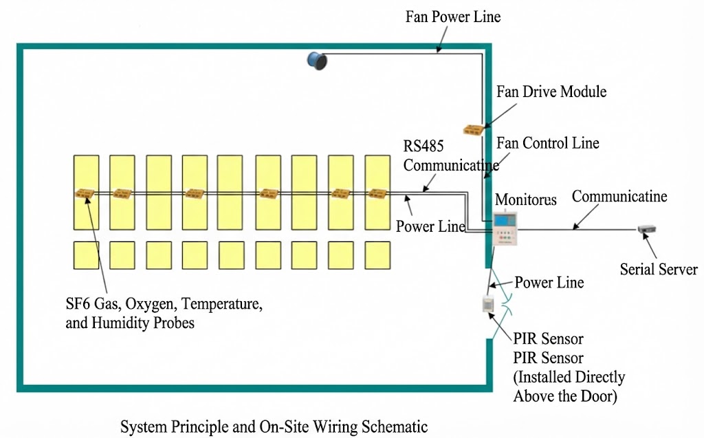
Four-Component System Overview
完全な SF6 gas leak detection and monitoring alarm system integrates four functional subsystems into a unified platform:
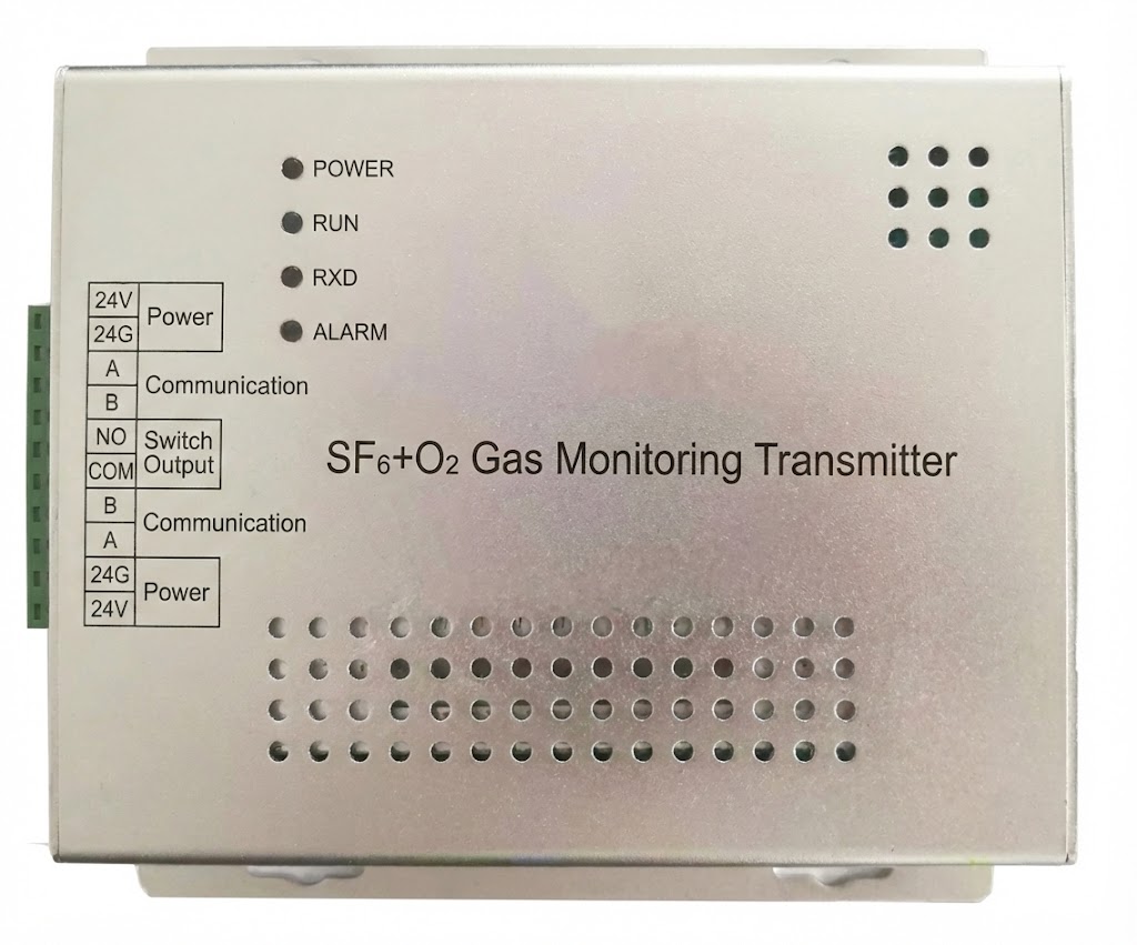
- Four-in-One Transmitter Unit: Field-mounted sensor combining SF6, O2, 温度, and humidity detection in a single compact enclosure
- 監視ホスト: Central controller with touchscreen interface, data processing, コミュニケーション, およびアラーム管理
- Audio-Visual Alarm Devices: Sound, voice, and strobe light indicators for multi-sensory warnings
- LED Large Display (オプション): Remote visualization screen for status monitoring from control rooms or building exteriors
Sensor-Host-Alarm Coordination Mechanism
の four-in-one transmitter continuously samples ambient conditions and converts analog sensor outputs to digital signals. これらの測定値は、 インテリジェント監視ホスト RS485シリアル通信経由 1-5 秒 (設定可能). ホストは測定値をユーザー定義のアラームしきい値と比較します。, データを内部メモリに記録します, タッチスクリーンにリアルタイム値を表示します. SF6が1000ppmを超える場合、または酸素が以下の場合 18%, ホストはただちにアラーム出力をアクティブにします (リレー接点, 聞こえるサイレン, 音声アナウンス) 換気ファンの自動起動をトリガーします. この閉ループ システムは、次の条件で検出から応答までの時間を提供します。 60 秒.
マルチポイント ネットワーキング トポロジ
スケーラブルなネットワーク アーキテクチャ 単一部屋の設置から施設全体の展開までの監視をサポート. 単一のホスト コントローラーで最大で管理できるのは、 8 独立した 検出ポイント, 各トランスミッタには RS485 バス上で一意のアドレスが割り当てられます。. ツイストペアケーブル配線により、デイジーチェーンまたはスタートポロジーでセンサーを接続します, まで伸びる 1200 メートル (4000 足) ホストからの. 大規模な変電所の場合, multiple hosts interconnect via Ethernet TCP/IP, creating hierarchical systems that aggregate data to centralized SCADAプラットフォーム or building management systems. GIS mapping software visualizes all sensor locations, color-coding status (緑=通常, 黄色=警告, 赤=アラーム) for intuitive situational awareness.
9. Four-in-One Gas Detection Sensor
Integrated SF6, O2, 温度, Humidity Design
の four-in-one transmitter consolidates multiple sensing technologies in a 153×150×52mm (6.0×5.9×2.0 inch) aluminum die-cast housing. This integration eliminates the need for separate instruments, reducing installation labor, cabling complexity, and potential failure points. Internal signal conditioning electronics amplify, linearize, and digitize raw sensor outputs, transmitting calibrated engineering units (ppm, %, ℃, %RH) to the host controller.
Installation Positioning: Why Low Mounting?
Optimal sensor placement leverages SF6ガス density characteristics. For 110kV and higher voltage GIS rooms, guidelines specify installation 10cm (4 inches) below finished floor level or within raised floor plenums. The 5× air density causes leaked SF6 to sink and accumulate at the lowest point, where sensor placement ensures earliest possible detection. For 35kV switchgear with wall-mounted circuit breakers, sensors mount 10-15cm above the equipment base, capturing gas before significant room dispersion. Avoid placement near forced air vents, HVAC returns, or doorways where air currents could dilute readings and delay alarm activation.
IP54 Protection and Industrial Environment Adaptation
の IP54 rating (dust protected, splash water resistant) suits harsh substation environments. The enclosure seals against dust ingress that could contaminate sensors or electronics, while gasket seals resist water spray from cleaning or accidental leaks. Operating temperature range of -25°C to +70°C (-13°F ~ +158°F) accommodates unheated equipment rooms in cold climates and tropical installations without air conditioning. For particularly severe environments (coastal salt air, 化学物質への曝露, extreme cold below -25°C), optional heated enclosures maintain sensors at optimal operating temperature.
SF6 Sensor >5 年 耐用年数
Advanced electrochemical SF6 sensors provide exceptional longevity exceeding 5 年間の継続稼働. Stable electrolyte formulations and optimized electrode materials minimize drift, 通常 <±5% per year. This extended lifespan reduces maintenance costs and system downtime compared to earlier-generation sensors requiring annual replacement. 酸素センサー, using consumable lead anodes, typically require replacement after 2-3 years depending on exposure to high oxygen concentrations and temperature cycling. 温度および湿度センサー, based on solid-state RTD and capacitive technologies respectively, often exceed 10-year lifespans with minimal calibration drift.
10. Intelligent Monitoring Host Unit
7-Inch Color Touchscreen Interface
の 監視ホスト features an industrial-grade 7-inch TFT LCD touchscreen with 800×480 pixel resolution and LED backlight for visibility in varying ambient lighting. The intuitive graphical user interface displays all connected sensors simultaneously, with large numeric readouts, colored status indicators, and trend graphs. Menu navigation follows smartphone-like touch gestures, eliminating the need for physical buttons and enabling operation with gloved hands.
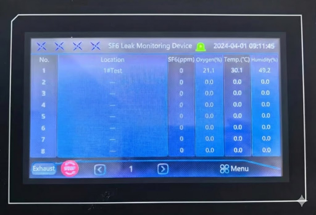
Real-Time Multi-Point Data Display
The main screen presents a live dashboard showing:
- Sensor Identification: User-configurable names (例えば, “GIS Bay 1,” “Control Room,” “Transformer Vault”)
- Current Readings: SF6 concentration (ppm), O2 percentage, 温度 (°C/°F), 湿度 (%RH)
- Status Icons: Green checkmark (普通), yellow triangle (pre-alarm), red exclamation (アラーム)
- System Status: Communication health, power supply voltage, fan relay status
- Time/Date: Synchronized clock for accurate event timestamping
100-Day Historical Data Storage and Query
Non-volatile flash memory stores up to 100 days of continuous measurements at 1-minute intervals (144,000 data points per sensor). Historical query functions allow operators to select date ranges, display trend graphs with zoom/pan, 相関分析のために複数のパラメータをオーバーレイする, and export datasets via USB port. This capability supports incident investigation, コンプライアンス文書, and predictive maintenance by identifying gradual equipment degradation or recurring issues.
RS485/Ethernet Communication Interfaces
Dual communication ports enable flexible system integration:
RS485 Serial Port
Modbus RTU protocol (industry standard) connects to PLCs, RTU, and legacy control systems. Configurable baud rates (9600-115200 bps) and address settings accommodate diverse equipment. Maximum bus length reaches 1200m with proper termination and surge protection.
Ethernet TCP/IP Port
Modbus TCP protocol provides modern network connectivity for SCADA integration, web-based remote access, and building management system (BMS) interfacing. DHCP or static IP addressing, with HTTP server enabling web browser access to real-time data and configuration without proprietary software.
11. Audio-Visual Alarm and Automatic Ventilation System
Sound, Voice, and Strobe Light Triple Alarm
Multi-modal アラーム通知 ensures awareness regardless of environmental conditions or human factors:
- Audible Siren: 85dB @ 1m pulsating tone penetrates background noise and hearing protection
- Voice Announcement: Recorded messages (例えば, “SF6 Gas Alarm, Evacuate Area”) provide clear instruction in multiple languages
- Strobe Light: High-intensity LED beacon (visible 50m+ in daylight) alerts personnel with hearing impairment or wearing earplugs
Alarm escalation follows configurable logic: pre-alarm at 75% of threshold activates strobe only (silent warning), full alarm at 100% threshold activates all outputs, critical alarm at 150% threshold adds emergency contact notification.
6A Relay Automatic Fan Control
The host controller includes 6-amp relay outputs for direct ventilation fan motor control or contactor coil activation (for larger motors). Upon alarm, the relay energizes, starting exhaust fans that purge contaminated air and draw fresh makeup air. Typical switchrooms achieve 10-15 air changes per hour, reducing SF6 concentration below alarm threshold within 10-30 minutes depending on room volume and leak severity.
Manual/Automatic Fan Operation Modes
Operators select control modes via touchscreen:
自動モード
System manages fans based on sensor readings and configured logic. Fans start when SF6 exceeds alarm point or O2 drops below threshold, running until concentrations return to safe levels plus a configurable hold time (通常 15-30 分). This mode ensures optimal air quality with minimal energy consumption.
マニュアルモード
Direct on/off control for maintenance, テスト, or situations requiring continuous ventilation regardless of sensor readings. Manual operation overrides automatic logic but cannot disable alarms, preventing operators from silencing warnings without corrective action.
Infrared Presence Detection Smart Trigger
Passive infrared (PIR) センサー detect human body heat, automatically activating the display backlight and detailed data screens when personnel approach. This energy-saving feature extends LCD lifespan in unmanned facilities while ensuring immediate information availability when operators enter. PIR detection also logs access events, supporting security and maintenance tracking. Some advanced configurations use presence detection to initiate pre-emptive ventilation, ensuring rooms are purged before technicians enter for routine maintenance.
12. LED Large Display Screen (オプション)
Remote Visualization Monitoring Function
The optional LED display panel (68.2×20.2×6.8cm / 26.9×8.0×2.7 inches) mounts in control rooms, security stations, or building exteriors for at-a-glance monitoring without entering hazardous areas. High-brightness LEDs (>2000 nits) remain readable in direct sunlight, ideal for outdoor installations. The display cycles through all monitored locations, showing sensor names and current readings in large characters visible from 20+ メートル.
Outdoor Installation Protection Design
Weatherproof construction includes IP65-rated aluminum enclosure, tempered glass front panel, gasket seals, and drainage channels to prevent water accumulation. Operating temperature range of -30°C to +60°C suits most climates, with optional heating elements for extreme cold. UV-resistant coatings prevent plastic degradation in high-sun locations. The display mounts via keyholes or VESA brackets, with conduit entries for protected wiring.
485 Bus Communication and Data Synchronization
の LEDディスプレイ connects to the monitoring host via the same RS485 network as transmitters, daisy-chaining on the bus and drawing real-time data every 2-5 秒. This architecture eliminates the need for separate PC software or network infrastructure, simplifying deployment. Display behavior (update rate, alarm indication, brightness levels) configures through the host touchscreen or Modbus commands.
13. Real-Time Monitoring and Data Visualization
Simultaneous Multi-Point Status Display
モダンな SF6監視システム present comprehensive facility status on a single screen. Tiled layouts show 4-8 sensor locations with independent readouts, eliminating the need to navigate between pages during critical events. Color-coded backgrounds (緑/黄/赤) provide instant visual assessment of overall safety conditions. Alarm prioritization algorithms highlight the most severe conditions, automatically bringing critical alerts to the foreground.
GIS Map Integration and Visual Monitoring
Geographic Information System (GIS) mapping overlays sensor data onto substation floor plans or facility CAD drawings. Interactive maps display sensor icons at precise installation coordinates, color-coded by status. Clicking an icon reveals detailed readings, 歴史的傾向, and sensor health indicators. This spatial visualization helps operators quickly locate problems in large facilities, understand which equipment areas are affected, and direct maintenance crews efficiently. Some systems integrate with building BIM (Building Information Modeling) databases, linking sensor alarms to equipment asset tags for streamlined work order generation.
ヒストリカルトレンドカーブ分析
Graphical trend displays plot parameters over time, revealing patterns invisible in numeric data. Operators can identify:
- Diurnal Cycles: Temperature/humidity variations correlating with day/night or HVAC schedules
- Gradual Leaks: Slowly rising SF6 baselines indicating chronic seal degradation
- Ventilation Effectiveness: Post-alarm recovery rates validating exhaust fan sizing
- Equipment Issues: Sudden changes coinciding with switching operations or maintenance activities
Zoom, pan, and cursor measurement tools enable detailed examination of specific time periods. Multi-parameter overlay (例えば, SF6 vs. 温度) helps separate actual leaks from density fluctuations due to thermal effects.
14. Intelligent Alarm and Emergency Response
Multi-Level Alarm Threshold Configuration
洗練された アラーム管理 implements three-tier warning system:
Pre-Alarm (警告)
Typically set at 75% of alarm threshold (750ppm SF6 or 18.5% O2). Activates visual indication only (yellow status, no siren), alerting operators to investigate without causing panic or false evacuations. Useful for trending toward alarm conditions during equipment fills or maintenance.
アラーム (Danger)
Standard setpoint (1000ppm SF6 or 18% O2) triggers full audio-visual alarm, voice announcements, and automatic ventilation. Requires immediate response: evacuate non-essential personnel, activate emergency response procedures, investigate and correct source.
High Alarm (致命的)
Advanced warning at 150-200% of alarm threshold (1500-2000ppm SF6 or 16% O2) indicates rapidly deteriorating conditions. Adds emergency notifications (SMS, 電子メール, phone calls to designated contacts), may trigger building-wide evacuation, and logs critical event for incident reporting. Some facilities integrate with fire alarm systems for coordinated response.
Automated Ventilation Interlock Control
Intelligent ventilation control optimizes air quality while minimizing energy consumption. Control logic includes:
- Alarm-Triggered Start: Fans activate immediately when concentration exceeds threshold
- Conditional Run: Fans continue operation until readings drop below 50% of alarm point
- Hold Time: Fans run additional 15-30 minutes after levels normalize to ensure complete purge
- Fail-Safe Operation: System fault or communication loss defaults to continuous fan operation
- Scheduled Purge: Pre-emptive ventilation before entry for maintenance or during high-risk operations
Alarm Records and Event Traceability
Comprehensive event logging captures:
- Timestamp: Precise date/time of alarm activation and clearance (millisecond resolution)
- アラームの種類: Pre/alarm/high, SF6/O2/temperature/humidity parameter
- Peak Values: Maximum concentration reached during event
- 間隔: Time from alarm to return-to-normal
- Operator Actions: Manual acknowledgments, fan starts, threshold adjustments
- System Responses: Automatic ventilation activation, communication attempts
This audit trail supports regulatory compliance (OSHA record-keeping), 事件捜査, trend analysis for predictive maintenance, and continuous improvement of safety procedures.
15. Remote Communication and System Integration
まで 8 Detection Points Networking Support
Scalable architecture accommodates facility growth from single-room monitoring to comprehensive site coverage. それぞれ four-in-one transmitter receives a unique Modbus address (1-247), with a single host managing up to 8 センサー (住所 1-8). RS485 multidrop topology allows sensors at dispersed locations to share a single twisted-pair cable run, dramatically reducing installation costs compared to point-to-point wiring. For facilities exceeding 8 zones, additional hosts deploy at different substations, each managing its own sensor network while interconnecting via Ethernet for centralized oversight.
Modbus RTU/TCP Standard Protocol
Modbusプロトコル universal adoption across industrial automation ensures compatibility with virtually all control systems, データロガー, およびSCADAプラットフォーム:
Modbus RTU (シリアル)
Binary encoding maximizes efficiency on RS485 networks. 一般的な構成: 9600 ボー, 8 データビット, 1 ストップビット, パリティなし (8N1). Supports broadcast commands for simultaneous updates to all devices. Deterministic timing enables reliable operation even with long cable runs or high electromagnetic interference common in substations.
Modbus TCP (イーサネット)
Encapsulates Modbus commands in TCP/IP packets for network communication. Allows connection through standard IT infrastructure (スイッチ, routers, firewalls) without specialized industrial networking hardware. Port 502 (default) or user-configured. TLS encryption available for secure transmission over public networks.
SCADA and BMS System Integration
監視制御とデータ収集 (スカダ) systems aggregate SF6 monitoring into comprehensive facility oversight. Integration delivers:
- Centralized Dashboards: Combine SF6 data with electrical parameters (電圧, 現在, 力), equipment status, weather conditions
- 高度な分析: Machine learning algorithms detect anomalies, 機器の故障を予測する, optimize maintenance schedules
- Automated Responses: Script complex actions (例えば, shed non-critical loads if SF6 alarm during peak demand)
- Historical Data Warehousing: Long-term archival (年) in enterprise databases for regulatory reporting
- モバイルアクセス: Smartphone/tablet apps provide field technicians real-time access to monitoring data
Cloud Platform and Remote Monitoring Capabilities
モダンな IoT-enabled systems upload data to cloud platforms via cellular modems or site internet connections. Cloud solutions provide:
- Multi-Site Monitoring: Utility operators oversee hundreds of substations from central control rooms
- Automatic Reporting: Scheduled generation of compliance reports, maintenance summaries, performance metrics
- Alerting Services: SMS, 電子メール, push notifications to on-call personnel during off-hours
- ソフトウェアのアップデート: Remote firmware upgrades without site visits
- ベンチマーク: Compare performance across similar facilities to identify outliers
16. SF6 Monitoring System Installation Guidelines
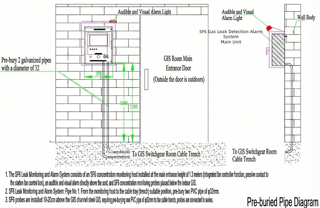
Monitoring Host Installation Requirements
Host mounting location balances accessibility for operators with protection from environmental hazards:
- 位置: Near room entrance (interior or exterior wall) at 1.2-1.5m (4-5 足) eye level for comfortable viewing and touchscreen operation
- Clearances: Minimum 0.3m (12 inches) lateral space for cable routing, 0.5メートル (20 inches) frontal clearance for operator access
- 環境: Avoid direct exposure to rain, 雪, 氷 (even for “屋外” モデル); protect from direct sunlight causing screen glare; maintain ambient temperature within -10°C to +50°C for reliable electronics operation
- 取り付け: Install supplied bracket to wall using appropriate fasteners for substrate (concrete anchors, toggle bolts, wood screws); ensure level mounting for professional appearance and touchscreen accuracy; hang host enclosure on bracket, verify secure engagement
Four-in-One Transmitter Positioning Strategy
最適 センサーの配置 exploits SF6 physics while avoiding false alarms:
High-Voltage GIS Rooms (≥110kV)
Install transmitter 10cm (4 inches) below finished floor or within raised floor plenum. Mount on support bracket anchored to floor slab. Route cable through floor penetration with fire-stop seal. This low placement intercepts sinking SF6 at highest concentrations before room-wide dispersion.
高圧開閉装置 (35kV~66kV)
Wall-mount transmitter 10-15cm above equipment base or at lowest point of room if floor-mounted gear. Avoid placement directly above or below forced ventilation diffusers (minimum 2m / 6ft offset) which could dilute readings.
Common Avoidance Zones
- Air Currents: Not near doors, operable windows, HVAC supplies/returns causing turbulent flow
- Heat Sources: Minimum 1m from transformers, resistors, heaters affecting temperature sensor accuracy
- 障害物: Clear line-of-sight to room volume; avoid behind cable trays, ダクト, or equipment blocking gas diffusion
- 水分: Not in areas subject to standing water, condensation drips, or high-pressure washdown
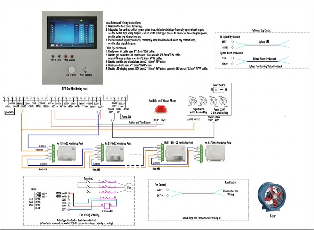
Wiring and Communication Cabling Standards
Electrical installation must meet local codes (NEC, IEC) そしてメーカー仕様書:
Power Wiring
AC/DC 220V ±10%, 50-60Hz supply to host. 使用 14 AWG (2.5mm²) minimum copper wire, protected by 10A circuit breaker. Include ground conductor connected to protective earth. Power entry through bottom/side conduit knockouts (M20, 3/4″ NPT).
RS485 Communication
Twisted-pair cable, 18-22 AWG (0.75-0.5mm²), individually shielded (foil+braid). Maintain twists to connector terminals (don’t untwist more than 10mm). Daisy-chain topology: run cable from host to first transmitter, splice/junction to second transmitter, continue to up to 8th device. Install 120-ohm terminating resistors at each end of bus (typically built into host and last transmitter). Maximum total cable length 1200m; use repeaters for longer runs. Observe polarity: A/+ to A/+, B/- to B/-.
リレー出力 (Fan Control)
Dry contact relay rated 6A @ 250VAC or 6A @ 30VDC. For inductive loads (motor contactors), add snubber circuit (RC network or MOV) to suppress voltage spikes. Use separate power source for controlled device; never backfeed voltage into relay terminals.
System Commissioning and Calibration Process
Systematic startup procedure verifies correct operation before releasing to service:
- Pre-Power Inspection: Visual check of all connections, ケーブルルーティング, 極性, grounds
- Power-Up Sequence: Energize host, verify boot screen, check LCD brightness adjustment
- Communication Test: Confirm host detects all transmitters (sensor count, 住所, signal strength)
- Zero Calibration: In clean air environment (outdoor or well-ventilated room), initiate zero-point calibration for SF6 sensor (sets 0ppm baseline). O2 sensor auto-calibrates to atmospheric 20.9%
- Span Calibration: Apply certified calibration gas (typically 1000ppm SF6 in air balance) to transmitter via calibration hood. Adjust span to match certificate value within ±2% tolerance
- Alarm Verification: Set thresholds to low values temporarily, expose sensor to calibration gas, confirm audio-visual alarms activate, ventilation relay operates
- ドキュメント: Record calibration results, serial numbers, configuration settings in facility maintenance log
17. Daily Maintenance and Sensor Lifespan
Periodic Inspection and Function Checks
Routine メンテナンススケジュール ensures continued reliability:
Monthly Tasks
- 目視検査: 物理的な損傷がないか確認してください, 接続が緩んでいる, 湿気の侵入
- Display Check: Verify touchscreen responsiveness, readability, no pixel failures
- Alarm Test: Use bump test gas to trigger alarm, confirm siren, strobe, voice, ventilation activation
- Sensor Cleaning: Gently wipe transmitter sensor ports with dry cloth to remove dust accumulation (do not use compressed air or solvents)
Quarterly Tasks
- Data Download: Export historical logs via USB, archive to facility records
- バッテリーバックアップ: If system includes UPS, verify battery charge, runtime test
- Ventilation Test: Manually activate fans, listen for abnormal noise, verify airflow with anemometer
- Communication Test: Check SCADA/BMS data flow, confirm remote access functionality
Annual SF6 Sensor Calibration Requirements
SF6 sensor recalibration compensates for normal electrochemical drift:
- Schedule: Perform every 12 months from installation date or more frequently if operating in harsh conditions (高温, 湿度, 汚染)
- Certified Gas: Use NIST-traceable calibration cylinder (1000ppm SF6 ±2% in air balance) with current certificate of analysis
- Procedure: Access calibration menu via touchscreen or Modbus commands. Attach gas cylinder with regulator to calibration hood over transmitter. Flow gas at 0.5-1.0 LPM for 2-3 minutes until reading stabilizes. Adjust sensor span so displayed value matches cylinder certificate. Remove calibration gas, verify return to 0ppm in clean air
- ドキュメント: Record pre/post calibration readings, gas cylinder lot number, technician name, date in maintenance log. Affix calibration sticker to transmitter with next due date
Oxygen Sensor Replacement Interval
電気化学的酸素センサー have finite lifespans due to consumable anode material:
- Typical Life: 24-36 months continuous operation in normal conditions (15-25℃, 20-80% RH)
- Replacement Indicators: Excessive drift (>1% per week), erratic readings, failure to zero-calibrate, physical damage to membrane
- Procedure: Power down transmitter (or use hot-swap capable models). Unscrew sensor retaining ring. Remove old sensor, note orientation key. Install new sensor ensuring proper seating and O-ring seal. Power up, allow 30-minute warm-up, perform zero calibration in fresh air (20.9% O2)
- Disposal: Spent O2 sensors contain lead; dispose as electronic waste per local regulations, not general trash
Troubleshooting Common Faults
Systematic 故障診断 resolves most issues:
| 症状 | Possible Cause | 解決 |
|---|---|---|
| Transmitter offline | Communication cable fault, address conflict, power loss | Check cable continuity, verify unique addresses, confirm 24VDC at transmitter terminals |
| Erratic SF6 readings | Sensor contamination, 温度変動, EMI | Clean sensor, シールドケーブル, relocate away from interference sources |
| Alarm won’t silence | Actual gas present, threshold set too low, sensor fault | Verify with portable instrument, adjust setpoint, replace sensor if defective |
| Fan won’t start | Relay failure, motor contactor issue, wiring error | Test relay with multimeter, verify 220V at contactor, check interlock permissives |
| Touchscreen unresponsive | 校正ドリフト, firmware hang, hardware failure | Perform touchscreen re-calibration, power cycle host, contact manufacturer if persistent |
18. Power Utility Application Cases
China State Grid 220kV Substation Network
プロジェクトの範囲: Deployment of 150+ SF6 gas leak detection systems across provincial power grid substations covering 110kV to 500kV voltage classes.
Technical Implementation: Each substation features 4-8 four-in-one transmitters monitoring GIS bays, circuit breaker rooms, and SF6 storage areas. Central monitoring hosts connect to provincial grid SCADA via fiber optic Ethernet, providing real-time visibility to control center operators 24/7.
Measurable Results:
- Zero Personnel Injuries: No SF6 exposure incidents since system installation (2018-present)
- 40% Reduction in Emergency Responses: Early leak detection enables scheduled maintenance instead of after-hours callouts
- Complete Regulatory Compliance: Continuous monitoring exceeds State Grid safety requirements, documented for annual audits
- Quantified Leak Reduction: System identified 23 chronic leaks (slow seal degradation), repairs prevented estimated 500kg SF6 emissions
USA California Utility Smart Grid Initiative
プロジェクトの範囲: Grid modernization program covering 200+ distribution and transmission substations serving 1.5 million customers across Northern California.
Technical Implementation: SF6監視システム integrate with smart grid infrastructure through IEC 61850 プロトコル. Cloud-based analytics platform aggregates data from all sites, applying machine learning to detect abnormal patterns indicative of equipment degradation before catastrophic failures occur.
Measurable Results:
- 45% Reduction in Equipment Failures: Predictive analytics identified 87 circuit breakers requiring preventive maintenance
- $2.3M Annual Savings: Avoided equipment damage, サービスの中断, and overtime labor
- Environmental Leadership: Published SF6 emissions inventory showing 15% reduction year-over-year, recognized by EPA
- システムの信頼性の向上: サイト (システムの平均中断時間インデックス) improved by 8% attributed partially to proactive SF6 management
Germany Renewable Energy Wind Farm Network
プロジェクトの範囲: SF6ガス監視 横切って 25 wind farm collector substations, integrating onshore and offshore renewable generation into the national grid.
Technical Implementation: Remote unmanned substations required autonomous operation in harsh coastal environments. Systems specified with IP65 outdoor-rated enclosures, heated sensor housings for sub-zero operation, and cellular M2M connectivity for remote access. Solar+battery backup ensures monitoring continuity during grid outages.
Measurable Results:
- Offshore Reliability: 99.7% uptime in salt spray, 高湿度, 極端な温度 (-15°C ~ +40°C)
- 規制の遵守: Real-time emissions reporting to environmental agencies via API integration
- メンテナンスの最適化: Remote diagnostics reduced site visits by 60%, critical for offshore platforms with helicopter access
- 漏れの検出: System identified corroded seal in offshore platform, preventing 50kg SF6 release into marine environment
19. Rail Transit Application Cases
India Mumbai Metro Rail Project
プロジェクトの範囲: のインストール 45 SF6 leak detection and monitoring systems across metro line electrical substations and traction power facilities serving 3 million daily passengers.
Technical Implementation: Compact urban environment required space-efficient solutions. Four-in-one transmitters mounted in equipment cabinets alongside switchgear, with LED displays visible to platform supervisors. Hindi/English bilingual interface accommodates diverse workforce. Integration with metro operations control center (OCC) enables centralized safety oversight.
Measurable Results:
- Zero Service Disruptions: Proactive leak detection prevented SF6-related equipment failures during 5-year operational period
- Worker Safety Excellence: No confined-space incidents in maintenance crews, exceeding national railway safety benchmarks
- Compliance Achievement: Fulfilled Delhi Metro Rail Corporation (DMRC) technical specifications for environmental and safety monitoring
- 知識の伝達: Trained 120 metro technicians on SF6 handling and monitoring, improving overall system safety culture
UK London Underground Transportation Authority
プロジェクトの範囲: Safety monitoring for 40+ underground electrical substations in the world’s oldest metro system, some dating to 1890s infrastructure.
Technical Implementation: Retrofitting SF6 monitoring into historic confined-space installations required custom sensor mounting brackets and explosion-proof certifications for areas with potential methane accumulation. RS485 networks leveraged existing signal cables in conduits, avoiding costly excavation. WiFi mesh repeaters extended Ethernet connectivity through tunnels to central control.
Measurable Results:
- Heritage Protection: Non-invasive installation preserved historic infrastructure while achieving modern safety standards
- 24/7 遠隔監視: Control room operators oversee all substations from central location, dispatching maintenance crews only when necessary
- インシデント対応: 60% faster emergency response due to precise alarm location information and automated notification
- Regulatory Approval: System met stringent Health and Safety Executive (HSE) requirements for confined-space entry permits
20. Data Center and Critical Infrastructure
Singapore Marina Bay Financial District Data Centers
プロジェクトの範囲: 包括的な SF6ガス監視 で 8 Tier III+ colocation data centers with 24/7 uptime requirements serving banking, finance, and cloud service providers.
Technical Implementation: 冗長性 監視システム with dual hosts and power supplies ensure no single point of failure. Integration with building management system (BMS) links SF6 alarms to fire suppression, 空調設備, and access control. Automated reporting generates monthly compliance documents for SOC 2 audits and customer SLA verification.
Measurable Results:
- 99.999% システムの可用性: Five-nines reliability maintained across electrical infrastructure supporting mission-critical IT loads
- 15% Cooling Cost Reduction: Optimized ventilation based on real-time temperature/humidity data, reducing CRAC unit runtime
- Certified Reliability: Contributed to Uptime Institute Tier III certification demonstrating 72-hour self-sufficiency
- 顧客の信頼: Transparent safety monitoring documented in facility tours, supporting premium pricing for colocation space
UAE Dubai International Airport Electrical Infrastructure
プロジェクトの範囲: Critical power monitoring covering 30+ switchgear rooms and substations supporting runways, 端子, baggage handling, and air traffic control at world’s busiest international airport.
Technical Implementation: SF6 leak detection systems integrate with airport-wide safety infrastructure including fire alarm, security access, and operations control. Arabic/English interfaces comply with UAE regulatory requirements. Explosion-proof ratings meet aviation safety standards for areas near jet fuel operations.
Measurable Results:
- Zero Airport Closures: Prevented electrical equipment failures that could ground flights or disrupt operations
- ICAO Compliance: International Civil Aviation Organization safety audit commended monitoring systems
- 経済的影響: Avoided estimated $5M per hour revenue loss from potential power disruptions
- Security Integration: SF6 alarm events cross-referenced with access logs to identify maintenance errors or unauthorized entry
Australia Sydney Opera House & Landmark Infrastructure
プロジェクトの範囲: Heritage site electrical monitoring with stringent aesthetic integration requirements for UNESCO World Heritage protection.
Technical Implementation: Concealed installations with sensors in existing electrical vaults, junction boxes camouflaged in architectural elements, and hosts in back-of-house technical spaces invisible to public. Low-voltage DC wiring eliminated need for conduit expansion that would damage historic fabric. Wireless communication reduced cable routing through protected spaces.
Measurable Results:
- Heritage Preservation: Zero permanent alterations to Jørn Utzon’s iconic architecture
- Tourist Safety: Protects 8.2 million annual visitors from electrical infrastructure hazards
- Operational Excellence: 99.2% facility uptime for 1500+ annual performances despite aging (1973) 電気システム
- Cultural Stewardship: Monitoring demonstrates proactive conservation, supporting continued UNESCO designation
21. SF6 Monitoring System Technical Specifications
Complete System Parameters
| パラメータ | 仕様 |
|---|---|
| 電源 | AC/DC 220V ±10%, 50-60Hz universal |
| 消費電力 | Standby <10W, アラーム <15W (energy efficient) |
| 精度クラス | クラス 5 (industrial grade) |
| SF6 Gas Detection | |
| 検知範囲 | 0-3000ppm (0-0.3% volume) |
| 正確さ | ±2% Full Scale (±60ppm @ 3000ppm) |
| アラームしきい値 | 1000ppm (国家標準), user adjustable |
| 応答時間 | T90 <30 秒 |
| Sensor Lifespan | >5 years continuous operation |
| Oxygen Monitoring | |
| 検知範囲 | 0-25% volume concentration |
| 正確さ | ±1% Full Scale (±0.25% @ 25%) |
| アラームしきい値 | 18% (OSHA/national standard), 調整可能な |
| センサー技術 | Electrochemical lead-anode cell |
| Sensor Lifespan | 24-36 months typical |
| 温度監視 | |
| 測定範囲 | -30°C to +99°C (-22°F to +210°F) |
| 正確さ | ±0.5℃ (±0.9°F) |
| センサーの種類 | プラチナ測温抵抗体 (Pt1000) |
| 湿度監視 | |
| 測定範囲 | 10-99% 相対湿度 |
| 正確さ | ±3% RH (±0.3% absolute) |
| センサーの種類 | Capacitive polymer thin-film |
| Control Outputs | |
| Fan Control Relay | 6A @ 250VAC / 6A @ 30VDC (SPDT) |
| Alarm Relay | 3A @ 250VAC / 3A @ 30VDC (SPDT) |
| 通信インターフェース | |
| RS485 Serial | Modbus RTU, 9600-115200 ボー, 1200mまで |
| イーサネット | 10/100 Mbps, Modbus TCP, HTTP web server |
| Maximum Sensors | 8 transmitters per host (expandable via multiple hosts) |
| ユーザーインターフェース | |
| 表示タイプ | 7-インチカラーTFT LCDタッチスクリーン |
| 解決 | 800×480ピクセル (WVGA) |
| バックライト | 導かれた, 自動調光, >50,000 時間寿命 |
| データストレージ | |
| メモリ容量 | 100 1分間隔で数日間連続録画 |
| データ形式 | USB ポートまたはイーサネット ダウンロード経由での CSV エクスポート |
| 物理的寸法 | |
| 監視ホスト | 300×400×81mm (11.8×15.7×3.2インチ) |
| フォーインワン送信機 | 153×150×52mm (6.0×5.9×2.0インチ) |
| LEDディスプレイ (オプション) | 682×202×68mm (26.9×8.0×2.7 inches) |
| 環境評価 | |
| 動作温度 | -25°C ~ +70°C (-13°F ~ +158°F) |
| 保管温度 | -40°C ~ +85°C (-40°F ~ +185°F) |
| 動作湿度 | ≤95% RH non-condensing |
| 侵入保護 | IP54 (送信機), IP40 (屋内ホスト) |
| インストール | |
| 取り付け | 壁掛け (付属のブラケット) |
| ケーブル入口 | M20 / 3/4″ NPT 導管ノックアウト |
22. Compliance with International Standards
製品認証
私たちの SF6 ガス漏れ検知および監視システム 世界的な安全性への準拠を証明する以下の認定を取得しています, 品質, および環境基準:
CEマーキング (欧州適合性)
EU 低電圧指令への適合を認証 (LVD) 2014/35/電気安全に関する EU, 電磁適合性 (EMC) イミュニティおよび排出に関する指令 2014/30/EU, および有害物質の制限 (RoHS) 環境保護に関する指令 2011/65/EU. CE マーキングにより、欧州経済領域全体での自由貿易が可能になります.
GB/T Chinese National Standards
Compliance with GB/T 11022 (高圧開閉装置), GB 3836 (爆発性雰囲気), and GB/T 17626 (EMC immunity) series ensures suitability for China State Grid and provincial utility deployments.
IEC国際規格
- IEC 61850: 電力事業自動化のための通信ネットワークとシステム, enabling interoperability with SCADA and substation automation systems worldwide
- IEC 60068: 環境試験 (温度, 湿度, 振動, ショック) validates reliability in harsh substation environments
- IEC 61010: Safety requirements for electrical equipment for measurement, コントロール, and laboratory use
Workplace Safety Regulations
オシャ (労働安全衛生管理)
System design addresses OSHA standards including:
- 29 CFR 1910.146: Permit-required confined spaces – continuous atmospheric monitoring before and during entry
- 29 CFR 1910.134: Respiratory protection – alarm thresholds trigger supplied-air respirator requirements
- 29 CFR 1910.1200: Hazard communication – MSDS/SDS documentation for SF6 gas handling
EPA (Environmental Protection Agency)
Supports compliance with EPA SF6 Emission Reduction Partnership for Electric Power Systems, including annual emissions inventory reporting (Form 3-1), leak detection and repair programs, and voluntary reduction targets. Continuous monitoring provides accurate leak quantification data for regulatory submissions.
Industry Application Standards
IEEE (Institute of Electrical and Electronics Engineers)
- IEEE C37.122: Gas-insulated substations rated above 52kV – specifies SF6 monitoring requirements
- IEEE C37.85: Qualifying class 1E protective relays – ensures monitoring system reliability for nuclear safety applications
シグル (International Council on Large Electric Systems)
Recommendations from CIGRE working groups on SF6 handling (WG B3.02) そして資産管理 (WG C1.1) inform system design for utility best practices including leak rate calculation methodologies and acceptance criteria.
23. よくある質問 (よくある質問)
What is sulfur hexafluoride used for?
六フッ化硫黄 (SF6) serves primarily as an electrical insulation and arc-quenching medium in high-voltage equipment including gas-insulated switchgear (GIS), サーキットブレーカー, 変圧器, and transmission lines rated from 36kV to 800kV. SF6’s superior dielectric strength (2.5×空気) enables compact equipment designs. Secondary applications include medical ultrasound contrast agents (SF6 microspheres), semiconductor etching, magnesium casting cover gas, and laboratory tracer studies.
Is sulfur hexafluoride safe?
SF6 gas is non-toxic and chemically inert under normal conditions, posing no direct poisoning risk. しかし, SF6 presents serious asphyxiation hazard due to its high density (5×空気). In confined spaces, leaked SF6 displaces oxygen, creating oxygen-deficient atmospheres that can cause unconsciousness and death without warning odor or irritation. さらに, SF6 decomposition products from electrical arcing (二酸化硫黄, フッ化水素, metal fluorides) are toxic and corrosive. Proper monitoring, 換気, and respiratory protection are essential for safe handling.
How many rooms can the system monitor simultaneously?
シングル 監視ホスト までサポートします 8 independent detection points (rooms, zones, or equipment areas) via RS485 multi-drop network. Each point requires one four-in-one transmitter. For larger facilities, deploy multiple hosts interconnected via Ethernet, creating scalable architecture monitoring dozens to hundreds of locations. Cloud-based platforms aggregate data from all hosts for centralized multi-site oversight.
Will data be lost during power outages?
いいえ. システムが使用するのは、 non-volatile flash memory that retains all historical data, configuration settings, and alarm thresholds during power loss. Upon restoration, the system automatically resumes operation with no data loss or reconfiguration needed. For critical applications requiring uninterrupted monitoring during outages, optional UPS (uninterruptible power supply) backup maintains full functionality for 4-8 hours depending on battery capacity.
Can the system integrate with existing control systems?
はい. Standard Modbus RTU/TCP protocols ensure compatibility with virtually all industrial control systems including SCADA (監視制御とデータ収集), DCS (分散制御システム), PLC (プログラマブル ロジック コントローラー), and BMS (ビル管理システム). The system maps sensor readings, アラーム状態, and relay outputs to Modbus registers accessible by master devices. We provide protocol documentation and technical support for integration. Custom protocols (OPC-UA, BACネット, DNP3) available upon request.
How often do sensors require calibration?
SF6 sensors: Annual calibration recommended using NIST-traceable certified gas to maintain ±2% accuracy specification. More frequent calibration (quarterly or semi-annual) may be necessary in harsh environments with temperature extremes, 高湿度, or contamination exposure.
酸素センサー: Calibrate every 6-12 months or whenever readings drift beyond ±1% tolerance. Zero-calibration in fresh air (20.9% O2) is simple field procedure; span calibration requires certified gas mixture.
Temperature/humidity sensors: Factory calibrated with typical drift <0.1°C/year and <1% RH/year, requiring recalibration only every 2-3 years unless accuracy degradation observed.
What warranty and support is provided?
福州イノベーション電子科学&テック株式会社, 株式会社. 提供します:
- 標準保証: 24 months from installation date covering materials and workmanship defects
- Extended Warranty: オプション 3-5 year plans available at purchase
- テクニカルサポート: 電子メール, 電話, WhatsApp assistance during business hours (GMT+8 timezone). Remote system access for diagnostics
- スペアパーツ: Stocked sensors, relay modules, cables for rapid replacement shipping
- 校正サービス: On-site or return-to-factory calibration with certificate traceable to national standards
- トレーニング: インストール, 手術, and maintenance training via video conference or on-site visits
- 予防保守: Annual service contracts include calibration, 検査, parts replacement, and priority support
Does the system comply with North American electrical codes?
While our equipment primarily targets international markets and complies with IEC standards, many specifications align with North American requirements. For UL/CSA certification or NEC/CEC compliance verification needed for U.S./Canada installations, consult our technical team regarding available options. We have successfully deployed systems in North American facilities where IEC equivalency was accepted by authorities having jurisdiction (AHJ).
24. Selecting the Right SF6 Monitoring Solution
Assessing Your Facility Monitoring Requirements
効果的 SF6 gas leak detection begins with thorough needs assessment:
- Inventory SF6 Equipment: Identify all circuit breakers, 開閉装置, 変圧器, and other devices containing SF6 gas
- Map Enclosed Spaces: Document switchrooms, vaults, ケーブルトンネル, and confined areas requiring monitoring
- Evaluate Risk Factors: Consider equipment age/condition, メンテナンス履歴, confined space access frequency, worker exposure duration
- Determine Coverage: Calculate number of detection points needed (通常 1 transmitter per 50-100 m² depending on room geometry)
- 統合要件: Identify existing control systems, 通信プロトコル, and IT infrastructure for seamless integration
System Reliability and Future Expansion
Invest in scalable solutions that grow with your facility:
- Modular Architecture: Systems supporting multi-point expansion avoid costly replacements when adding monitored areas
- Open Protocols: Modbus RTU/TCP ensures compatibility with future control system upgrades or replacements
- Long Sensor Life: >5 year SF6 sensor lifespan and >2 year O2 sensor life reduce ongoing maintenance burden
- ファームウェアのアップデート: Remote update capability adds new features and addresses issues without hardware changes
- Manufacturer Stability: Partner with established manufacturers (Fuzhou INNO since 2011) ensuring long-term parts availability and support
総所有コストの分析
評価する lifecycle costs beyond initial purchase price:
| コストカテゴリ | 考慮事項 |
|---|---|
| 装置 | Host, 送信機, ディスプレイ, ケーブル, 取り付け金具 |
| 取り付け作業 | Electrician time, 導管, ワイヤー, 試運転, トレーニング |
| Annual Calibration | Calibration gas, technician time or service contract |
| Sensor Replacement | O2 sensors every 2-3 年, SF6 sensors every 5+ 年 |
| エネルギー消費量 | <10W standby power = negligible operating cost |
| Avoided Costs | Prevented injuries, 機器の損傷, environmental fines, ダウンタイム |
Comprehensive systems typically achieve payback within 2-4 years through reduced incidents, 最適化されたメンテナンス, and regulatory compliance cost avoidance.
連絡先
For technical consultation, quotation requests, or customized monitoring solutions, 接触:
福州イノベーション電子科学&テック株式会社, 株式会社.
設立: 2011
専門分野: 光ファイバー温度センサー, gas detection systems, 変圧器の監視
Contact Details:
電子メール: web@fjinno.net
WhatsApp/WeChat/電話: +86 135 9907 0393
QQ: 3408968340
Webサイト: www.fjinno.net
Factory Address:
連東U穀物ネットワーキング工業団地
いいえ. 12 興業西路
福州, 福建省
People’s Republic of China
私たちは提供します:
- Free technical consultation and application engineering support
- Custom system design for unique facility requirements
- Competitive pricing for volume projects and OEM partnerships
- Global shipping and international technical support
- Comprehensive documentation in English and multiple languages
免責事項
General Information: This article provides general information about sulfur hexafluoride (SF6) gas and monitoring systems for educational purposes. 正確性を追求する一方で、, information is subject to change without notice. Always consult current product datasheets, 現地の規制, and qualified professionals before making procurement or installation decisions.
技術仕様: All specifications, 寸法, パフォーマンスデータ, and capabilities described are subject to change as part of continuous product improvement. Actual products may vary slightly from published specifications. クリティカルなアプリケーション向け, verify current specifications with our technical team before purchase.
専門家の取り付けが必要です: SF6 gas detection systems must be installed by qualified electricians and instrumentation technicians in accordance with local electrical codes, manufacturer instructions, and workplace safety regulations. Improper installation can result in equipment damage, inaccurate readings, または安全上の危険.
Safety Critical Application: While our monitoring systems enhance workplace safety, they do not eliminate all risks associated with SF6 gas. Employers remain responsible for comprehensive safety programs including proper training, 換気, confined space procedures, respiratory protection, and emergency response planning. Monitoring systems supplement, but do not replace, proper safety practices.
No Warranty of Fitness: Information provided does not constitute a warranty that products are suitable for any particular purpose or application. Users must independently verify system appropriateness for their specific requirements, 環境条件, and regulatory obligations.
責任の制限: 福州イノベーション電子科学&テック株式会社, 株式会社, its employees, and representatives shall not be liable for any direct, 間接的な, 偶発, 結果的な, or punitive damages arising from use or misuse of information in this article or products described herein. Maximum liability is limited to the purchase price of equipment.
規制の遵守: Users are solely responsible for ensuring installations comply with all applicable local, national, and international regulations including but not limited to electrical codes (NEC, IEC), workplace safety standards (オシャ, HSE), and environmental regulations (EPA, EU F-Gas). This article does not constitute legal or regulatory advice.
Third-Party Information: サードパーティ製品への言及, standards organizations, ケーススタディ, or external sources are provided for information only and do not imply endorsement. We are not responsible for accuracy of third-party information or continued availability of external resources.
Intellectual Property: 製品名, 商標, and logos mentioned belong to their respective owners. Use does not imply affiliation or endorsement. Content © 2011-2026 福州イノベーション電子科学&テック株式会社, 株式会社. 無断転載を禁じます.
最終更新日: February 2026

光ファイバー温度センサー, インテリジェント監視システム, 中国の分散型光ファイバーメーカー
 |
 |
 |