 INNO光ファイバー温度センサー ,温度監視システム.
- 開閉装置の過熱は、電気火災や産業施設や公共施設の計画外停止の主な原因です.
- ザ 3 開閉装置の温度を監視する実証済みの方法は次のとおりです。: 蛍光ファイバー光センシング, ワイヤレス温度センサー, そして 赤外線サーモグラフィー.
- 蛍光光ファイバーシステム 継続的に提供する, 高精度測定を実現し、高圧開閉装置のゴールドスタンダードです.
- ワイヤレス温度監視センサー 工具不要の設置とリアルタイムのマルチポイント カバレッジを提供 - 既存のスイッチルームの改修に最適.
- 赤外線サーマルカメラ 視覚的なヒート マッピングを提供し、メンテナンス チームによる定期検査に最適です。.
- オンライン監視と定期的な赤外線検査を組み合わせることで、開閉装置資産を最も包括的に保護します。.
- 適切な温度監視により機器の寿命が延びます, メンテナンスコストを削減, 致命的な障害が発生する前に防止します.
1. 開閉装置とは? The Core of Every Power Distribution System

Switchgear refers to a combination of electrical disconnect switches, ヒューズ, and circuit breakers used to control, 守る, and isolate electrical equipment in power distribution networks. Found in virtually every large facility — from manufacturing plants and data centers to hospitals and substations — switchgear is the critical junction between incoming power supply and downstream loads.
Common Types of Switchgear
Switchgear is broadly categorized by voltage level and design. 高圧開閉装置 (above 36kV) handles transmission-level electricity, その間 高圧開閉装置 (1kV–36kV) is widely used in industrial distribution. Low-voltage switchgear (below 1kV) manages final distribution to equipment and machinery. Specialized forms include リング本体 (RMU), ガス絶縁開閉装置 (地理情報システム), そして metal-clad switchgear panels.
Industries That Depend on Switchgear
Reliable switchgear operation is mission-critical across sectors including oil and gas, 公共事業, 鉄道輸送, commercial real estate, 半導体製造, とヘルスケア. Any thermal failure in these environments carries significant safety, 金融, and operational consequences.
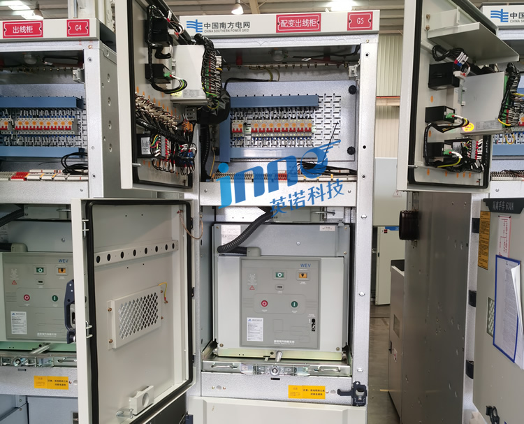
2. Inside the Cabinet: Key Components of Electrical Switchgear

Understanding switchgear construction is essential for identifying where temperature monitoring is most needed. 典型的な medium-voltage switchgear panel contains the following core components:
主なコンポーネント
- サーキットブレーカー — Interrupt fault currents; moving contacts generate heat under load.
- バスバー — Copper or aluminum conductors that distribute current throughout the cabinet; connection joints are high-risk thermal points.
- 変流器 (CT) — Measure current flow; windings are susceptible to insulation degradation from heat.
- 断路器 / Isolating Switches — Provide safe isolation; contact arms can develop high resistance over time.
- Cable Terminations and Connectors — Loose or oxidized connections are among the most common sources of abnormal heating.
- Secondary Control Circuits — Terminal blocks and wiring within control compartments can overheat due to poor connections or overload.
Each of these components operates under continuous electrical stress. それなし real-time switchgear temperature monitoring, degradation is invisible until a fault occurs.
3. Why Does Switchgear Fail? Root Causes of Electrical Cabinet Faults
Switchgear failure rarely happens without warning — but the warning signs are often thermal. Industry data consistently shows that overheating accounts for over 30% of all switchgear-related failures, making it the single most common fault category.
Primary Causes of Switchgear Overheating
接触抵抗の増加
Loose bolted connections, oxidized busbar joints, and worn circuit breaker contacts all raise contact resistance. According to Joule’s Law, even a small increase in resistance generates disproportionately more heat under load — a problem that compounds over time if undetected.
Sustained Overload Conditions
Running switchgear above its rated current capacity causes conductors and insulation to exceed design temperatures. This is especially common in aging facilities where load growth has outpaced infrastructure upgrades.
Inadequate Ventilation and Cooling
Blocked ventilation slots, high ambient temperatures, or improper cabinet spacing prevent effective heat dissipation. Switchrooms in tropical climates or poorly ventilated basements are particularly vulnerable.
Installation and Commissioning Defects
Under-torqued bus connections, incorrect cable sizing, and poor termination workmanship introduce resistance at the point of installation — faults that may not manifest for months or years.
水分, 汚染, and Corrosion
結露, dust ingress, and chemical exposure degrade insulation and increase surface leakage currents, both of which contribute to abnormal heating patterns.
4. The Hidden Danger: What Risks Does Switchgear Overheating Create?
Thermal degradation inside a power distribution cabinet is not merely an equipment issue — it is a safety, 金融, and operational risk that affects entire facilities.
加速された絶縁劣化
The Arrhenius Rule, widely applied in electrical engineering, states that for every 10°C rise above rated operating temperature, insulation life is effectively halved. A switchgear panel running 20°C above its design temperature will age four times faster than intended.
Arc Flash and Electrical Fire
アークフラッシュ事件 in switchgear are frequently triggered by thermally weakened insulation. The energy released in an arc flash event can cause severe burns, 設備破壊, and structural fire — with blast pressures exceeding those of many industrial explosives. Early-stage thermal detection is one of the most effective arc flash prevention strategies available.
Unplanned Downtime and Production Loss
A single switchgear failure can shut down an entire production line, data center floor, or hospital wing. Downtime costs in heavy industry routinely exceed tens of thousands of dollars per hour. Continuous switchgear monitoring 状態ベースのメンテナンスを可能にする, replacing reactive repair with planned intervention.
Personnel Safety Hazards
Maintenance technicians working on or near overheated switchgear face direct exposure to thermal burns, toxic fumes from degrading insulation, and the risk of arc flash. 積極的 switchgear thermal management directly reduces the frequency of hazardous work conditions.
Regulatory and Insurance Consequences
Many jurisdictions require documented evidence of thermal inspection for electrical equipment. Failure to maintain adequate temperature monitoring records can void equipment warranties, invalidate insurance claims, and result in regulatory penalties following an incident.
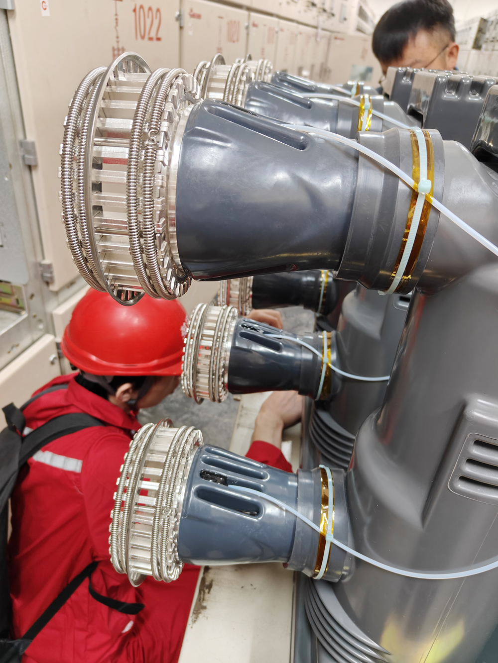
5. Where Does Heat Build Up? Critical Hotspot Locations in Power Switchgear

効果的 開閉装置のホットスポット検出 requires knowing exactly where thermal stress concentrates. The following locations account for the majority of temperature-related faults in medium and high-voltage electrical cabinets:
バスバージョイントと接続ポイント
バスバー接続 are the most frequently cited thermal fault location in switchgear. Bolted joints that loosen over time — due to thermal cycling, 振動, or initial under-torquing — develop elevated contact resistance and generate localized hot spots that can reach dangerous levels within weeks.
Circuit Breaker Moving and Static Contacts
The contact interface inside a vacuum circuit breaker or air circuit breaker carries full load current. 接点の摩耗, 位置ずれ, or spring fatigue increases transition resistance, causing concentrated heating at the point of current transfer.
Cable Terminations and Lug Connections
Poorly crimped lugs, under-tightened terminal bolts, and oxidized aluminum-to-copper interfaces are among the most common sources of thermal faults in low and medium-voltage switchboards. These faults are deceptive — they often appear normal visually but register significant heat signatures under load.
Isolating Switch Contact Arms
The sliding or rolling contacts of disconnector switches experience mechanical wear with each operation cycle. As contact pressure decreases, resistance — and heat — increases proportionally.
Current Transformer Windings
Overloaded or incorrectly rated 変流器 can experience internal winding heating, which is difficult to detect without embedded sensors or thermographic inspection.
Secondary Terminal Blocks
Within the low-voltage control compartment, terminal strip connections carrying relay and metering circuits can overheat due to loose wiring, incorrect fuse sizing, or short-circuit conditions in control circuits.
6. 3 Best Switchgear Temperature Monitoring Methods Compared
右を選択する 開閉装置温度監視システム depends on voltage level, 設置条件, 予算, および運用要件. Below is a detailed breakdown of each method and a direct comparison.
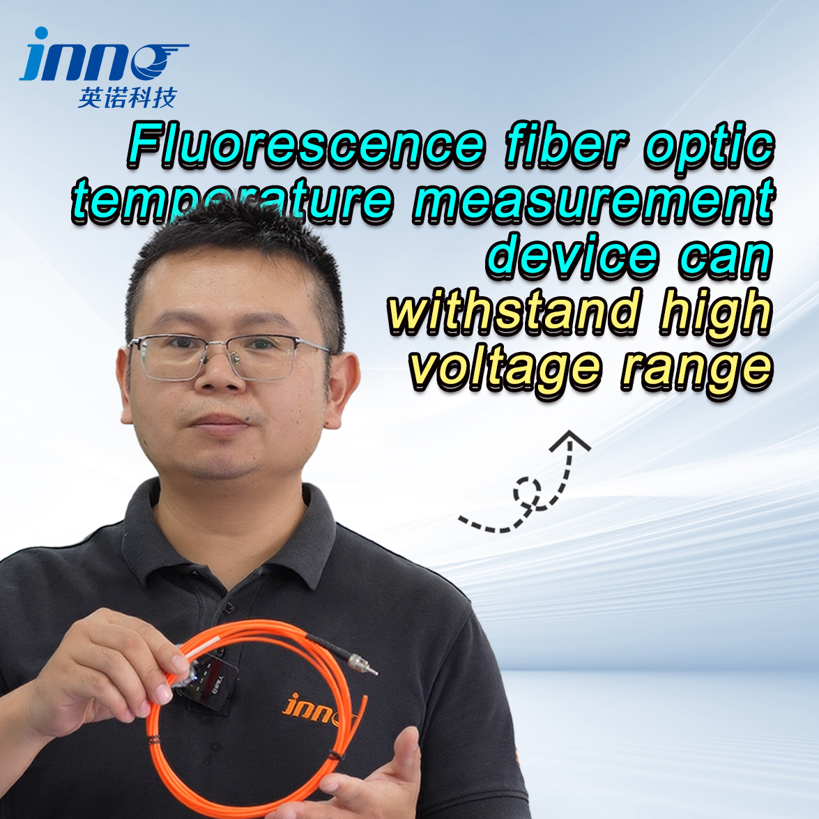
方法 1: 蛍光光ファイバー温度検知

蛍光光ファイバー温度センサー — also known as 光ファイバー温度測定システム — operate by measuring the fluorescence decay time of a rare-earth compound attached to the fiber tip. This decay rate changes predictably with temperature, enabling accurate measurement that is completely independent of electrical interference.
主な利点
- 本質安全防爆 — no electrical components at the sensing point; fully passive and immune to high-voltage fields
- Measurement accuracy of ±0.5°C to ±1°C — the highest precision available for embedded switchgear monitoring
- 電磁干渉に対する耐性 (EMIの), 無線周波数干渉 (情報提供依頼), and lightning transients
- Suitable for direct contact measurement on 10kV, 35kV, and GIS switchgear busbars and contacts
- サポート 24/7 continuous online monitoring with multi-channel demodulators
- Long service life with no battery replacement required
方法 2: Wireless Temperature Monitoring Sensors
Wireless switchgear temperature sensors use battery-powered transmitter nodes to collect temperature data at defined measurement points and relay it to a central receiver or cloud platform via protocols such as ジグビー, ロラ, or 2.4GHz RF. This architecture eliminates the need for signal cabling entirely.
主な利点
- Tool-free installation — no cabling, no panel modification, 最小限のダウンタイム
- Scalable mesh network supports 100+ 測定ポイント across a switchroom
- Real-time temperature data with configurable alarm thresholds and remote push notifications
- に最適 retrofitting existing low and medium-voltage switchgear without major civil works
- Cloud integration enables centralized monitoring across multiple sites
制限
- Battery replacement typically required every 2–5 years depending on transmission interval
- Metal enclosures can attenuate wireless signals — proper antenna placement or repeaters may be needed
方法 3: 赤外線サーモグラフィー
赤外線熱画像カメラ detect surface-emitted infrared radiation and convert it into a visual heat map, allowing technicians to instantly identify abnormal temperature gradients across switchgear components without physical contact.
Handheld IR Camera vs. Fixed Thermal Sensor
ポータブル infrared thermography cameras are used during scheduled inspection walks and can survey entire switchrooms in minutes. Fixed online infrared sensors mounted behind IR inspection windows on panel doors allow continuous monitoring of specific internal zones without opening energized equipment.
主な利点
- Non-contact measurement — safe for use on energized equipment
- Thermal images provide full visual documentation for maintenance records and compliance reporting
- Fastest method for surveying large numbers of panels during routine walkdowns
- Compatible with all voltage levels
制限
- Periodic inspection only — does not provide continuous real-time monitoring between visits
- Requires line-of-sight access or IR windows; closed metal doors block infrared radiation
開閉装置温度監視: Method Comparison Table

| 基準 | 蛍光光ファイバー | ワイヤレスセンサー | 赤外線サーモグラフィー |
|---|---|---|---|
| 監視タイプ | Continuous Online | Continuous Online | 周期的 / Scheduled |
| インストール | Wired Fiber Optic | 無線, No Cabling | Handheld or Fixed |
| EMIイミュニティ | ★★★★★ | ★★★ | ★★★★ |
| 精度 | ±0.5℃ | ±1°C | ±2℃ |
| 電圧範囲 | High Voltage Primary | 低い / 中電圧 | All Voltage Levels |
| リアルタイムアラーム | ✅ | ✅ | ❌ |
| インストールの複雑さ | 適度 | 簡単 | 極小 |
| 最優秀アプリケーション | New HV Switchgear | 改修プロジェクト | Maintenance Inspections |
7. Building a Complete Switchgear Thermal Monitoring System
堅牢な switchgear condition monitoring system is not a single device — it is a layered architecture that transforms raw temperature data into actionable maintenance intelligence.
層 1 — Sensing
The sensing layer consists of 蛍光光ファイバープローブ, ワイヤレス温度トランスミッター, 又は fixed infrared modules installed at each critical measurement point. Sensor placement should be guided by a thermal risk assessment of busbar joints, ブレーカー接点, およびケーブル終端.
層 2 — Data Acquisition
Signals from fiber optic systems are processed by a multi-channel fluorescence demodulator. Wireless systems use a gateway or concentrator unit to aggregate data from distributed nodes. Both output structured temperature readings at configurable sampling intervals.
層 3 — Communication
Data is transmitted to the monitoring platform via RS-485 / Modbus RTU, イーサネット / Modbus TCPの, 又は 4G/5Gセルラー depending on site connectivity. MQTT protocol is commonly used for cloud-based deployments.
層 4 — Monitoring Platform
ザ switchgear temperature monitoring software provides real-time dashboards, 歴史的なトレンド, multi-tier alarm management (advisory / 警告 / 致命的), および自動レポート. Alarm thresholds are typically configured at 85°C for early warning そして 110°C for critical alert, though these vary by component and insulation class.
層 5 — Response and Integration
On alarm, the system triggers audible/visual alerts, pushes SMS or email notifications to designated personnel, and optionally issues trip commands to upstream circuit breakers to isolate the faulted section. との統合 スカダ, BMS, or CMMS platforms via standard protocols enables full facility-level situational awareness.
Recommended System Configurations
- New High-Voltage Switchgear: 蛍光光ファイバーセンシング + multi-channel demodulator + SCADAの統合
- Medium-Voltage Retrofit: Wireless temperature sensor network + cloud monitoring gateway + mobile app alerts
- Maintenance Program: Periodic infrared thermography surveys + online system for continuous baseline monitoring between inspections
8. 世界的な事例紹介: Switchgear Temperature Monitoring in Action
ケーススタディー 1 — Data Center, シンガポール
A Tier III data center operator deployed a wireless switchgear temperature monitoring system 横切って 240 measurement points in their main electrical distribution room. Within six weeks of commissioning, the system flagged an abnormal temperature rise at a medium-voltage busbar joint — 34°C above adjacent connection points under load. Maintenance teams replaced the connection during a scheduled maintenance window, preventing what engineers estimated would have been a full site outage affecting multiple enterprise tenants.
ケーススタディー 2 — Automotive Manufacturing, ドイツ
A major vehicle assembly plant operating 35kV high-voltage switchgear installed a fluorescent fiber optic temperature sensing system で 64 measurement channels across three switchgear lineups. The system operates continuously alongside the production line, with alarms integrated directly into the facility SCADA platform. 設置以来, the plant has recorded zero unplanned electrical shutdowns attributable to switchgear thermal faults — compared to two incidents in the three years prior.
ケーススタディー 3 — Urban Rail Transit, 中国
A metropolitan subway operator equipped traction power substations across 18 stations with 光ファイバー温度測定システム すべての中圧開閉装置パネルに. 本質安全防爆, EMI耐性センシングアーキテクチャは、鉄道牽引環境の厳しい電気安全要件を満たすために特別に選択されました, 高周波過渡現象と強い磁場が従来の電子センサーを排除する場合.
ケーススタディー 4 — 電力会社, オーストラリア
地域の配電ネットワーク事業者は、スケジュールされたものを組み合わせたハイブリッド監視戦略を導入しました。 赤外線サーモグラフィー調査 半年ごとに 常設無線温度送信機 最もリスクの高い開閉装置パネルに. 2 年間にわたって, 特定された組み合わせアプローチ 17 熱障害が深刻化する前に発生し、修正メンテナンスのコールが約 1 件減少します。 40% 以前の検査のみのプログラムとの比較.
よくあるご質問: 開閉装置温度監視
1. 何ですか 3 開閉装置の温度監視に最適な方法?
The three most effective methods are 蛍光光ファイバー温度検知, wireless temperature monitoring sensors, そして 赤外線サーモグラフィー. Each serves a distinct role: fiber optic systems excel in high-voltage continuous monitoring, wireless sensors are ideal for retrofit applications, and infrared cameras are the standard tool for periodic inspection programs.
2. What is the difference between fluorescent fiber optic sensing and wireless temperature sensors in switchgear?
蛍光光ファイバーセンサー use passive optical probes with no electrical components at the measurement point, making them intrinsically safe for high-voltage environments and completely immune to EMI. ワイヤレス温度センサー are battery-powered electronic devices that transmit data via radio frequency — easier to install in existing switchrooms but better suited to medium and low-voltage applications where electromagnetic interference is less severe.
3. Which temperature monitoring method is best for high-voltage switchgear above 10kV?
蛍光光ファイバー温度計 is the recommended solution for switchgear operating above 10kV. The fully passive, non-electrical sensing element can be placed directly on energized components without insulation risk, and the system maintains full accuracy in environments with strong electromagnetic fields generated by high-voltage equipment.
4. Can wireless sensors work reliably inside metal switchgear enclosures?
はい, with proper installation design. Metal enclosures attenuate radio frequency signals, so wireless switchgear monitoring systems may require external antennas routed through cable glands, RF-transparent panels, or signal repeaters strategically positioned in the switchroom. Most commercial systems are specifically engineered for this environment and provide documented performance specifications for enclosure penetration.
5. Can infrared thermography replace a continuous online switchgear monitoring system?
いいえ. Infrared thermal inspection is an excellent diagnostic and documentation tool, but it only captures a thermal snapshot at the moment of the survey. Thermal faults can develop and reach critical levels between inspection visits — particularly under variable load conditions. ある continuous online temperature monitoring system provides the real-time alarm capability that periodic inspection alone cannot deliver.
6. What temperature threshold should trigger a switchgear alarm?
Alarm thresholds depend on the component type, 絶縁クラス, と周囲温度. As a general industry reference, の early warning alarm is commonly set at 85°C for busbar connections and contact points, と クリティカルアラーム で 110°C. These values should always be validated against the switchgear manufacturer’s specifications and applicable standards such as IECの 62271 そして IEEE C37.20.
7. What international standards apply to switchgear temperature monitoring?
Key standards include IECの 62271 (High-voltage switchgear and controlgear), IEEE C37.20 (Metal-enclosed switchgear), そして IECの 60255 for protective relaying. For infrared inspection programs, NFPA 70B (Recommended Practice for Electrical Equipment Maintenance) provides widely referenced guidelines on inspection frequency and acceptance criteria.
8. Is fluorescent fiber optic monitoring suitable for retrofitting older switchgear?
It depends on the switchgear design and available access points. 光ファイバーセンサー are small-diameter probes that can often be routed into existing switchgear through cable entries or conduit openings without major modification. しかし, the cabling requirements are more involved than wireless alternatives, 作る wireless temperature sensor systems the more practical first choice for most retrofit and upgrade projects.
9. Can a switchgear temperature monitoring system integrate with SCADA or BMS platforms?
はい. 最もモダンな 開閉装置温度監視システム support standard industrial communication protocols including Modbus RTU/TCP, BACネット, DNP3の, およびIEC 61850, enabling direct integration with SCADA, ビル管理システム (BMS), and computerized maintenance management systems (CMMS). This allows temperature alarms and trend data to be consolidated within your existing facility operations platform.
10. Is it effective to combine multiple switchgear temperature monitoring methods?
Absolutely — and it is considered best practice for critical electrical infrastructure. The most comprehensive approach combines 継続的なオンライン監視 (fiber optic or wireless) for real-time alarm coverage with scheduled infrared thermographic surveys for full visual documentation and cross-verification. Online systems catch developing faults between inspection cycles; infrared surveys provide the broader thermal context and audit trail that regulators and insurers increasingly expect.
Ready to Protect Your Switchgear from Overheating?
Whether you are specifying a new high-voltage installation or upgrading an existing switchroom, selecting the right temperature monitoring solution is one of the most effective steps you can take to protect your assets, your team, and your uptime.
当社のエンジニアリングチームは次のことを専門としています。 開閉装置温度監視システム - から 蛍光ファイバー光センシング for high-voltage applications to wireless temperature sensor networks for retrofit projects. We work with facility engineers, 電気請負業者, and OEM integrators across industrial, ユーティリティ, and commercial sectors.
- 📋 Request a free site assessment and system recommendation
- 📄 Browse our switchgear temperature monitoring product range
- 📞 Speak with a thermal monitoring specialist
免責事項: The information in this article is provided for general technical reference only. Specific system design, component selection, and alarm threshold configuration must be carried out by qualified electrical engineers in accordance with applicable local codes, 標準, and the switchgear manufacturer’s documentation. Always follow established safety procedures when working on or near energized electrical equipment.

光ファイバー温度センサ, インテリジェント監視システム, 中国の分散型光ファイバーメーカー
 |
 |
 |