 INNO 光ファイバー温度センサー ,温度監視システム.
- 部分放電 (PD) 局所的な絶縁破壊です。, 検出されずに放置された, 変圧器の絶縁が徐々に劣化し、最終的には致命的な故障を引き起こす可能性があります。. オンラインPDモニタリング これらの欠陥を早い段階で発見します.
- 5 つの補完的な検出技術 - 電気的, 音響, UHF, TEV, そして化学的な (DGA) — それぞれが部分放電の異なる物理的症状を捉えています, また、単一の方法だけで完全な診断をカバーできるわけではありません。.
- あ マルチセンサーフュージョン アーキテクチャの組み合わせ 超音波センサー (20 kHz~200kHz), 高周波電流センサー (100 kHz~50MHz), そして UHFセンサー (300 MHz~3GHz) 誤検知を排除します, ソースのローカリゼーションを可能にする, 最高の検出信頼性を実現します.
- 高度な PRPD (位相分解部分放電) 3次元パターン解析と PRPS (位相分解パルスシーケンス) 視覚化により、エンジニアは特定の放電タイプ (コロナ) を識別できるようになります。, 沿面放電, 内部空洞, または浮動電位 - に応じてメンテナンスを優先します.
- モダンな PD監視システム integrate with スカダ and enterprise asset management platforms via Modbus, IEC 61850, とDNP3, embedding insulation health data into the utility’s broader condition-based maintenance workflow.
目次
- What Is Partial Discharge in Transformers and Why Must It Be Monitored?
- Four Common Types of Partial Discharge Inside Power Transformers
- Five Partial Discharge Detection Techniques Compared — Electrical, 音響, UHF, TEV, and Chemical Methods
- Why Multi-Sensor Fusion Outperforms Single-Method Detection
- What Are the Components of an Online Partial Discharge Monitoring System?
- センサーの設置, Bandwidth, and Function — Ultrasonic, HFCT, and UHF Explained
- Key Technical Specifications of the PD Monitoring Host Unit
- How Do PRPD 3D Patterns and PRPS Pulse Sequences Identify Discharge Types?
- Backend Monitoring Software — Features and Diagnostic Capabilities
- PD モニタリング システムは SCADA および資産管理プラットフォームとどのように統合されますか?
- オンライン部分放電監視から最も恩恵を受ける変圧器はどれですか?
- 適切な部分放電監視装置を選択する方法 — バイヤーズガイド
- 部分放電の試験および監視に適用される国際規格
- よくある質問 (よくある質問)
1. What Is Partial Discharge in Transformers and Why Must It Be Monitored?
![]()
部分放電 変圧器内の導体間の絶縁を部分的にのみ橋渡しする局所的な絶縁破壊です。. 完全なフラッシュオーバーとは異なります, 部分放電イベントは完全な導電パスを作成しません, しかし、電磁放射の形でエネルギーを放出します。, 音波, 熱, 化学副産物 - 周囲の断熱材を徐々に侵食します. 時間とともに, 部分放電活動が繰り返されると、元の欠陥が拡大します, 絶縁体の劣化を促進する, 最終的には完全な絶縁不良を引き起こす可能性があります, 壊滅的な変圧器の損傷につながる, 計画外の停止, そして重大な経済的損失.
課題は、部分放電活動が通常の動作中に目に見えないことです。. オイル内の溶存ガスの蓄積や巻線温度の上昇などの外部症状は、多くの場合、欠陥がすでに進行した段階に進んだ後にのみ現れます。. これが理由です online partial discharge monitoring 現代の重要な要素となっています 変圧器の状態監視 プログラム. 電気を感知することで、, 音響, PDイベントのリアルタイムの電磁署名, オンライン システムは、断熱材の劣化をできるだけ早く警告します - 数週間, 月, 従来の定期テストでは障害が検出される何年も前にさえ.
2. Four Common Types of Partial Discharge Inside Power Transformers

すべての部分放電が同じというわけではない. 物理的なメカニズム, 位置, 放電の深刻さは絶縁欠陥の性質によって異なります. 最も一般的な 4 つの PD タイプを理解することは、エンジニアが監視データを解釈し、適切なメンテナンス対応を計画するのに役立ちます.
コロナ放電
コロナ放電は、局所的な電界強度が周囲の媒体 (通常は変圧器の油やガス) の破壊強度を超える、鋭利な金属の突起や形状の悪い電極で発生します。. 放電はかすかな輝きとして現れ、主に水素ガスを生成します。. コロナはPDの中で最も軽症であると考えられていますが、, 持続的なコロナ活動は時間の経過とともにオイルの品質を劣化させ、より有害な放電タイプを引き起こす可能性があります.
沿面放電
固体絶縁体の界面に沿って沿面放電が発生 (プレスボードまたはクレープ紙) and the surrounding oil or gas. 汚れが原因で起こることが多い, 湿気の侵入, or excessive tangential electric field stress at the insulation surface. Surface discharge can quickly escalate in severity because the carbonised tracking path it creates along the insulation surface progressively shortens the effective insulation distance.
Internal Void Discharge
Gas-filled voids or cavities trapped within solid insulation — typically caused by manufacturing defects, 機械的応力, or thermal ageing — create regions where the dielectric strength is significantly lower than the surrounding material. When the applied voltage exceeds the breakdown threshold of the void, a partial discharge ignites inside the cavity. Internal void discharge is particularly insidious because it is entirely enclosed within the insulation and cannot be detected by visual inspection.
Floating-Potential Discharge
When a metallic component inside the transformer — such as a shield, a structural bracket, or a loose connection — is not properly connected to a defined electrical potential, it acquires a floating voltage through capacitive coupling. This floating potential can drive repetitive discharge between the component and adjacent earthed or energised structures. Floating-potential discharge is typically high in energy and produces strong UHF and acoustic signatures, making it relatively easier to detect but also more damaging to nearby insulation.
3. Five Partial Discharge Detection Techniques Compared — Electrical, 音響, UHF, TEV, and Chemical Methods
![]()
Each detection technique captures a different physical phenomenon produced by partial discharge events. The table below provides a side-by-side comparison of the five most widely used methods, summarising their measurement principles, 典型的な感度, 主な利点, そして主な制限.
| 検出方法 | 測定される物理量 | 代表的なセンサー | 感度メトリック | 主な利点 | 主な制限事項 |
|---|---|---|---|---|---|
| 電気 (IEC 60270) | 見かけの電荷 (パソコン / nC) | カップリングコンデンサ, ブッシングタップ | 最大 1 pC まで低下 | 標準化された, 定量的, 工場でのテストに最適 | 現場ではEMIの影響を受けやすい; 主にオフライン |
| 音響 / 超音波 | 音響放射 (dB / mV) | 圧電センサー (20–200kHz) | 適度 | EMIに対する耐性; 三角測量による PD 音源位置特定を可能にします | タンク構造や油路により信号が減衰する |
| UHF (超高周波) | 電磁信号 (300 MHz~3GHz) | UHFアンテナ (円錐形の, スパイラル, ヴィヴァルディ) | 数PC相当までダウン | 優れたノイズ除去; リアルタイム; オンラインでの使用に適しています | 感度はセンサーの位置によって異なります; インストールポートが必要です |
| TEV (過渡接地電圧) | 表面電圧パルス (mV) | 静電容量式プレートセンサー | 中程度から高程度 | 非侵入的; 停止は必要ありません; 簡単な取り付け | 金属筐体の機器に限定; 外部PDのみ |
| 化学薬品 (DGA) | 溶存ガス濃度 (ppm) | オンラインDGAモニター / 研究室用クロマトグラフィー | 間接的な指標 | 累積的な絶縁劣化を検出; 確立された基準 | 応答が遅い; cannot pinpoint PD location or type |
As the table illustrates, no single technique covers all aspects of partial discharge detection. Electrical methods provide the most accurate charge quantification but struggle with on-site noise. Acoustic and UHF methods excel at online monitoring and source localisation. TEV is ideal for quick non-intrusive screening. DGA reveals cumulative insulation damage but provides no real-time pulse-level information. This complementarity is what drives the industry toward multi-sensor fusion architectures.
4. Why Multi-Sensor Fusion Outperforms Single-Method Detection
A single-sensor PD monitor — regardless of how sensitive it is — faces two fundamental challenges: false positives caused by external noise sources and diagnostic ambiguity when only one type of signal is available. マルチセンサーフュージョンテクノロジー addresses both problems by cross-correlating data from sensors operating in entirely different frequency domains and physical measurement principles.
Consider a practical example. An ultrasonic sensor mounted on the transformer tank detects an acoustic emission event. In isolation, the operator cannot be certain whether the signal is genuine PD or a mechanical vibration from a nearby cooling fan. しかし, if a UHF sensor simultaneously detects a corresponding electromagnetic pulse, and a high-frequency current sensor at the grounding cable records a coincident current spike, その事象が真の部分放電である確率がほぼ確実に上昇する. 音響信号と電磁信号の到達時間の差をさらに使用して、変圧器内の放電源の空間位置を推定することができます。.
この融合アプローチにより誤警報率が大幅に減少します, 診断の信頼性が向上します, オペレーターは、PD が発生していることを確認するだけでなく、PD が発生している場所とその深刻度をすべて単一の統合監視プラットフォームから判断できるようになります。. それがリードする理由です 変圧器部分放電監視システム 3種類のセンサーを標準搭載, 1つの方法だけに依存するのではなく.
5. のコンポーネントは何ですか オンライン部分放電監視システム?
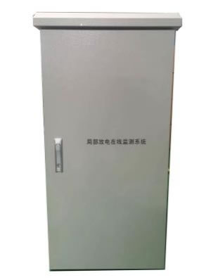
完全な オンラインPDモニタリングシステム consists of three functional layers that work together to convert raw discharge signals into actionable diagnostic intelligence.
Field Sensors
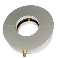
Three types of sensors are deployed on the transformer to capture different physical manifestations of partial discharge. Ultrasonic sensors detect acoustic emissions from PD activity within the windings and oil. High-frequency current (HFCT) sensors clamp onto the core grounding cable to measure pulse currents generated by discharge events. UHF sensors are installed at oil valve ports to capture ultra-high-frequency electromagnetic radiation propagating through the transformer oil. Each sensor is designed for harsh outdoor environments with an IP68 protection rating.
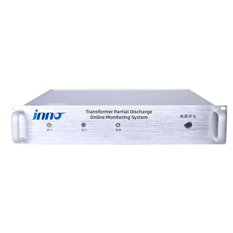
PD監視上位装置
The monitoring host is the central processing hub of the system. It receives analogue signals from all connected sensors, 信号調整を実行します (増幅, フィルタリング, and impedance matching), and digitises the waveforms at high speed using a multi-channel acquisition architecture. ホストは、最大放電振幅を含む主要な PD パラメータを計算します。, 平均排出量, および放電頻度 — パターン認識と故障分類にインテリジェントなアルゴリズムを適用します. 通常、変圧器の近くのコンバージェンスキャビネットまたはコントロールパネル内の 2U エンクロージャにラックマウントされます。.
バックエンド監視ソフトウェア
制御室のコンピュータまたはサーバーにインストール, ソフトウェア プラットフォームはリアルタイムの視覚化を提供します, 歴史的傾向, アラーム管理, および診断分析. その中核となる分析機能には、3D PRPD パターン表示が含まれます。, PRPSパルスシーケンスマッピング, 放電振幅統計, 自動化された PD タイプ識別のためのエキスパート パターン データベースとの比較. ソフトウェアはイーサネットまたは RS-485 経由で監視ホストと通信します。.
6. センサーの設置, Bandwidth, and Function — Ultrasonic, HFCT, and UHF Explained
の有効性 部分放電監視システム 正しいセンサーの選択と配置に大きく依存します. The table below details the three sensor types used in a full-spectrum multi-sensor architecture, including their monitoring bandwidth, installation method, mounting location, and primary diagnostic function.
| センサーの種類 | 帯域幅のモニタリング | 設置方法 | Mounting Location | 一次機能 |
|---|---|---|---|---|
| 超音波センサー | 20 kHz – 200 kHz | Magnetic mount | Transformer tank surface | Detects acoustic emission signals generated by internal PD activity in windings and insulation structures |
| 高周波電流 (HFCT) センサー | 100 kHz – 50 MHz | Clamp-on | Core grounding point | Captures high-frequency pulse currents flowing through the grounding cable as a result of discharge events |
| UHFセンサー | 300 MHz – 3 000 MHz | Plug-in type | Oil drain valve port | Monitors ultra-high-frequency electromagnetic signals propagating through transformer oil, indicating internal insulation discharge |
Installation Notes
Ultrasonic sensors attach to the tank wall using a magnetic holder, which allows flexible repositioning without drilling or welding. For optimal acoustic coupling, a thin layer of couplant gel is applied between the sensor face and the tank surface. The HFCT sensor is a split-core clamp that can be installed around the grounding cable without disconnecting it — meaning no transformer outage is required. The UHF sensor inserts into an existing oil drain valve or dedicated dielectric window port, 内部の電磁信号に対する感度を最大にするために、アンテナ要素をオイルスペース内に配置します。. 3 種類のセンサーはすべて IP68 等級に準拠しています, 雨天でも確実な動作を確保, ほこり, 湿度, と極端な気温から -20 ℃~ +125 ℃.
7. Key Technical Specifications of the PD Monitoring Host Unit
監視ホストはシステムの中心です, 高速信号取得を担当, real-time processing, and data communication. 以下の表は、代表的な工業用グレードの主要な技術パラメータを示しています。 PD監視ホスト 変電所の導入向けに設計.
| パラメータ | 仕様 |
|---|---|
| 信号受信 | 超音波, 高周波電流 (HFCT), およびUHFセンサー入力 |
| ダイナミックレンジ | -80 に -20 dBm |
| サンプリングレート | 200 MS/秒 (200 毎秒百万サンプル) |
| チャネル構成 | 4 または 6 チャンネル (ユーザー設定可能) |
| チャネルの一貫性 | ≤ 0.5 dBm |
| 監視範囲 | ≤ 20 000 パソコン |
| 伝送インピーダンス | ≥ 12 mV/mA |
| 通信インターフェース | RJ45イーサネット, RS-485 |
| Supported Protocols | Modbus RTU/TCP, IEC 61850, DNP3 |
| 電源 | AC90~240V, 50/60 Hz |
| Enclosure | 2Uラックマウント (483 mm× 89 mm× 300 mm) |
| 設置方法 | コンバージェンスキャビネットまたはコントロールパネルマウント |
| センサー保護定格 | IP68 |
| 動作温度 | -20 ℃~ +125 ℃ (センサー); キャビネットごとのホスト環境 |
| Diagnostic Outputs | 放電の大きさ (Q), 放電段階 (Ø), 3D PRPD patterns, PRPSパルスシーケンス, 最大振幅, 平均的な量, 放電頻度 |
なぜ 200 MS/s Sampling Rate Matters
Partial discharge pulses are extremely fast transient events, often lasting only nanoseconds. A sampling rate of 200 MS/s — equivalent to a 5-nanosecond sampling interval — ensures that the host captures the full waveform of each discharge pulse without aliasing or distortion. This waveform fidelity is essential for accurate PRPD pattern construction and for distinguishing genuine PD pulses from noise artefacts. Lower sampling rates may miss critical waveform features, leading to misclassification or missed detections.
8. How Do PRPD 3D Patterns and PRPS Pulse Sequences Identify Discharge Types?
Raw PD data — pulse counts, amplitudes, and timestamps — becomes truly diagnostic when it is visualised through 位相分解部分放電 (PRPD) patterns and 位相分解パルスシーケンス (PRPS) ディスプレイ.
PRPD — The Fingerprint of Discharge
A PRPD pattern plots discharge magnitude (vertical axis) against the phase angle of the power-frequency cycle (horizontal axis), accumulated over many cycles to build a three-dimensional density map. Different PD types produce distinctly different PRPD shapes. Corona discharge typically appears as clusters concentrated near the voltage peaks on one polarity. Internal void discharge produces symmetrical patterns on both positive and negative half-cycles, with the discharge magnitude remaining relatively constant. Surface discharge shows asymmetric, spreading patterns that increase in magnitude with applied voltage. Floating-potential discharge creates dense, high-amplitude clusters that shift in phase as the floating voltage changes.
By comparing a measured PRPD pattern against an expert database of known discharge signatures, the monitoring software can automatically classify the PD type and assess its severity — transforming a complex electromagnetic phenomenon into an actionable maintenance recommendation.
PRPS — Tracking Discharge Evolution Over Time
While PRPD provides a cumulative snapshot, PRPS displays individual pulses in sequence, preserving the time relationship between consecutive discharge events. This is particularly valuable for detecting intermittent PD activity, observing how discharge patterns evolve under changing load or temperature conditions, and distinguishing between multiple simultaneous PD sources. PRPS data also supports advanced statistical analysis — such as pulse interval distributions and clustering algorithms — that can reveal degradation trends before they are visible in the PRPD pattern alone.
9. Backend Monitoring Software — Features and Diagnostic Capabilities
The backend software platform transforms the monitoring host’s raw output into a decision-support tool for operators and asset managers. Installed on a control room workstation or accessible via a web interface, it provides four core functional modules.
Real-Time Monitoring and Visualisation
システムはライブ PD データを継続的に取得して表示します, 3D PRPD スペクトル マップを含む, PRPSパルスシーケンス, 放電振幅棒グラフ, 最大流量などの重要なパラメータの傾向線, 平均排出量, と吐出繰り返し率. オペレーターは、個々のチャネル データまたは集約されたシステム レベルの概要を表示できます。.
履歴クエリとトレンド
すべての測定データはタイムスタンプ付きで保存されます, エンジニアが日付範囲ごとに履歴レコードをクエリできるようにする, チャネル, またはアラームイベント. 統計的傾向ツールにより長期的な絶縁劣化の軌跡が明らかに, 季節変動, および負荷相関 PD 動作. 傾向予測アルゴリズムにより、予知保全のスケジュール設定がサポートされます。.
アラーム管理
マルチレベルのアラームしきい値 - 通常は情報提供, 警告, および重要 — 監視対象パラメータごとに設定可能. しきい値を超えたとき, システムはダッシュボード上に視覚的なアラートを生成し、電子メールで通知を送信します。, SMS, またはリレー出力. アラーム イベントは完全なコンテキストでログに記録されます (タイムスタンプ, チャネル, パラメータ値, PRPD スナップショット) イベント後の分析用.
インテリジェントな診断
このソフトウェアには、PRPD および PRPS シグネチャを既知の放電タイプにマッピングする内蔵のエキスパート パターン データベースが含まれています. 新しいデータが保存されたパターンと一致する場合, システムは最も可能性の高い PD タイプと推奨されるアクションを提案します。. これにより、手動による専門家の解釈への依存が軽減され、意思決定プロセスが加速されます。, 特に大規模な変圧器群を管理する電力会社向け.
10. PD モニタリング システムは SCADA および資産管理プラットフォームとどのように統合されますか?
Partial discharge data delivers maximum value when it is embedded in the utility’s wider operational data ecosystem rather than confined to a standalone display. A well-designed PD monitoring system supports this integration through standard industrial communication interfaces and protocols.
変電所レベルで, the PD monitoring host connects to the station RTU (Remote Terminal Unit) またはベイコントローラー経由 RJ45イーサネット または RS-485. Standard protocols — including Modbus RTU/TCP, IEC 61850, そして DNP3 — ensure compatibility with virtually any substation automation architecture. Key data points transmitted to スカダ include real-time PD amplitude values, alarm status flags, and diagnostic summary codes. Dispatchers can configure high-priority alarms for critical PD events — such as sudden acetylene-type UHF signatures or rapidly increasing discharge rates — ensuring immediate visibility on the SCADA overview screen.
Correlation with Other Monitoring Parameters
The greatest diagnostic insight comes from correlating PD data with complementary transformer health parameters. When the PD monitoring system feeds data into an integrated 変圧器監視プラットフォーム alongside dissolved gas analysis (DGA), fibre optic winding temperature, bushing capacitance and tan-delta, and on-load tap changer condition data, the platform can perform automated cross-parameter analysis. 例えば, a simultaneous increase in UHF PD activity and a rise in hydrogen concentration in the oil provides much stronger confirmation of an active internal insulation fault than either indicator alone. This multi-parameter correlation approach significantly reduces diagnostic uncertainty and supports more confident maintenance decision-making.
11. オンライン部分放電監視から最も恩恵を受ける変圧器はどれですか?
While any oil-filled or dry-type transformer can experience partial discharge, the investment in continuous online monitoring is best directed at assets where the consequences of an undetected insulation fault are most severe.
Highest-Priority Applications
Transmission-voltage power transformers (≥110 kV) at utility substations are the primary candidates, as their failure causes widespread outages and replacement lead times can exceed twelve months. 発電機のステップアップ (GSU) transformers at thermal, ハイドロ, and nuclear power plants are equally critical because an unplanned trip directly removes generation capacity from the grid. Large industrial transformers serving petrochemical complexes, semiconductor fabrication plants, data centres, and steel mills also justify online PD monitoring due to the enormous cost of production downtime.
Growing Adoption Scenarios
The expansion of renewable energy has created new demand. Collector and interconnection transformers at 風力発電所 そして solar farms experience highly variable loading profiles and are often in remote locations where periodic manual testing is expensive and infrequent. Traction power transformers for 鉄道電化 systems carry safety-critical loads. Ageing transformers operating beyond their original design life are another strong candidate — continuous PD trending supports evidence-based lifetime extension decisions. 高電圧 開閉装置, GIS (ガス絶縁開閉装置), そして power cable systems are also increasingly equipped with online PD monitoring, using the same sensor technologies adapted for their specific enclosure geometries.
12. 適切な部分放電監視装置を選択する方法 — バイヤーズガイド
The market offers a range of PD monitoring products, from single-sensor screening devices to full multi-sensor diagnostic platforms. The following criteria will help buyers match the right equipment to their specific application requirements.
Sensor Coverage and Fusion Capability
For comprehensive diagnostics on critical transformers, specify a system that supports all three sensor types — ultrasonic, HFCT, and UHF — with true multi-channel data fusion. Single-sensor systems (例えば, UHF-only or acoustic-only) are suitable for basic screening but cannot provide the cross-verification and source localisation capabilities that multi-sensor fusion delivers.
Sampling Rate and Dynamic Range
A sampling rate of at least 200 MS/s ensures that fast PD transients are captured without loss of waveform detail. The dynamic range should be wide enough — at least -80 に -20 dBm — to handle both very small incipient discharges and large discharge events without saturation or signal clipping.
Channel Count and Scalability
Evaluate whether four channels suffice for the intended transformer or whether six channels are needed to accommodate additional sensor positions. Systems with configurable channel options provide flexibility for both initial deployment and future expansion.
Diagnostic Software Quality
ソフトウェアには 3D PRPD パターン表示が含まれている必要があります, PRPSの可視化, 自動化された PD タイプ分類のためのエキスパート パターン データベース, マルチレベルのアラーム管理, 予測による過去の傾向分析. Web ベースまたはリモート アクセス機能は、フリート全体の管理にますます期待されています.
通信プロトコルの互換性
監視ホストが、変電所ですでに使用されている通信プロトコルをサポートしていることを確認します。 Modbus RTU, Modbus TCP, IEC 61850, または DNP3. ネイティブ プロトコル サポートにより、外部プロトコル コンバーターを追加するコストと複雑さを回避できます。.
環境評価とセンサーの耐久性
センサーは屋外設置の場合は IP68 等級に準拠し、設置場所の全動作温度範囲に対して指定されている必要があります。. センサーの取り付け方法 - 磁気, クランプオン, およびプラグイン - 変圧器の構造に変更を加えたり、設置のために停止したりする必要はありません。.
ベンダーサポートとエキスパートデータベースの更新
PD パターン認識の精度は、専門家データベースの品質と幅広さに依存します。. 設置ベース全体でフィールド経験が蓄積されるにつれて、新しい放電パターンと診断の改善を組み込んだ定期的なデータベース更新を提供するベンダーを選択してください。.
13. 部分放電の試験および監視に適用される国際規格
部分放電測定を規定するいくつかの国際規格, 解釈, そして設備の性能も. これらの参考資料を理解することは、バイヤーがより適切な調達仕様を作成し、選択した監視システムが世界的に受け入れられているベンチマークを確実に満たすようにするのに役立ちます。.
IEC 60270 (高電圧試験技術 - 部分放電測定) 電気的PD測定の基本的な標準です. 見かけの充電方法を定義します, 校正手順, およびテスト回路構成. 主にオフラインの工場テストを目的としていますが、, その測定原理は多くのオンライン システム設計を支えています.
IEC 62478 (高電圧試験技術 - 電磁法および音響法による部分放電の測定) 標準フレームワークを拡張して、UHF および音響検出技術をカバーします, センサー仕様に関するガイダンスの提供, 信号処理, オンラインモニタリングで使用される従来とは異なるPD測定方法のデータプレゼンテーションと.
IEEE C57.127 (検出ガイド, 位置, および電力変圧器およびリアクトルにおける放電からの音響放射源の解釈) 特に変圧器における音響 PD 検出に焦点を当てています, センサーの配置をカバーする, 信号解釈, およびソース位置特定技術.
追加の参考文献には以下が含まれます CIGRE技術パンフレット 676 (Partial Discharges in Transformers) which provides comprehensive guidance on PD phenomena, measurement techniques, and interpretation strategies, そして IEC 61850 which defines the communication standard for substation automation and governs how PD monitoring data is exchanged with SCADA and asset management systems.
14. よくある質問 (よくある質問)
Q1: What is the difference between partial discharge and full breakdown?
Partial discharge is a localised insulation breakdown that bridges only part of the insulation gap between conductors. It does not create a complete conductive path and does not cause immediate equipment failure. Full breakdown, 対照的に, represents a complete insulation failure — a short circuit that typically results in catastrophic damage, an explosion, or fire. Partial discharge is the precursor; if left unmonitored and unaddressed, it progressively degrades insulation until full breakdown occurs.
第2四半期: Can partial discharge be detected while the transformer is energised?
はい. オンライン 部分放電監視システム are specifically designed to operate while the transformer is energised and carrying load. The ultrasonic, HFCT, and UHF sensors are all installed without requiring a transformer outage, and the system continuously acquires data under normal operating conditions. 実際には, monitoring PD under real service voltage and load is more representative of the transformer’s actual insulation condition than offline tests performed at reduced voltage.
Q3: How does multi-sensor fusion reduce false alarms?
Each sensor type is sensitive to a different physical phenomenon. A genuine partial discharge event simultaneously produces an acoustic wave (detected by the ultrasonic sensor), 高周波電流パルス (HFCTセンサーで検出), そして電磁信号 (UHFセンサーで検知). 外部干渉源 — スイッチング過渡現象など, 無線信号, または機械的振動 - 通常は 1 つのセンサー タイプのみに影響します. アラームを発する前に、2 つ以上のセンサーにわたる相関検出を要求することによって, このシステムは、単一発生源のノイズによって引き起こされる誤検知を効果的に排除します。.
Q4: PRPD パターンとは何ですか、診断にどのように使用されますか?
あ PRPD (位相分解部分放電) パターンは、AC 電源サイクルの位相角に対して放電の大きさをプロットした 3 次元視覚化です。, 多くのサイクルにわたって蓄積された. さまざまなタイプの部分放電 - コロナ, 沿面放電, 内部空隙, 浮動電位 - それぞれが特徴的な PRPD 形状を生成します. By matching the measured pattern against a database of known discharge signatures, the monitoring system can identify the type of insulation defect and assess its severity, enabling targeted maintenance rather than generic inspections.
Q5: How long does it take to install a PD monitoring system on an existing transformer?
A typical installation takes one to two days per transformer. Ultrasonic sensors attach magnetically to the tank surface, HFCT sensors clamp onto the core grounding cable, and UHF sensors plug into existing oil drain valve ports — none of these steps require a transformer outage. The monitoring host is rack-mounted inside a nearby control cabinet, connected to the sensors via signal cables, and linked to the control room via Ethernet or RS-485. 試運転, 校正検証, and operator training are typically completed on-site within the same visit.
Q6: What maintenance does the PD monitoring system itself require?
システムには最小限のメンテナンスが必要です. Recommended activities include quarterly visual inspection of sensor mounting integrity and cable connections, annual calibration verification using a reference signal source, and periodic software updates to incorporate the latest diagnostic algorithms and expert pattern database revisions. The sensors themselves are maintenance-free with IP68 environmental protection. Data storage capacity should be monitored to prevent disk space issues on the backend server.
Q7: Can the system monitor multiple transformers simultaneously?
はい. The backend monitoring software supports a multi-asset architecture where multiple PD monitoring hosts — each connected to its own set of sensors on a different transformer — report to a single centralised software platform. This N-to-1 configuration is standard for substations and industrial facilities with several transformers, providing fleet-wide visibility from a single operator interface and reducing total system cost.
Q8: How does online PD monitoring complement dissolved gas analysis (DGA)?
DGA detects the chemical by-products of insulation degradation — dissolved gases such as hydrogen and acetylene — that accumulate in transformer oil over time. It is excellent for confirming that insulation damage has occurred, but it responds slowly and cannot pinpoint the location or real-time activity of the discharge source. オンラインPDモニタリング, 対照的に, detects individual discharge events as they happen, identifies the PD type through PRPD analysis, and can localise the source via acoustic triangulation. 一緒に, DGA and PD monitoring provide complementary layers of insulation surveillance — DGA for cumulative damage assessment and PD for real-time fault activity tracking.
Q9: What is the expected return on investment for a PD monitoring system?
ROI is typically realised within two to three years through prevention of catastrophic insulation failures — each of which can cost millions of dollars in equipment replacement, 失われた生産, and collateral damage. A single prevented failure often justifies the entire monitoring system investment. 追加の利点としては、最適化されたメンテナンス スケジュールが挙げられます。 (不必要な停止や検査を回避する), 変圧器の耐用年数を延長, 保険料の軽減, 重要なインフラストラクチャ資産に対する規制遵守の向上.
Q10: SCADA統合でサポートされる通信プロトコルは何ですか?
PD監視ホストが提供するのは、 RJ45イーサネット そして RS-485 通信インターフェース, 以下を含む標準産業プロトコルのサポート Modbus RTU, Modbus TCP, IEC 61850, そして DNP3. これにより、事実上あらゆる変電所自動化または SCADA アーキテクチャとのシームレスな統合が保証されます。. リアルタイムPDデータ, アラームステータス, 診断結果は集中監視センターや企業資産管理に送信できます。 (EAM) プラットフォーム.
免責事項: この記事で提供される情報は、一般的な教育および参考のみを目的としています。. フジノ (www.fjinno.net) いかなる保証も行いません, 明示的または暗黙的, 完成度に関しては, 正確さ, またはコンテンツの特定のプロジェクトまたはインスタレーションへの適用可能性. ここで参照される技術仕様は代表的な値を表しており、変圧器のタイプによって異なる場合があります。, センサーの配置, and site environment. エンジニアリングに関する決定は、常に、IEC を含む該当する規格に従って、資格のある専門家によって実施される現場固有の評価に基づいて行われるべきです。 60270, IEC 62478, IEEE C57.127, およびローカルグリッドコード. サードパーティメーカーの製品名はそれぞれの所有者の商標であり、情報提供のみを目的として記載されています。. FJINNOは、この情報の使用または信頼から生じるいかなる損失または損害についても責任を負いません。.

光ファイバー温度センサー, インテリジェント監視システム, 中国の分散型光ファイバーメーカー
 |
 |
 |