 Sensor suhu serat optik INNO ,sistem pemantauan suhu.
- Trafo terendam minyak adalah salah satu aset bernilai tertinggi di jaringan listrik mana pun — suhu titik panas belitan adalah satu-satunya parameter paling penting yang mengatur masa pakai isolasi.
- Indikator OTI/WTI tradisional mengukur suhu minyak, bukan suhu belitan sebenarnya; kesenjangannya bisa mencapai 20–40 °C saat diberi beban.
- Sensor suhu serat optik neon memberikan langsung, EMI-immune, 100 pengukuran belitan terisolasi kV yang tidak dapat ditandingi oleh sensor konvensional.
- Panduan ini memandu teknisi pengadaan melalui pemilihan teknologi, spesifikasi utama, probe types, sertifikasi, evaluasi pemasok, dan kesalahan pembelian umum.
- Semua tautan produk, studi kasus dunia nyata, dan rincian sertifikasi diambil dari dokumentasi terverifikasi FJINNO.
1. Why Oil-Immersed Transformers Need Pemantauan Suhu Serat Optik
1.1 The Limitation of Conventional OTI and WTI Indicators
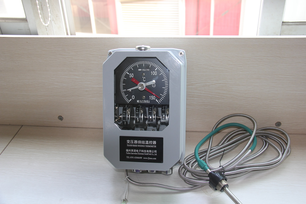
Every oil-immersed power transformer ships with an indikator suhu minyak (SELESAI) Dan, in many cases, A indikator suhu belitan (WTI). Both instruments have served the industry for decades, yet neither delivers what modern asset management requires: a direct, real-time reading of the winding hot-spot temperature.
The OTI measures bulk oil temperature at the top of the tank — a value that lags behind actual winding temperatures by anywhere from a few minutes to over half an hour during load changes. The WTI improves on this by adding a thermal image of the current-dependent heat rise, namun hasilnya masih perkiraan yang dihitung, bukan nilai terukur. Di bawah profil pemuatan non-standar, harmonic distortion, atau kegagalan sebagian sistem pendingin, perkiraan WTI dapat menyimpang dari suhu belitan sebenarnya sebesar 20 °C sampai 40 °C.
Penyimpangan tersebut sangat berarti. Isolasi transformator mengikuti hubungan Arrhenius: setiap peningkatan suhu titik panas yang berkelanjutan sebesar 6–8 °C akan mengurangi masa pakai insulasi menjadi setengahnya (IEC 60076-2). Mengoperasikan trafo 20 °C yang lebih panas dari perkiraan WTI tidak hanya mengurangi harapan hidup — namun juga dapat memicu kerusakan isolasi yang cepat dalam hitungan bulan, bukan dekade.
1.2 Mengapa Sensor PT100 dan Termokopel Tidak Memadai
Detektor suhu resistansi PT100 dan termokopel cukup akurat dalam isolasi, tetapi konstruksi logamnya menimbulkan masalah mendasar dalam lingkungan transformator:
- Electrical safety: Konduktor logam yang disalurkan dari dalam belitan tegangan tinggi ke instrumen yang dipasang di panel menimbulkan risiko dielektrik. Bahkan dengan isolasi yang hati-hati, konduktor mengganggu medan listrik pada belitan dan menciptakan jalur potensial untuk pelepasan sebagian.
- Interferensi elektromagnetik: Medan magnet bolak-balik yang kuat di dalam transformator berenergi menginduksi tegangan pada kabel sinyal logam, merusak pembacaan suhu — terutama pada beban berat atau kondisi gangguan.
- Oil compatibility: Konstruksi RTD standar tidak dirancang untuk perendaman tanpa batas waktu dalam minyak transformator; kegagalan penyegelan menyebabkan kontaminasi oli dan sensor melayang seiring waktu.
1.3 Kasus untuk Pemantauan Suhu Gulungan Serat Optik
Sistem pemantauan suhu serat optik untuk transformator terendam minyak mengatasi setiap batasan yang tercantum di atas dalam satu langkah teknologi:
| Parameter | SELESAI / WTI | PT100RTD | Serat Optik Fluoresen |
|---|---|---|---|
| Jenis pengukuran | Tidak langsung / calculated | Direct contact | Direct contact |
| kekebalan EMI | ✅ | ❌ | ✅ |
| High-voltage isolation | ✅ | ❌ | ✅ (≥100 kV) |
| Akurasi tipikal | ±5 °C (diperkirakan) | ±1 °C | ±1 °C |
| Real-time continuous output | ✅ | ✅ | ✅ |
| Oil submersion compatible | T/A | Terbatas | ✅ (oil-resistant probes) |
| SCADA / Modbus integration | Terbatas | Via transmitter | Native RS485 / Modbus RTU |
2. Tiga Teknologi Suhu Serat Optik Dibandingkan
Istilahnya “sensor suhu serat optik” covers several distinct measurement principles. Choosing the wrong technology for a transformer application is one of the most common — and costly — procurement errors. Here is a plain-language comparison of the three technologies a procurement engineer is most likely to encounter.
2.1 Sensor Serat Optik Fluoresen (Recommended for Transformer Windings)

A sensor suhu serat optik neon — sometimes called a fluorescence lifetime sensor — places a rare-earth phosphor crystal at the tip of a quartz fiber. The controller fires a short light pulse down the fiber; the crystal absorbs the pulse and re-emits a fluorescence signal whose decay time is a precise, repeatable function of temperature. Pengontrol mengukur waktu peluruhan dan mengubahnya menjadi nilai suhu.
Mengapa ini penting bagi transformator: Pengukurannya tergantung pada rasio waktu, bukan pada intensitas ringan. Itu berarti redaman sinyal dari serat yang panjang, connector aging, atau sedikit kontaminasi pada permukaan serat tidak mempengaruhi akurasi. Sensor ini benar-benar merujuk pada diri sendiri.
- Rentang pengukuran: −40 °C hingga +260 °C (standar); dapat disesuaikan untuk +300 °C
- Ketepatan: ±1 °C
- Resolusi: 0.1 °C
- Waktu respons: <1 Kedua
- Probe type: Pengukuran titik — satu probe, satu lokasi
- Best for: Pengukuran titik panas langsung pada belitan transformator, busbar switchgear, sambungan kabel
2.2 Kisi Serat Bragg (FBG) Sensor
Sensor FBG mengkodekan informasi suhu dalam panjang gelombang yang dipantulkan dari pola indeks bias periodik yang ditulis ke dalam inti serat. Beberapa kisi pada panjang gelombang berbeda dapat digandakan menjadi satu serat, sehingga memungkinkan untuk mengambil beberapa pembacaan suhu sepanjang satu untai serat.
- Keuntungan: Pengukuran multi-titik pada satu serat; cocok untuk cakupan belitan terdistribusi pada transformator daya yang sangat besar
- Limitation: Kisi-kisi juga merespons tekanan mekanis, jadi pembengkokan atau getaran dapat menghasilkan pembacaan yang salah kecuali jika kompensasi regangan diterapkan. Interogator (demodulator) secara signifikan lebih kompleks dan mahal dibandingkan pengontrol neon.
- Best for: Aplikasi saluran tinggi di mana biaya per titik harus dikurangi dan lingkungan pemasangan stabil secara mekanis
2.3 Penginderaan Suhu Terdistribusi (DTS)
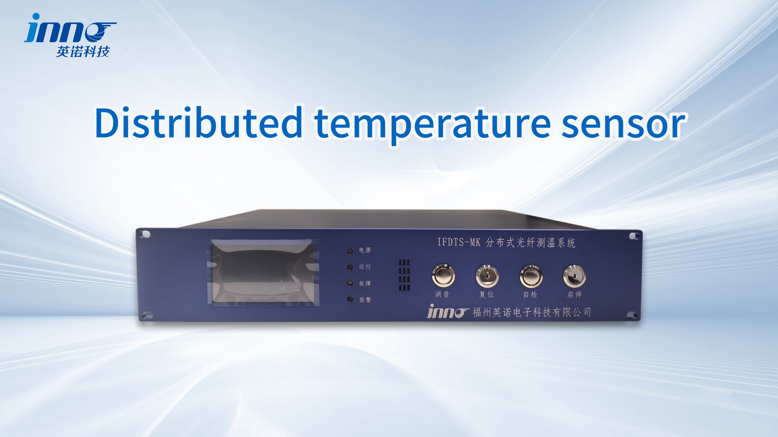
Penginderaan suhu terdistribusi menggunakan hamburan balik Raman atau Brillouin di sepanjang serat mode tunggal atau multimode biasa untuk menghasilkan profil suhu berkelanjutan — ribuan titik pengukuran sepanjang satu kabel hingga panjang beberapa kilometer.
- Keuntungan: Cakupan linier berkelanjutan — ideal untuk terowongan kabel, overhead line monitoring, deteksi kebocoran pipa
- Limitation: Resolusi spasial biasanya 0,5–2 m. Titik panas belitan transformator menempati beberapa sentimeter; DTS cannot resolve it. The system also requires a large interrogator unit and long averaging times to achieve acceptable accuracy.
- Best for: Power cable routes, pipeline temperature profiling — not suitable for transformer winding hot-spot detection
Technology Selection Summary
| Teknologi | Measurement Mode | Transformer Winding Use | Akurasi Khas | Relative System Cost |
|---|---|---|---|---|
| Serat Optik Fluoresen | Titik | ✅ Recommended | ±1 °C | Sedang |
| FBG | Terdistribusi semu | ✅ Suitable (large transformers) | ±1–2 °C | Lebih tinggi |
| DTS | Didistribusikan (linier) | ❌ Not suitable | ±1–2 °C over 1 M | Tinggi |
3. Spesifikasi Teknis Utama Dijelaskan
Supplier datasheets for sistem pengukuran suhu serat optik can look similar on the surface. The following breakdown of each parameter helps procurement engineers read those datasheets critically and ask the right clarifying questions before committing to a purchase.
3.1 Akurasi Pengukuran (±1 °C)
Accuracy specifies the maximum deviation between the sensor’s displayed value and the true temperature under defined conditions. IEC 60076-2 requires that hot-spot temperature measurement uncertainty not exceed ±2 °C for compliance purposes, so a sensor rated at ±1 °C meets this requirement with margin.
What to watch for: Accuracy figures are only meaningful when accompanied by a traceable calibration certificate. Some suppliers quote ±0.5 °C or better without providing supporting calibration data. Always request a calibration certificate for at least one unit per order batch.
3.2 Rentang Pengukuran (−40 °C hingga +260 standar °C)
Transformer winding temperatures under normal service rarely exceed 130 °C (Class A insulation limit per IEC 60076-2 adalah 98 °C hot-spot rise above 40 °C ambient = 138 °C total). Namun, emergency overload conditions, kegagalan sistem pendingin, or insulation degradation can push winding temperatures above 180 °C. The standard range of −40 °C to +260 °C covers all realistic scenarios with comfortable margin.
Probe tip temperature vs. controller ambient: Confirm that the probe tip rating covers the maximum winding temperature, and separately confirm that the controller enclosure rating covers the ambient temperature at its installation location (often 0–55 °C for standard industrial units).
3.3 Number of Measurement Channels
Each channel supports one pemeriksaan suhu serat optik. Selecting the correct channel count is a balance between monitoring completeness and system cost.
- Small distribution transformer (hingga 2 MVA): 3 channels — one per phase winding top
- Medium power transformer (2–50 MVA): 6–9 channels — top and bottom of each phase winding
- Large power transformer (50 MVA+): 9–16 channels — multiple points per winding plus tap changer and bushing positions
FJINNO controllers support 1 ke 64 saluran, with custom configurations available for large installations.
3.4 Waktu Respons (<1 Kedua)
Response time defines how quickly the sensor tracks a step change in temperature. Sub-second response captures transient overload events — for example, a through-fault that superheats windings in milliseconds — giving protection relays meaningful data rather than lagged readings.
3.5 High-Voltage Dielectric Isolation (100 persegi panjang)
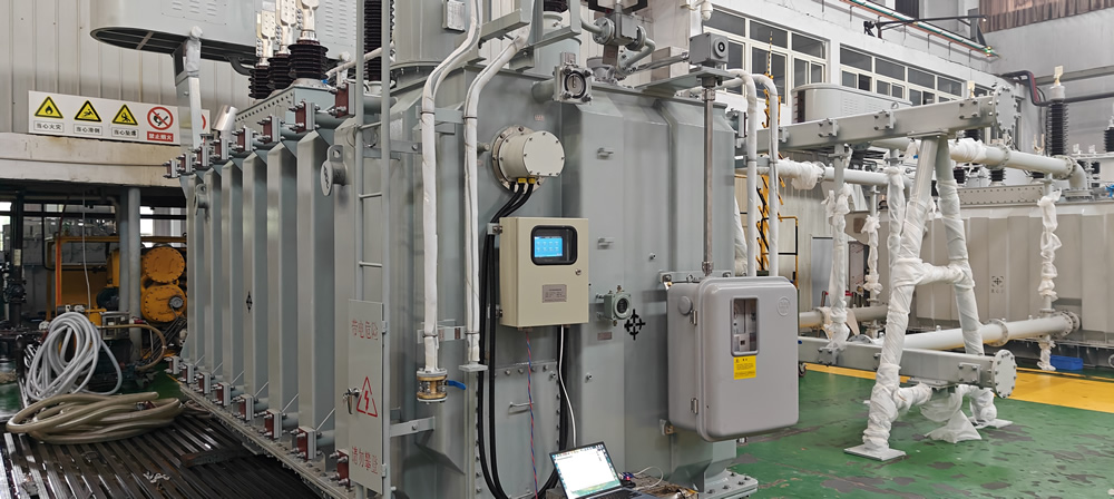
This is the specification that separates fiber optic sensors from all metallic alternatives. The quartz fiber itself has no electrical conductivity; combined with the all-dielectric probe housing, the sensor presents no leakage path between the live winding and the measurement circuit. FJINNO probes are rated at 100 kV continuous dielectric isolation, penutup 10 persegi panjang, 35 persegi panjang, 110 persegi panjang, Dan 220 kV transformer classes.
3.6 Antarmuka Komunikasi
Standard output is RS485 / Modbus RTU, compatible with virtually all substation SCADA platforms. For installations integrated into IEC 61850 gardu digital, confirm whether the controller supports IEC 61850 natively or requires an external gateway. A 4–20 mA analogue output is useful for interfacing with older DCS systems.
3.7 IP Protection Rating
Controllers mounted on transformer tanks require a minimum of IP54 (dust-protected, splash-resistant). IP65 is preferred for outdoor installations or positions subject to wash-down. Probes immersed in transformer oil require oil compatibility testing per IEC 60296, not just an IP rating.
3.8 Probe Fiber Length
Itu extension cable for fluorescent fiber optic temperature sensors bridges the distance between the probe tip inside the winding and the controller mounted on the tank wall or in a nearby panel. Standard lengths run 3–5 m; FJINNO supports custom fiber lengths from 0 ke 80 m for large transformers or remote control room installations.
Specification Quick-Reference Table
| Parameter | Minimum Acceptable | Direkomendasikan | FJINNO Standard |
|---|---|---|---|
| Ketepatan | ±2 °C | ±1 °C | ±1 °C |
| Kisaran suhu | −20 °C hingga +180 °C | −40 °C hingga +200 °C | −40 °C hingga +260 °C |
| Waktu respons | ≤5 s | ≤1 s | <1 S |
| Dielectric isolation | ≥10 kV | ≥100 kV | 100 persegi panjang |
| Komunikasi | RS485 | RS485 + optional IEC 61850 | RS485 / Modbus RTU |
| Controller IP rating | IP54 | IP65 | IP65 (available) |
| Saluran | 3 | 6–9 (per transformator) | 1–64 (dapat disesuaikan) |
4. Probe Types and Installation Positions

4.1 Armored Probe for Oil-Immersed Winding Applications
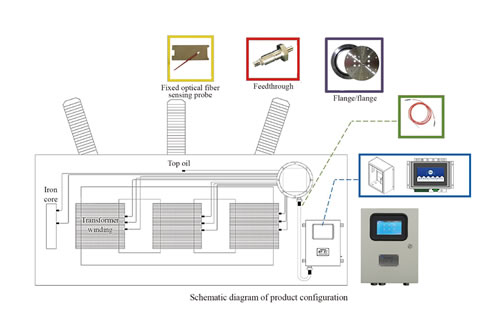
Itu armored fluorescent fiber optic temperature sensor for oil-immersed transformer windings features a stainless-steel protective sheath over the sensing tip and fiber cable. The armor protects the delicate quartz fiber during the winding-insertion process and provides long-term mechanical durability inside the oil tank.
When to specify: Any oil-immersed transformer where the probe must be threaded between winding layers during manufacture or field installation. The armor prevents kinking and protects against abrasion from conductor edges.
4.2 Standard Fluorescent Fiber Optic Probe
Itu fiber optic temperature sensor for oil-immersed transformer winding temperature measurement in its standard form uses a PEEK or stainless-steel tip housing with the quartz fiber encased in a flexible protective jacket. This configuration suits installations where the fiber routing is smooth and the probe is installed during transformer manufacturing with careful handling procedures.
4.3 Fluorescent Fiber Optic Sensor Probes (Multi-Point Kits)
Fluorescent fiber optic temperature sensor probes are available as matched sets configured for specific transformer layouts — for example, a nine-probe kit for a three-phase, three-winding transformer with three measurement points per phase. Pre-matched sets simplify procurement and ensure all probes in the system are calibrated against the same reference.
4.4 Recommended Installation Positions per IEC 60076-2
IEC 60076-2 identifies the winding hot spot as the location most critical for insulation life management. Engineering best practice places probes at the following positions:
- High-voltage winding (HV): Top of winding (highest temperature zone under normal load) — 1 probe minimum; atas + bottom preferred
- Low-voltage winding (LV): Top of winding — 1 probe minimum
- Tertiary or stabilizing winding (if present): Top of winding — 1 menguji
- Inti (large units): Core surface near flux concentration zones — 1 probe optional, recommended for 100 MVA+
- Top oil reference: 1 probe in oil to correlate fiber optic readings with traditional OTI
4.5 New-Build vs. Instalasi Retrofit
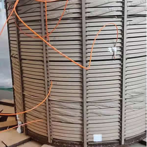
The most accurate installation occurs during transformer manufacturing, when probes are threaded between conductor layers before winding is complete. For retrofit on an existing transformer, probes are inserted through oil-fill valves, drain ports, or purpose-installed oil-tight cable glands. Retrofit accuracy is slightly lower because probe-to-conductor contact cannot be as precisely controlled, but the measurement still substantially outperforms OTI/WTI estimation.
5. Certifications and Compliance Requirements
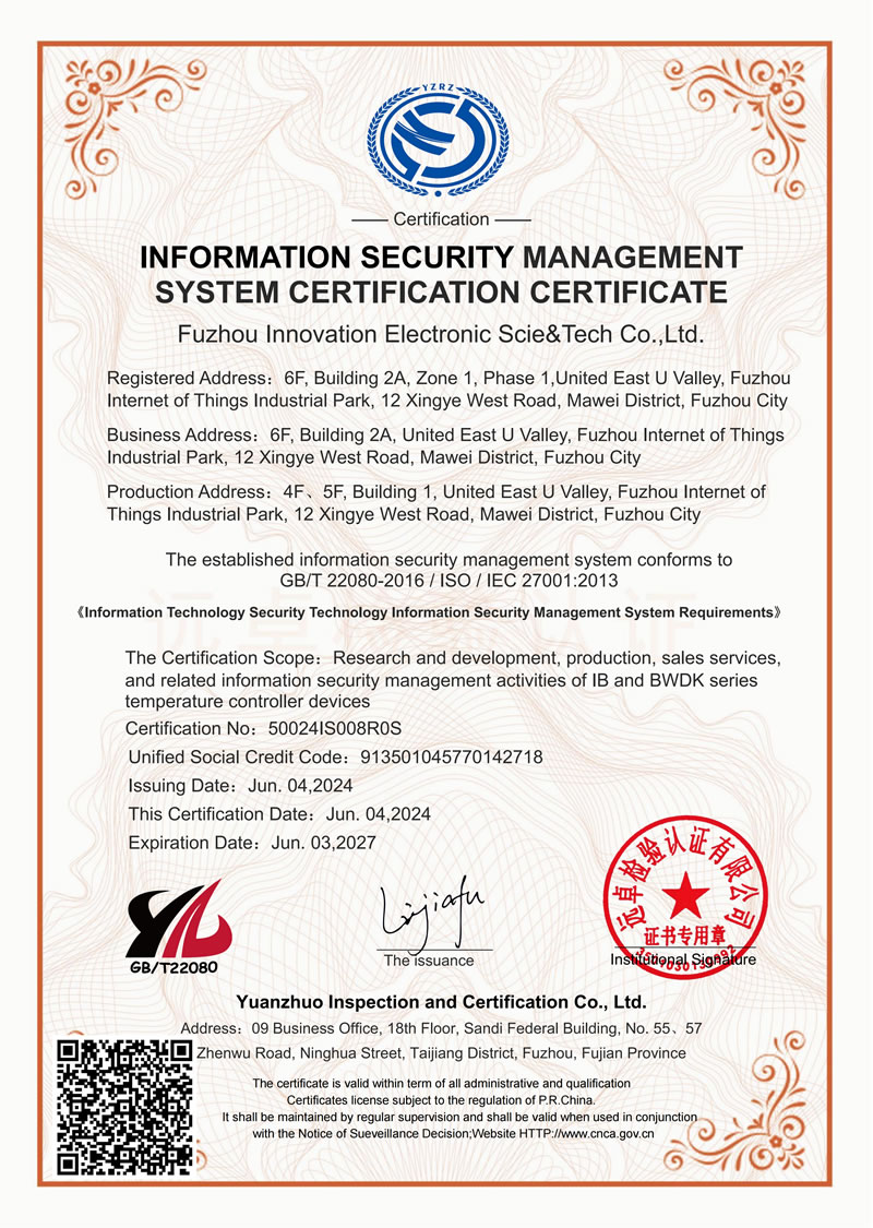
5.1 Mandatory Product Certifications
For projects in most international markets, the following certifications are non-negotiable:
- CE Marking: Required for equipment sold in the European Economic Area. Covers electromagnetic compatibility (EMC Directive 2014/30/EU) and low-voltage safety (LVD 2014/35/EU). Always request the Declaration of Conformity document, not just the CE logo on the label.
- RoHS Compliance: Pembatasan Bahan Berbahaya (EU Directive 2011/65/EU). Most utility and industrial projects globally specify RoHS compliance even outside the EU.
- ISO 9001 Quality Management: Demonstrates that the manufacturer operates under a documented, audited quality system. Request the current certificate with its scope of certification and expiry date.
FJINNO’s full certification portfolio is available at https://www.fjinno.net/certificates.
5.2 Relevant Industry Standards
- IEC 60076-2: Power transformers — Temperature rise for liquid-immersed transformers. Defines hot-spot temperature limits and measurement requirements that fiber optic systems must satisfy.
- IEC 60076-7: Loading guide for oil-immersed power transformers. Specifies how hot-spot measurements feed into thermal models for overload management.
- IEC 61850: Communication networks and systems for power utility automation. Relevant if the temperature monitoring system must integrate into a digital substation architecture.
- IEC 60296: Fluids for electrotechnical applications — unused mineral insulating oils. Probe materials must be compatible with transformer oil as defined in this standard.
5.3 How to Write Certification Requirements Into a Procurement Specification
The following language can be copied directly into a technical specification or tender document:
“The fiber optic winding temperature monitoring system shall carry CE marking with supporting Declaration of Conformity, RoHS compliance documentation, and be manufactured under an ISO 9001-certified quality management system. Products shall comply with IEC 60076-2 for measurement accuracy requirements. Communication interfaces shall support Modbus RTU as a minimum; IEC 61850 GOOSE and sampled values integration shall be provided where specified on individual transformer data sheets.”
6. Supplier Evaluation Checklist
Pasar untuk fiber optic transformer temperature monitoring systems ranges from established specialist manufacturers to resellers offering white-label products with unknown provenance. The following checklist helps procurement engineers separate credible suppliers from those carrying commercial risk.
6.1 Kemampuan Teknis
- Does the supplier manufacture the fluorescent probe tip in-house, or source it from a third party?
- Can they provide a traceable calibration certificate for each sensor?
- Do they have documented oil-immersion soak test data (minimum 1,000 hours in transformer oil per IEC 60296)?
- Can they supply probe installation drawings dimensioned to fit your specific transformer manufacturer’s winding geometry?
- Do they support custom channel counts, fiber lengths, dan protokol komunikasi?
6.2 Delivery and Logistics
- Standard lead time for a 10-unit order (benchmark: 4–8 weeks for custom configurations)
- Availability of safety stock for common configurations to cover urgent replacement needs
- Experience with export documentation for your import jurisdiction
- OEM and ODM capability if you require branded or integrated products
6.3 After-Sales Support
- Warranty period — request a minimum of 24 months on both probe and controller
- Can individual probes be replaced without replacing the complete controller?
- Is English-language technical documentation available (installation manual, Modbus register map, diagram pengkabelan)?
- Is remote commissioning support available via video call or TeamViewer?
- What is the escalation path for a warranty claim?
6.4 Ten Questions to Ask Every Shortlisted Supplier
- What is the continuous dielectric isolation voltage of the probe from tip to connector?
- Can you provide an individual calibration certificate for every probe in my order?
- What probe housing material is used, and how was oil compatibility confirmed?
- What is the maximum fiber optic cable length you can supply without signal repeaters?
- What communication protocols does the controller support natively?
- What are your separate warranty terms for the probe versus the controller?
- Can you supply reference contacts at a transformer OEM or utility that has deployed your system at 110 kV or above?
- Can you provide the probe mechanical drawing for review by our transformer manufacturer?
- What is your standard lead time for a 20-unit order, and do you hold buffer stock?
- Do you support third-party factory acceptance testing at your facility?
7. Common Procurement Mistakes to Avoid
The following errors appear repeatedly in project post-mortems. Each is preventable at the specification stage.
❌ Mistake 1 — Specifying DTS for winding hot-spot measurement
Distributed temperature sensing systems are appropriate for cable routes and pipelines, not for transformer winding hot spots. The 0.5–2 m spatial resolution of DTS cannot locate a hot spot that occupies a few conductor turns. Specify point-type sensor serat optik neon for winding applications.
❌ Mistake 2 — Selecting channel count based on budget rather than measurement strategy
Under-instrumenting a transformer — installing only one probe on a three-phase winding, for example — saves money on day one and creates a significant blind spot. If the hot phase is not monitored, the system gives false comfort. Follow the IEC 60076-2 minimum positions described in Section 4.4.
❌ Mistake 3 — Ignoring communication protocol compatibility
A sensor that arrives on site with only a proprietary ASCII protocol cannot be integrated into a Modbus-based SCADA without a custom gateway. Confirm the exact protocol, register map, and baud rate settings before purchasing. Request a Modbus register map as part of the quotation package.
❌ Mistake 4 — Accepting accuracy claims without calibration evidence
An uncertified ±0.5 °C claim is worth less than a certified ±1 °C claim. For critical protection applications, require per-unit calibration certificates traceable to a national metrology standard.
❌ Mistake 5 — Purchasing from a reseller with no direct access to the manufacturer
If the selling entity cannot answer technical questions about probe construction, oil soak test data, or installation procedure, they are unlikely to support you effectively when a problem arises in service. Verify that your point of contact has direct access to engineering staff at the actual manufacturing facility.
❌ Mistake 6 — Overlooking probe oil compatibility
A probe rated to 260 °C thermally may still fail prematurely if its housing material absorbs transformer oil, swells, and delaminates the sensing crystal. Ask specifically whether the probe has been tested in transformer mineral oil per IEC 60296, and for how long.
8. Studi Kasus Dunia Nyata

8.1 Fluorescent Fiber Optic Temperature Measurement in Oil-Immersed Transformer Windings
FJINNO’s documented case study on fluorescent fiber optic temperature measurement of oil-immersed transformer windings demonstrates how point-type sensors installed during manufacturing provide continuous hot-spot data that feeds directly into the transformer’s thermal protection relay. The installation covers high-voltage, low-voltage, and neutral-point positions, with fiber lengths routed through oil-tight cable glands to an external multi-channel controller.
Key outcomes documented in the case study include detection of a localized cooling obstruction that raised one phase winding 18 °C di atas pembacaan OTI — perbedaan yang tidak akan terlihat tanpa pengukuran belitan langsung.
8.2 110 kV Pemantauan Online Transformator Berinsulasi Hibrid di Gardu Induk
Itu 110 pemantauan online trafo oli berinsulasi hibrida kV kasus pemasangan menjelaskan integrasi sistem suhu belitan serat optik 12 saluran dengan IEC gardu induk 61850 communication architecture. Output Modbus pengontrol memberi makan gateway protokol, yang menyajikan data suhu sebagai IEC 61850 node logis ke sistem otomasi gardu induk.
Instalasi ini menggambarkan pentingnya memastikan kompatibilitas protokol komunikasi sebelum pengadaan — proyek memerlukan satu konverter protokol tambahan yang tidak diperlukan jika IEC 61850 dukungan asli telah ditentukan sejak awal.
9. How FJINNO’s Products Fit This Application

FJINNO — Fuzhou Innovation Electronic Science & Technology Co., Ltd. — telah diproduksi sensor suhu serat optik neon dan lengkap sistem pemantauan suhu transformator untuk utilitas listrik, OEM transformator, and EPC contractors across more than 20 negara. The product range specifically designed for oil-immersed transformer applications includes:
- Pemeriksaan Suhu Serat Optik — Standard point-type fluorescent probe, 1–64 channels, −40 °C hingga +260 °C, ±1 °C, 100 kV isolation, RS485/Modbus RTU, customizable fiber length 0–80 m
- Sensor Suhu Serat Optik Fluoresen Lapis Baja untuk Gulungan Transformator Terendam Minyak — Mechanically protected probe for installation into energized or factory-wound transformer coils
- Fiber Optic Temperature Sensor for Oil-Immersed Transformer Winding Temperature Measurement — Application-specific configuration with oil-compatible housing materials and matching controller
- Probe Sensor Suhu Serat Optik Fluoresen — Multi-probe kits matched to specific transformer winding layouts
- Kabel Ekstensi untuk Sensor Suhu Serat Optik Fluoresen — Custom-length fiber extension for routing from winding to external controller
- Fiber Optic Temperature Measurement System for Oil-Immersed Transformers — Complete integrated system including controller, probe, kabel, pemasangan perangkat keras, and software
The complete transformer temperature monitoring solution covers system design, probe placement guidance, controller configuration, and SCADA integration support. Procurement teams can view the full transformer monitoring solutions portfolio for an overview of all available configurations.
FJINNO holds CE, RoHS, dan ISO 9001 certifications — all verifiable at https://www.fjinno.net/certificates. Itu services page details OEM, ODM, custom design, and technical support offerings.
To request a project-specific configuration and quotation, use the Dapatkan Penawaran form or contact the technical sales team directly.
10. Pertanyaan yang Sering Diajukan
Q1: What is the difference between an OTI and a winding temperature indicator, and why are both inadequate for hot-spot monitoring?
An OTI (indikator suhu minyak) measures the temperature of bulk oil at the transformer tank top — a value that lags actual winding temperature by up to 40 °C under transient load. A WTI (indikator suhu belitan) improves on this by adding a simulated thermal image driven by load current, but the result is still a calculation, bukan pengukuran. Both instruments assume uniform thermal behavior that deviates significantly under non-standard loading, cooling system faults, or harmonic distortion. Langsung fiber optic winding temperature sensors measure actual conductor temperatures at defined positions, eliminating estimation error entirely.
Q2: Can a fluorescent fiber optic sensor be installed in an existing transformer without draining the oil?
Retrofit installation without full oil drain is possible in transformers equipped with suitable access ports — oil-fill valves, drain ports, or purpose-installed oil-tight cable glands. The probe is inserted through the port using a flexible guide tube and positioned at the target winding location. Measurement accuracy with retrofit probes is slightly lower than factory-installed probes because exact probe-to-conductor contact cannot be guaranteed, but the reading still substantially outperforms OTI/WTI estimation. Contact FJINNO’s technical team for guidance specific to your transformer type.
Q3: How many measurement channels does a typical 40 MVA power transformer require?
A 40 MVA three-phase two-winding transformer typically warrants 6 channels as a minimum: one probe at the top of each HV phase winding and one at the top of each LV phase winding. Adding probes at the winding bottoms increases the count to 12 but provides a complete thermal profile that supports dynamic loading calculations per IEC 60076-7. The optimal channel count depends on transformer voltage class, kekritisan, and whether the system feeds a thermal model or a simple alarm function.
Q4: What does “100 kV dielectric isolation” mean in practical terms?
It means the quartz fiber and probe housing present no conductive path between the measurement point (inside a live transformer winding) and the signal-processing electronics in the controller. Itu 100 kV figure is the withstand voltage tested on the complete probe-to-controller assembly. Dalam praktiknya, this allows the probe to be placed in direct contact with live conductors in transformers rated up to 220 kV without any risk of leakage current, ground fault, or electric field distortion at the probe location.
Q5: Is fluorescent fiber optic sensing affected by transformer oil aging or contamination?
The fluorescent crystal at the probe tip is hermetically sealed inside its housing and does not contact the oil directly. The quartz fiber transmission characteristics are also unaffected by external media. Long-term oil aging or contamination therefore does not degrade sensor accuracy. The probe housing material must be compatible with transformer oil per IEC 60296 — FJINNO specifies oil-compatible materials for all transformer probe variants and conducts immersion testing to verify long-term compatibility.
Q6: Can the fiber optic temperature monitoring system integrate with an IEC 61850 substation automation system?
FJINNO controllers provide native RS485/Modbus RTU output. Integration into IEC 61850 architectures is achieved via a Modbus-to-IEC 61850 protocol gateway, which presents temperature data as logical nodes within the substation’s communication infrastructure. Where IEC 61850 native support is required without an external gateway, discuss this requirement explicitly with FJINNO’s technical team at the specification stage.
Q7: How long do fiber optic probes last inside transformer oil?
Fluorescent fiber optic probes designed for oil-immersed applications are rated for service lives aligned with transformer overhaul intervals — typically 20–25 years. The optical measurement principle has no wear mechanism, and the quartz fiber does not degrade in transformer oil. The main life-limiting factor is mechanical integrity of the probe housing and fiber routing under thermal cycling. Correct installation practice — avoiding sharp bends in the fiber and protecting the cable exit from abrasion — is the primary determinant of service life.
Q8: What information should be included in a Request for Quotation (RFQ) for a fiber optic transformer temperature monitoring system?
A well-structured RFQ should include: transformer rating (MVA, kelas tegangan, number of windings), number of probes required and their target installation positions, required fiber length from winding to controller, controller mounting location and available power supply, communication protocol required (Modbus RTU, 4–20 mA, IEC 61850), accuracy and range requirements, environmental conditions at the controller location (suhu, kelembaban, IP class), relevant certifications (CE, RoHS, dll.), and order quantity. The more detail provided, the more accurate and comparable the quotations received will be.
Q9: Is there a risk of the probe affecting transformer winding insulation?
TIDAK, when correctly specified and installed. The probe tip is a small-diameter, all-dielectric element. It introduces no metallic conductor into the winding insulation structure and no electric field distortion. The probe housing materials are selected for compatibility with the winding insulation system (paper/oil for oil-immersed transformers, epoxy-resin for dry-type). FJINNO coordinates with transformer OEMs to confirm probe geometry and material compatibility before supply.
Q10: What after-sales support does FJINNO provide for transformer fiber optic monitoring systems?
FJINNO after-sales services termasuk: detailed installation and commissioning documentation, Modbus register maps and wiring diagrams, remote commissioning support via video call, troubleshooting diagnostics, warranty replacement for faulty components, and technical consultation throughout the product lifecycle. For large installations, on-site commissioning support can be arranged. Contact the technical support team for project-specific arrangements.
Penafian
The information contained in this article is provided for general guidance purposes only and reflects the state of knowledge and product specifications available at the time of writing. Spesifikasi teknis, product configurations, sertifikasi, and service terms are subject to change without notice as part of ongoing product development. Actual product performance in any specific application depends on correct product selection, proper installation, appropriate system configuration, and operating conditions consistent with the product’s rated environment.
Nothing in this article constitutes professional engineering advice, a binding product warranty, or a contractual commitment. All specifications must be confirmed through formal quotation and purchase order documentation before reliance in design or procurement decisions. Compliance with applicable local codes, standar, dan persyaratan peraturan tetap menjadi tanggung jawab pembeli dan pemasang.
FJINNO (Fuzhou Innovation Electronic Science & Technology Co., Ltd.) berhak mengubah spesifikasi produk dan menghentikan model kapan saja. Untuk spesifikasi dan ketersediaan saat ini, kontak https://www.fjinno.net/contact atau kirimkan pertanyaan melalui https://www.fjinno.net/get-a-quote/.
Standar pihak ketiga yang dirujuk dalam artikel ini (IEC 60076-2, IEC 60076-7, IEC 61850, IEC 60296, dll.) adalah milik masing-masing badan penerbitnya. Pembaca harus berkonsultasi langsung dengan versi terbaru dari standar tersebut untuk mengetahui persyaratan teknis yang berwenang.

Sensor suhu serat optik, Sistem pemantauan cerdas, Produsen serat optik terdistribusi di Cina
 |
 |
 |