 Оптоволоконні датчики температури INNO ,системи контролю температури.
Internal battery temperature monitoring is the continuous, real-time measurement of temperatures at critical locations всередині battery packs — including individual cell surfaces, inter-cell gaps, шинні з'єднання, and module cores — rather than relying solely on external casing or ambient readings.
The system utilizes precision sensors, signal processing units, and communication interfaces to capture thermal data under varying charge, discharge, та умови навколишнього середовища.
Critical for preventing thermal runaway, internal temperature monitoring maximizes battery pack lifespan, безпеки, and operational reliability across energy storage, electric vehicle, і промислове застосування.
Advanced monitoring technologies, такі як флуоресцентні волоконно-оптичні датчики температури, enable precise and maintenance-free measurement at multiple points within battery modules and packs without introducing short-circuit risk.
Temperature data supports automated alarms, protective disconnection, cooling system management, charge rate optimization, and detailed condition analysis necessary for risk mitigation and predictive maintenance.
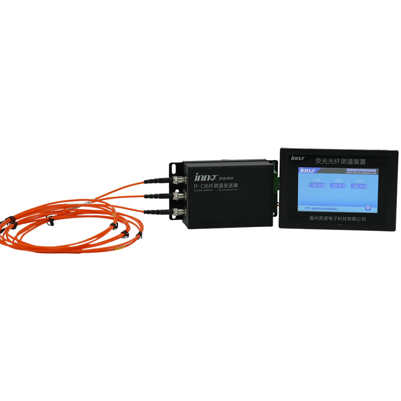
Battery Pack Fiber Optic Temperature Monitoring System
Електронна пошта: web@fjinno.net
WhatsApp: +8613599070393
Зміст
- What Is Internal Battery Temperature Monitoring?
- Why Surface-Only Monitoring Is Not Enough
- 7 Причини, чому акумуляторні батареї потребують внутрішнього моніторингу температури
- Understanding Thermal Runaway in Battery Packs
- Battery Temperature Sensor Types: Fiber Optic vs RTD vs Thermocouple vs NTC
- Key Monitoring Points in Battery Packs
- Internal Monitoring Requirements by Battery Chemistry: LFP vs NMC vs NCA
- How to Choose a Battery Temperature Monitoring System
- Battery Temperature Monitoring: Common Problems and Solutions
- Relevant International Standards for Battery Temperature Monitoring
- Real-World Application Cases
- Predictive Maintenance Based on Battery Temperature Analytics
- Future Trends in Battery Temperature Monitoring
- Часті запитання: Battery Pack Temperature Monitoring
What Is Internal Battery Temperature Monitoring?

Визначення
Internal battery temperature monitoring refers to the placement of temperature sensors at locations всередині the battery pack structure — directly on cell casings, between adjacent cells, на з'єднання шин і вкладок, і в корпусах модулів — для фіксації фактичного теплового стану батареї в режимі реального часу. Це контрастує із зовнішнім моніторингом, який вимірює лише зовнішню поверхню або температуру навколишнього середовища корпусу упаковки.
Чому це важливо
Внутрішня температура елемента батареї може відрізнятися від температури його зовнішньої поверхні на 5–20°C залежно від швидкості заряду, стан здоров'я, and cooling system effectiveness. Під час швидкої зарядки, умови зловживання, або розвиток внутрішньої несправності, ця невідповідність стає набагато більшою. Лише внутрішній моніторинг забезпечує теплову видимість, необхідну для ефективного захисту безпеки та оптимізації продуктивності.
Основні компоненти
Повна внутрішня система моніторингу складається із датчиків температури, встановлених у критичних внутрішніх місцях, середовища передачі сигналу (оптичне волокно або електричний кабель), a signal processing and demodulation unit, and a communication interface (typically RS485 Modbus RTU) for integration with the battery management system (BMS), SCADA, or facility-level energy management platform.
Why Surface-Only Monitoring Is Not Enough
Thermal Lag
Surface-mounted sensors respond to internal thermal events only after heat has conducted through the cell casing and module housing to reach the sensor location. This introduces a delay of seconds to minutes — a critical time gap during which a developing thermal runaway event can accelerate beyond the point of intervention.
Temperature Gradient Blindness
Battery packs contain significant internal temperature gradients. Cells in the center of a densely packed module can operate 10–15°C hotter than cells at the module edge. Surface-only monitoring typically captures only the cooler peripheral temperature, створюючи помилкове відчуття безпеки, тоді як внутрішні камери можуть наближатися до небезпечних меж.
Невидимість точки підключення
Шинні з'єднання, вкладки клітинок, і зварні з’єднання всередині акумуляторної батареї є типовими місцями резистентного нагрівання, спричиненого погіршеними з’єднаннями, корозії, або виробничі дефекти. Ці гарячі точки невидимі для зовнішніх поверхневих датчиків, але безпосередньо виявляються внутрішніми волоконно-оптичні датчики температури розміщені в цих точках підключення або поблизу них.
Оцінка системи охолодження
Без даних про внутрішню температуру в кількох місцях упаковки, неможливо точно оцінити, чи система охолодження підтримує прийнятну однорідність температури в усіх камерах. Нерівномірне охолодження викликає нерівномірне старіння, ємність зникає, і підвищений ризик локалізованих термічних подій — все це невидимо лише для зовнішнього моніторингу.
7 Причини, чому акумуляторні батареї потребують внутрішнього моніторингу температури

Reason 1: Раннє виявлення теплової втечі
Теплова втеча в літій-іонних елементах починається з підвищення внутрішньої температури лише на 1–5 °C вище норми, часто викликане внутрішнім коротким замиканням або розростанням дендритів. До того часу це тепло проводить до зовнішньої поверхні, внутрішня реакція, можливо, вже стала самопідтримуваною. Внутрішні датчики виявляють саму ранню стадію теплової екскурсії — коли подію ще можна зупинити за допомогою ізоляції модуля, cooling activation, або контрольований розряд. Ця можливість раннього виявлення є єдиною найважливішою причиною внутрішнього моніторингу, і це причина того волоконно-оптичні системи моніторингу температури дедалі частіше застосовуються для важливих для безпеки застосувань акумуляторів.
Reason 2: Точне термокартування для оптимізації продуктивності
На продуктивність акумуляторної батареї безпосередньо впливає однорідність температури. Cells operating at different temperatures age at different rates, deliver different capacities, and exhibit different internal resistance characteristics. Internal multi-point monitoring creates a real-time thermal map of the entire pack, enabling the BMS to balance charge distribution, adjust cooling, and optimize C-rate limits to maximize both performance and cycle life across every cell in the pack.
Reason 3: Preventing Thermal Propagation Between Cells
In a densely packed battery module, cells are separated by only millimetres. If one cell enters thermal runaway, heat transfers to adjacent cells through conduction, конвекція, and radiation — potentially triggering a cascade that destroys the entire module or pack within minutes. Internal sensors positioned between cells detect the temperature spike at the propagation boundary, giving the protection system the maximum possible time to isolate the affected area and activate fire suppression before the chain reaction establishes.
Reason 4: Connection and Busbar Hotspot Detection
High-current connections within battery packs — including cell tabs, welded joints, bolted busbars, and module-to-module interconnects — are vulnerable to resistance heating from loose connections, корозії, or weld defects. A connection that appears mechanically sound may still develop elevated resistance over time. Internal temperature monitoring at these critical junction points provides continuous hotspot surveillance, detecting developing faults long before they progress to arcing, melting, or fire. The same monitoring principle is used in контроль температури розподільних пристроїв for identical reasons.
Reason 5: Extended Battery Cycle Life and Reduced Degradation
Деградація літій-іонної батареї залежить від добре задокументованої температурної залежності. На кожні 10°C підвищення середньої робочої температури вище оптимальної, календарне старіння значно прискорюється, а термін служби циклу може скорочуватися на 30–50%. Внутрішній моніторинг дозволяє BMS підтримувати кожну комірку в межах оптимального температурного вікна, а не лише середню температуру пакета, регулюючи охолодження, обмеження потужності, і профілі заряду, засновані на фактичних внутрішніх теплових умовах, а не на оціночних або виміряних на поверхні значень.
Reason 6: Відповідність вимогам безпеки та сертифікації
Міжнародні стандарти безпеки, включаючи UL 9540A, NFPA 855, IEC 62619, та ООН 38.3 встановлюють дедалі суворіші вимоги до управління температурою батареї та моніторингу. Insurance underwriters and grid operators require documented evidence of comprehensive thermal protection. Internal temperature monitoring with traceable accuracy specifications — such as the ±0.5°C accuracy delivered by флуоресцентні волоконно-оптичні датчики температури — provides the monitoring capability and data trail that satisfies these regulatory, insurance, and certification requirements.
Reason 7: Reduced Total Cost of Ownership
While internal monitoring systems require initial investment, the total cost of ownership is substantially lower than the cost of battery failures, warranty claims, незапланований простой, fire damage, and accelerated cell replacement caused by inadequate thermal management. Fluorescent fiber optic monitoring systems require zero maintenance, без повторного калібрування, and no sensor replacement over a 25+ Річний термін служби — повне виключення регулярних витрат на технічне обслуговування та забезпечення найнижчої вартості життєвого циклу серед будь-яких технологій моніторингу, доступних для батарейних додатків.
Understanding Thermal Runaway in Battery Packs
Що таке Thermal Runaway?
Теплова реакція — це самопідсилювальна екзотермічна реакція в літій-іонному елементі, яка виникає, коли внутрішня температура перевищує залежний від хімії критичний поріг — зазвичай між 130°C і 250°C. Після початку, реакція генерує тепло швидше, ніж воно може бути видалено, підвищення температури та ініціювання розкладання електроліту, сепаратор, і електродні матеріали. В результаті відбувається бурхливе виділення газу, викид полум'я, і потенційний вибух.
Стадії теплової втечі
Stage 1 — Початкове теплогенерування (Виявляється за допомогою внутрішнього моніторингу)
An abnormal condition — internal dendrite short circuit, overcharge, механічні пошкодження, or localized cooling failure — causes a gradual internal temperature rise of 1–5°C above normal. This is the critical detection window. Internal fiber optic sensors can identify this deviation; external surface sensors typically cannot.
Stage 2 — Accelerating Reaction (Intervention Window)
As internal cell temperature exceeds 80–120°C, the solid electrolyte interphase (SEI) layer begins to decompose, releasing additional heat. The reaction becomes self-sustaining. А волоконно-оптична система контролю температури with sub-second response time can detect this acceleration and trigger protective actions — module disconnection, enhanced cooling, or emergency discharge.
Stage 3 — Full Thermal Runaway (Containment Only)
Once the critical threshold is exceeded, violent venting, вогонь, and potential explosion occur. Heat radiates to adjacent cells, potentially triggering cascading failure. At this stage, prevention is no longer possible — only containment. The objective of internal monitoring is to ensure that intervention always occurs at Stage 1 or early Stage 2.
Chemistry-Dependent Thermal Runaway Onset Temperatures
| Battery Chemistry | Thermal Runaway Onset Temperature | Relative Severity |
|---|---|---|
| NCA (Nickel Cobalt Aluminium) | ~150°C | High — rapid energy release |
| NMC (Nickel Manganese Cobalt) | ~200°C | High — significant gas generation |
| LFP (Lithium Iron Phosphate) | ~270°C | Moderate — slower onset, lower energy |
| LTO (Lithium Titanate) | >280°C | Low — most thermally stable |
Battery Temperature Sensor Types: Fiber Optic vs RTD vs Thermocouple vs NTC

Choosing the right sensor technology for internal battery temperature monitoring carries direct safety implications. The four main technologies differ significantly in accuracy, electromagnetic interference (EMI) immunity, short-circuit risk, and suitability for internal placement within battery packs.
| Особливість | Fluorescent Fiber Optic Sensor | NTC Thermistor | RTD (Pt100 / Pt1000) | Термопара (Type K/J) |
|---|---|---|---|---|
| Точність вимірювання | ±0.1 – 0.5°C | ±1 – 2°C | ±0.5 – 1°C | ±1 – 2°C |
| EMI / High Voltage Immunity | ✅ Fully immune (no metal, діелектрик) | ⚠️ Partial (susceptible to noise) | ❌ Susceptible (requires shielding) | ❌ Susceptible (requires shielding) |
| Short-Circuit Risk Inside Battery | ✅ Zero (повністю діелектрик) | ❌ Present (metallic leads) | ❌ Present (metallic element) | ❌ Present (metallic junction) |
| Internal Cell/Module Placement | ✅ Safe (no conductive path) | ⚠️ Surface only recommended | ❌ Unsafe for internal placement | ❌ Unsafe for internal placement |
| Час відгуку | < 1 другий | 1–5 seconds | 2– 10 секунд | 1–3 seconds |
| Operating Temperature Range | -40°C to +260°C | -40°C до +150 °C | -200°C до +600 °C | -200°C to +1350°C |
| Довгострокова стабільність | ✅ Excellent (no drift) | ⚠️ Помірно (drift over time) | ✅ Good | ⚠️ Помірно (prone to drift) |
| Maintenance Requirement | ✅ Maintenance-free | Periodic replacement | Periodic calibration | Frequent calibration |
| Багатоточкова здатність | ✅ Up to 64 каналів на одиницю | Limited by wiring complexity | Separate sensor per point | Separate sensor per point |
| Термін служби | > 25 років | 3–5 years | 5–10 years | 2–5 years |
| Загальна вартість володіння | ✅ Lowest (no calibration/replacement) | Помірний | Помірний | Вища (frequent replacement) |
| Кращий додаток | Internal cell/module monitoring, safety-critical packs | Low-cost BMS integration, surface monitoring | External oil/ambient monitoring | Low-cost auxiliary monitoring |
Висновок: For internal placement within battery packs where short-circuit risk must be eliminated and EMI immunity is essential, fluorescent fiber optic sensors are the superior choice. NTC thermistors remain practical for surface-mounted BMS integration in cost-sensitive applications where the limitations are understood and accepted. For a detailed technical comparison across all sensor types, refer to the fiber optic temperature measurement system FAQ.
Key Monitoring Points in Battery Packs
Individual Cell Surface
The most critical monitoring location is directly on the cell casing at the point of highest thermal stress. For prismatic and pouch cells, this is typically the center of the largest face. For cylindrical cells, sensors are placed on the cell body near the positive terminal where internal current collector resistance generates the most heat.
Inter-Cell Gap
Placing sensors between adjacent cells captures the thermal boundary condition that determines whether heat from a failing cell will propagate to its neighbours. This is the most important location for thermal propagation prevention.
Cell Tab and Busbar Connections
Welded cell tabs, bolted busbars, and module interconnects are susceptible to resistance heating from degraded connections. Monitoring these points provides early warning of developing connection faults — applying the same principle used in fiber optic temperature monitoring for switchgear and high-voltage electrical connections.
Module Core (Center of Pack)
The geometric center of a battery module or pack is the location furthest from any cooling surface. It consistently operates at the highest temperature under load and is the most likely location for thermal accumulation to reach dangerous levels.
Cooling Circuit Inlet and Outlet
Temperature sensors at cooling system inlet and outlet measure the temperature differential across the cooling circuit. A narrowing differential indicates degraded cooling capacity — an early warning that the thermal management system is losing effectiveness.
Pack Enclosure Ambient
Ambient temperature inside the battery enclosure establishes the thermal baseline against which all cell and module temperatures are compared. An individual module reading that diverges significantly from the enclosure ambient — even if still within absolute limits — may indicate the early stages of an internal fault.
Internal Monitoring Requirements by Battery Chemistry: LFP vs NMC vs NCA
The thermal behavior and monitoring requirements differ significantly between lithium-ion battery chemistries. Understanding these differences is essential for specifying the correct monitoring system configuration.
| Параметр | LFP (LiFePO₄) | NMC (LiNiMnCoO₂) | NCA (LiNiCoAlO₂) |
|---|---|---|---|
| Thermal Runaway Onset | ~270°C | ~200°C | ~150°C |
| Energy Release During Runaway | Нижній | Високий | Дуже висока |
| Propagation Risk | Нижній (but not zero) | Високий | Дуже висока |
| Normal Operating Range | 15–45°C | 15–45°C | 15–40°C |
| Recommended Alarm Threshold | 55–60°C | 50–55°C | 45–50°C |
| Recommended Trip Threshold | 70–80°C | 60–70°C | 55–65°C |
| Minimum Monitoring Density | Per module | Per module (per cell for critical applications) | Per cell recommended |
| Internal Monitoring Priority | Високий | Дуже висока | Критичний |
Висновок: У той час як хімічний склад LFP забезпечує вищу термічну стабільність, всі літій-іонні хімікати виграють від контролю внутрішньої температури. Хімії NMC і NCA — з нижчою температурою початку розбігу тепла та вищою енергією розповсюдження — вимагають найвищої щільності моніторингу та найшвидшого часу відгуку датчика, виготовлення волоконно-оптичні датчики температури краща технологія для цих хімікатів.
How to Choose a Battery Temperature Monitoring System


Вибір правильної системи моніторингу вимагає оцінки хімічного складу батареї, архітектура пакета, критичність програми, and integration requirements. Дотримуйтеся цього покрокового посібника, щоб зробити оптимальний вибір.
Крок 1: Визначте хімічний склад батареї та форм-фактор елемента
Визначте, чи використовує ваш акумулятор LFP, NMC, NCA, LTO, або інша хімія. Визначте форму клітини — циліндрична (напр., 2170, 4680), призматичний, або мішок. Хімія визначає порогові значення тривоги та спрацьовування, while the form factor determines probe geometry and placement strategy.
Крок 2: Define the Application Criticality and Safety Requirements
Assess the consequence of a thermal event in your application. Grid-scale energy storage, electric vehicles, авіації, and maritime applications carry the highest safety requirements and justify per-cell or per-module internal monitoring with the highest-accuracy sensor technology available. Lower-criticality applications such as residential storage may accept per-module monitoring with cost-optimized sensors.
Крок 3: Determine the Number of Monitoring Points
A minimum configuration includes one sensor per module plus busbar monitoring. Advanced configurations add per-cell monitoring, inter-cell gap sensors, cooling circuit sensors, and enclosure ambient monitoring. Багатоканальний fluorescent fiber optic temperature measurement devices підтримка 1 до 64 каналів на одиницю, allowing precise system sizing for any pack architecture.
Крок 4: Evaluate Sensor Technology for Internal Placement Safety
For any sensor placed inside the battery pack — between cells, on busbars, or near cell tabs — the sensor must not introduce a short-circuit risk. This requirement eliminates all metallic sensor technologies (NTC, RTD, thermocouple) from consideration for true internal placement. Only fully dielectric fiber optic sensors can be safely installed inside battery packs without creating a conductive path between cells or conductors.
Крок 5: Assess BMS Communication and Integration Requirements
Determine the communication protocol required by your BMS or SCADA system. INNO fiber optic monitoring systems output data via RS485 Modbus RTU — the most widely supported industrial protocol. Підтвердьте сумісність із вашою існуючою архітектурою збору даних BMS і системою керування сигналізацією.
Крок 6: Розгляньте спосіб встановлення — заводський або модернізований
Для нових конструкцій акумуляторних батарей, волоконно-оптичні датчики можна інтегрувати під час виробництва для оптимального розміщення та найвищої точності моніторингу. Для існуючих акумуляторних установок, варіанти модернізації датчиків дозволяють прокладати зонди через існуючі шляхи управління кабелями та встановлювати їх між модулями або на доступних з’єднаннях шин під час планового технічного обслуговування.
Крок 7: Перевірте відповідність стандартам і спроможність постачальника
Переконайтеся, що система моніторингу відповідає застосовним стандартам (УЛ 9540, NFPA 855, IEC 62619, І 38.3). Оцініть можливості OEM/ODM виробника датчика, досвід проектування спеціального зонда, і послужний список у застосуванні акумуляторів. As a dedicated fiber optic temperature sensor manufacturer, INNO надає спеціальні геометрії зондів, private-label transmitters, and firmware customization for battery pack OEM integration.
Battery Temperature Monitoring: Common Problems and Solutions
When a battery temperature alarm activates or readings appear abnormal, rapid diagnosis is essential to prevent equipment damage or safety incidents. The following guide covers the most common problems encountered in battery temperature monitoring systems.
Problem 1: Temperature Alarm Activates Under Normal Charge/Discharge Conditions
Possible Causes:
- Cooling system malfunction — blocked airflow, failed fans, or degraded coolant flow rate
- Ambient temperature significantly higher than the system’s rated operating environment
- Battery pack operating at sustained C-rate above design limits
- Uneven cell balancing causing individual cells to work harder
- Internal cell degradation increasing internal resistance and heat generation
Recommended Action: Check cooling system operation first. Перевірте фактичну швидкість заряду/розряду C відповідно до специфікацій упаковки. Порівняйте температури окремих клітин, щоб визначити нерівномірно завантажені або пошкоджені клітини. Якщо охолодження працює і навантаження відповідає номіналу, провести тестування імпедансу тривожних клітин для оцінки стану здоров'я.
Problem 2: Датчик температури показує аномально високий або низький рівень
Possible Causes:
- Розрив ланцюга термістора NTC (читання стрибає до максимуму) або коротке замикання (читається мінімум)
- Фізичне пошкодження оптоволоконного кабелю (вигин за мінімальний радіус, crushing)
- Послаблене з’єднання на клемі датчика або вході контролера
- Збій вхідного каналу контролера
Recommended Action: For NTC thermistors, виміряйте опір на клемах датчика мультиметром і порівняйте з таблицею опору-температури виробника. For fiber optic sensors, перевірте рівень оптичної потужності та скористайтеся вбудованою функцією самодіагностики контролера. Replace damaged sensors or repair cables as needed.
Problem 3: Inconsistent Temperature Readings Between Adjacent Cells
Possible Causes:
- Uneven cooling airflow or coolant distribution within the module
- Cell-to-cell state of health variation causing different heat generation rates
- Sensor placement inconsistency — sensors not at equivalent thermal positions on each cell
- Individual cell internal fault developing (early stage thermal anomaly)
Recommended Action: Verify sensor placement consistency. Check cooling system flow distribution. If thermal asymmetry persists after eliminating sensor and cooling issues, isolate and test the affected cells for internal impedance and capacity. Persistent unexplained temperature divergence may indicate an early-stage internal fault requiring cell replacement.
Problem 4: Intermittent False Alarms in High-EMI Environments
Possible Causes:
- Electrical noise on NTC or RTD sensor cables caused by inverter switching, motor drives, or high-current conductors
- Loose terminal connections causing momentary signal interruption
- Alarm threshold set too close to normal operating temperature
Recommended Action: Inspect and tighten all terminal connections. Replace unshielded sensor cables with shielded twisted-pair routed away from power conductors. Review and adjust alarm thresholds with adequate margin. For persistent EMI-related false alarms, оновлення до волоконно-оптичних датчиків, which are inherently immune to all electromagnetic interference.
Problem 5: Cooling System Does Not Activate at Set Temperature Threshold
Possible Causes:
- BMS cooling control relay or output channel failure
- Wiring fault between BMS output and fan/pump contactor
- Fan motor or coolant pump failure
- Incorrect activation threshold programmed in the BMS
Recommended Action: Test the BMS relay output while manually simulating an overtemperature condition. Verify wiring continuity to the cooling equipment. Test the fan or pump independently by applying rated voltage directly. Confirm programmed activation threshold matches the thermal management design specification.
Problem 6: Temperature Readings Drift Over Time Without Apparent Cause
Possible Causes:
- NTC thermistor aging and resistance drift after sustained elevated temperature operation
- Thermocouple junction degradation
- Sensor mounting loosening — thermal contact between sensor and cell surface degrading
Recommended Action: Compare drifting sensor readings against a calibrated reference thermometer. Re-torque or re-bond sensor mounting. If drift is confirmed as a sensor issue, replace the sensor. Fluorescent fiber optic sensors operate on a photophysical principle that is inherently immune to calibration drift — the factory calibration remains valid for the sensor’s entire service life of 25+ років.
Relevant International Standards for Battery Temperature Monitoring
УЛ 9540 — Energy Storage Systems and Equipment
УЛ 9540 addresses the safety of energy storage systems, including requirements for thermal management and continuous monitoring of battery operating parameters. Compliance requires demonstration that the monitoring system can detect abnormal thermal conditions and initiate protective actions within defined response times.
UL 9540A — Test Method for Evaluating Thermal Runaway Fire Propagation in Battery Energy Storage Systems
UL 9540A specifically evaluates whether thermal runaway in a single cell propagates to adjacent cells, модулі, or beyond the ESS enclosure. Internal temperature monitoring data is critical for validating thermal runaway mitigation strategies during UL 9540A testing and for documenting ongoing operational compliance.
NFPA 855 — Standard for the Installation of Stationary Energy Storage Systems
NFPA 855 requires continuous monitoring of battery system operating parameters including temperature, with automated protective actions when parameters exceed safe limits. Internal fiber optic monitoring satisfies these requirements with higher accuracy and faster response than conventional surface-mounted sensor technologies.
IEC 62619 — Secondary Cells and Batteries — Safety Requirements for Secondary Lithium Cells and Batteries for Use in Industrial Applications
IEC 62619 defines safety requirements for lithium batteries in industrial applications including energy storage. Стандарт вимагає терморегулювання та моніторингу, включаючи здатність виявляти аномальні температурні умови та реагувати на них на рівні комірки та модуля.
IEC 63056 — Вторинні літієві елементи та батареї для використання в системах зберігання електроенергії
IEC 63056 спеціально стосується літієвих батарей для стаціонарного зберігання енергії, з вимогами постійного теплового моніторингу, системи сигналізації та захисту, та документація ефективності теплового менеджменту протягом терміну експлуатації системи.
І 38.3 — Перевезення небезпечних вантажів: Тестування літієвої батареї
І 38.3 визначає перевірку безпеки літієвих батарей під час транспортування, включаючи випробування на термічну дію. Дані внутрішньої температури від волоконно-оптичних датчиків під час ООН 38.3 testing provides the precise thermal characterization data needed for battery safety certification and transport documentation.
IEEE 1679.1 — Guide for the Characterization and Evaluation of Lithium-Based Batteries in Stationary Applications
IEEE 1679.1 provides evaluation guidance for lithium battery performance in stationary applications, including thermal characterization requirements. Internal temperature monitoring data supports the thermal performance assessment and life prediction analyses defined in this standard.
Real-World Application Cases
Кейс-стаді 1: 200 MWh Grid-Scale Energy Storage Facility — Thermal Runaway Prevention
Фон програми
A utility-scale BESS facility with NMC chemistry battery cabinets required comprehensive thermal monitoring to satisfy both insurance underwriter requirements and local fire safety codes. Оригінальна система моніторингу на основі термісторів надавала лише дані про температуру поверхні з часом відгуку 3–5 секунд.
Рішення реалізовано
Багатоканальний волоконно-оптичні системи моніторингу температури були розгорнуті по всіх шафах для зберігання. Кожна шафа отримала помодульний внутрішній моніторинг, а також моніторинг підключення шин. Дані про температуру були інтегровані з BMS підприємства через RS485 Modbus RTU та передані на центральну платформу SCADA.
Досягнуті результати
Протягом першого року експлуатації, система виявила теплову аномалію на рівні модуля — підвищення температури на 4°C над сусідніми модулями за ідентичних умов навантаження. Дослідження виявило частково пошкоджений канал охолодження в ураженому модулі. Модуль був ізольований і відремонтований під час планового технічного обслуговування. The anomaly would have been undetectable by the original surface-mounted thermistor system until the temperature deviation reached 15°C or more — by which time intervention options would have been severely limited.
Кейс-стаді 2: EV Battery Pack Development — Fast-Charge Thermal Optimization
Фон програми
A leading EV manufacturer required cell-level internal temperature data during extreme fast-charging (XFC) development testing. Existing NTC-based monitoring could not provide the accuracy or internal placement needed to characterize thermal gradients within the pack during 350 kW charging events.
Рішення реалізовано
Custom-geometry волоконно-оптичні датчики температури з 2 mm diameter were integrated between cells and on busbar connections throughout a test battery pack. The probes were connected to a multi-channel fiber optic transmitter, with data logged at 1-second intervals during charging cycles.
Досягнуті результати
The internal temperature data revealed that center cells in the pack reached temperatures 18°C higher than edge cells during 350 kW charging — a gradient invisible to the pack’s production NTC sensors mounted on external module surfaces. The thermal data enabled the engineering team to redesign the cooling plate geometry, reducing the center-to-edge temperature differential to under 5°C and enabling a 15% increase in maximum sustained charging power without exceeding cell temperature limits.
Кейс-стаді 3: Containerised ESS — Retrofit Monitoring Upgrade
Фон програми
An operator of containerised LFP battery storage systems required a monitoring upgrade to comply with updated local fire safety regulations. The existing monitoring consisted of ambient temperature sensors and external module surface thermistors — insufficient to meet the new per-module internal monitoring requirements.
Рішення реалізовано
Slim fiber optic probes were retrofitted between battery modules and on high-current busbar connections during a scheduled maintenance window. No structural modification of the battery modules was required. The флуоресцентний волоконно-оптичний прилад для вимірювання температури was installed in the cabinet’s existing equipment bay and connected to the site BMS.
Досягнуті результати
The retrofit was completed in under 4 hours per container with no battery system downtime. The operator achieved full compliance with updated fire safety regulations and received an improved risk assessment from their insurance underwriter. Over two years of post-retrofit operation, система виявила три випадки підвищення температури з’єднання шин, все вирішено під час планового технічного обслуговування до того, як сталася будь-яка подія безпеки.
Predictive Maintenance Based on Battery Temperature Analytics
Condition Assessment
Історичні дані та дані про внутрішню температуру в реальному часі аналізуються для оцінки швидкості деградації клітин, cooling system effectiveness, і взаємозв'язок між схемами навантаження та термічним стресом. Комірки, які стабільно працюють при вищих температурах, ніж їхні сусіди — навіть з невеликим запасом — можуть бути визначені як кандидати на ранню заміну або ребалансування.
Failure Prediction
Удосконалені алгоритми розпізнають аномальні температурні моделі, включаючи поступовий дрейф базової лінії (вказує на збільшення внутрішнього опору), різкі скачки температури (вказує на розвиток внутрішнього короткого замикання), і теплові аномалії, пов'язані з навантаженням (вказує на погіршення зв'язку). These patterns predict potential failures days or weeks before they would cause an operational event.
Оптимізація обслуговування
Data-driven insights allow maintenance to be scheduled based on actual asset condition rather than fixed time intervals. Cells and modules are replaced only when their thermal data indicates genuine degradation, eliminating unnecessary interventions and maximizing the useful life of every component in the pack.
Cost Reduction
Predictive maintenance driven by internal temperature analytics reduces emergency repairs, незапланований простой, warranty claims, and total operating costs. The investment in comprehensive internal monitoring is typically recovered within the first prevented incident.
Future Trends in Battery Temperature Monitoring
Digital Integration
Growing use of cloud-based analytics, цифрові близнюки, and artificial intelligence for battery fleet management based on internal temperature and other sensor data. Real-time thermal models updated with actual internal temperature measurements enable dynamic optimization of charge profiles, cooling strategies, and end-of-life predictions.
Sensor Miniaturization
Advances in fiber optic sensor design are delivering thinner probes, flexible form factors, and simplified installation methods that enable internal monitoring in increasingly dense pack architectures — including the tight packaging requirements of next-generation EV battery platforms.
Multi-Parameter Integration
Next-generation monitoring platforms combine internal temperature with impedance spectroscopy, strain sensing, and gas detection within a single integrated system, providing a more complete picture of cell health from a unified sensor and data platform.
Embedded Sensors in Cell Manufacturing
The long-term trend points toward temperature sensors embedded directly within the cell during manufacturing — providing the most accurate possible internal temperature data. Волоконно-оптичні датчики, with their dielectric construction and zero interference characteristics, are uniquely suited for this embedded application.
Standardization and Regulatory Evolution
International standards bodies are moving toward mandatory internal temperature monitoring requirements for safety-critical battery applications. Early adoption of internal monitoring positions manufacturers and operators ahead of these evolving regulatory requirements.
Часті запитання: Battery Pack Temperature Monitoring
What is the difference between internal and external battery temperature monitoring?
External monitoring places sensors on the outside surface of the battery module casing or in the ambient air around the pack. Внутрішній моніторинг розміщує датчики безпосередньо на поверхні клітин, між клітинами, on busbars, і в структурі модуля. Внутрішній моніторинг виявляє температурні аномалії на 5–15°C раніше та від секунд до хвилин швидше, ніж зовнішній моніторинг, забезпечуючи час відгуку, необхідний для запобігання розповсюдженню теплових розбігів. Для важливих для безпеки додатків, внутрішній моніторинг с волоконно-оптичні датчики температури настійно рекомендується.
Чому я не можу просто використовувати термістори NTC для моніторингу внутрішньої батареї?
NTC-термістори мають металеві дроти, які створюють потенційний шлях електричного короткого замикання, якщо їх розмістити всередині акумуляторної батареї між елементами або поблизу високовольтних провідників. У середовищі, де коротке замикання може спровокувати витік тепла, якому датчик призначений для запобігання, цей ризик принципово неприйнятний. NTC thermistors are appropriate for external surface mounting only. For true internal placement, повністю діелектрик флуоресцентні волоконно-оптичні датчики are the only technology that eliminates short-circuit risk entirely.
How many monitoring points does a battery pack need?
The minimum recommendation is one monitoring point per battery module plus sensors on major busbar connections. For higher-risk chemistries (NMC, NCA) or safety-critical applications (grid-scale ESS, electric vehicles, авіації), per-cell monitoring is recommended. Additional sensors should be placed at cooling circuit inlet/outlet and enclosure ambient positions. INNO’s multi-channel fiber optic transmitters support 1 до 64 каналів на одиницю, allowing precise system sizing for any pack architecture.
Can fiber optic temperature sensors be retrofitted to existing battery packs?
так. The slim 2–3 mm diameter of fiber optic probes allows them to be routed through existing cable management paths and installed between modules or on busbar connections during scheduled maintenance. No structural modification of the battery modules is required. Retrofit installations provide significantly improved monitoring compared to original surface-mounted sensors.
What is the response time of fiber optic temperature sensors for battery monitoring?
The response time is less than 1 second — fast enough to detect the rapid temperature excursions that characterize the early stages of thermal runaway in lithium-ion cells. This is significantly faster than the 2–10 second response typical of RTD sensors and 1–5 second response of NTC thermistors, particularly when those sensors are surface-mounted rather than internally placed.
Do fiber optic sensors work with all battery chemistries?
так. Fiber optic monitoring is compatible with all commercial lithium-ion chemistries including LFP, NMC, NCA, and LTO, as well as sodium-ion, solid-state, and other emerging battery technologies. The probe materials are chemically inert and unaffected by battery electrolytes or off-gases.
How does internal temperature data integrate with the BMS?
All INNO fluorescent fiber optic temperature measurement devices output data via RS485 Modbus RTU. The BMS reads temperature data from each monitoring channel in real time and uses it to manage cooling activation, charge/discharge rate limiting, cell balancing, module isolation, and alarm/protection logic. Integration requires only standard Modbus register mapping in the BMS software.
Does internal temperature monitoring help with battery warranty and insurance?
так. Comprehensive internal temperature data provides documented evidence that the battery system has been operated within its specified thermal limits throughout its service life. This data supports warranty claims by proving that thermal damage was not caused by operator abuse. Insurance underwriters increasingly recognize internal monitoring as a risk mitigation measure, which can improve facility risk profiles and reduce premiums.
What happens if a fiber optic probe is damaged inside the battery pack?
A damaged fiber optic probe is inherently safe — it cannot cause a short circuit, spark, or any electrical hazard because it contains no metal and carries no electrical current. Функція самодіагностики системи моніторингу виявляє втрату оптичного сигналу з пошкодженого каналу та генерує сигнал про несправність датчика. Пошкоджений зонд можна замінити під час наступного вікна планового технічного обслуговування без екстреного втручання.
Як отримати пропозицію щодо системи моніторингу температури акумуляторної батареї?
Зв’яжіться з групою розробки додатків INNO www.fjinno.net з деталями вашого проекту, включаючи хімію батареї, фактор форми клітини, кількість модулів, архітектура пакета, Вимоги до зв’язку BMS, і чи є інсталяція новою інтеграцією дизайну чи модернізацією. Цінова пропозиція для конкретного проекту, включаючи рекомендації щодо геометрії зонда, конфігурація каналу, і вартість системи зазвичай надається в межах 24 години.
Відмова від відповідальності: Всі технічні характеристики товару, приклади застосування, результати справи, і сторонні посилання в цій статті призначені лише для загальної інформації та можуть бути оновлені без попередження. Фактичні характеристики продукту залежать від умов встановлення, операційне середовище, and system configuration. Торгові марки, посилання на стандарти, та галузеві терміни належать їхнім відповідним власникам і використовуються лише для опису; жодна приналежність чи підтримка не мається на увазі. Будь ласка, зв’яжіться з відділом продажів INNO для офіційної угоди, пропозиція щодо конкретного проекту та технічне підтвердження перед покупкою. © 2011–2026 Fuzhou Innovation Electronic Scie&Tech Co., ТОВ. Всі права захищено.

Оптоволоконний датчик температури, Інтелектуальна система моніторингу, Розповсюджений виробник оптоволокна в Китаї
 |
 |
 |