 INNO fiber optik sıcaklık sensörleri ,sıcaklık izleme sistemleri.
- Trafo sıcaklığı izleme continuously tracks internal temperatures to prevent insulation degradation and thermal breakdown that lead to catastrophic equipment failure
- Hot spot temperatures in transformer windings typically run 10-15°C higher than top oil temperature and represent the most critical measurement point for assessing transformer health
- Fiber optik sıcaklık sensörleri provide superior accuracy (±1°C), complete immunity to electromagnetic interference, and high voltage isolation up to 100kV or more
- Strategic sensor placement at winding hot spots, üst yağ, çekirdek, and bushing locations enables comprehensive thermal profiling and early fault detection
- Abnormal temperature rise serves as the primary indicator of overload conditions, soğutma sistemi arızası, or developing internal faults months before catastrophic failure occurs
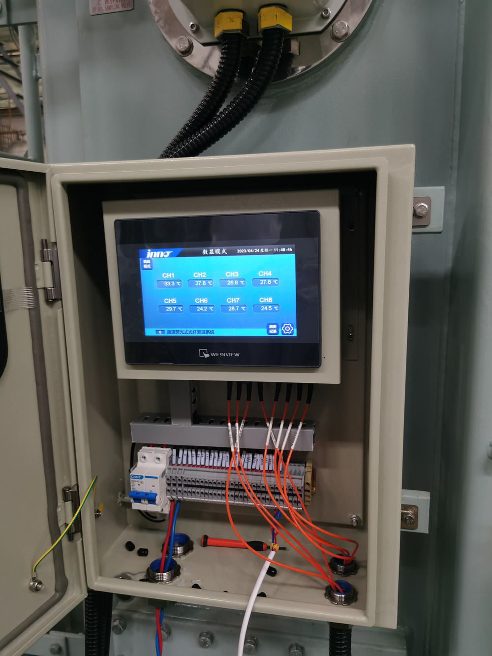
FJINNO Fluorescent Fiber Optic Temperature Monitoring System for Transformers
E-posta: web@fjinno.net
WhatsApp: +8613599070393
The FJINNO floresan fiber optik sıcaklık izleme sistemi is specifically engineered for transformer winding hot spot detection and critical thermal monitoring applications. Utilizing advanced rare-earth fluorescent crystal sensor technology, the system measures temperature by analyzing fluorescent decay time, providing immunity to electromagnetic fields, radyo frekansı girişimi, and high voltage environments that plague conventional electronic sensors.
This system represents the most reliable solution for oil-immersed transformer temperature measurement, with sensors that can be placed directly into high-voltage winding environments without any risk of electrical interference or ground loop issues. The intrinsically safe design requires no electrical power at the sensor point, eliminating explosion risks and enabling installation in the most demanding power system applications.
Teknik Özellikler
| Parametre | Şartname |
|---|---|
| Sıcaklık Aralığı | -40°C ila +260°C |
| Ölçüm Doğruluğu | ±1°C (0 200°C'ye kadar) |
| Çözünürlük | 0.1°C |
| Tepki Süresi | < 2 saniye |
| Gerilim İzolasyonu | > 100kV |
| EMI Bağışıklığı | Tamamlamak (fiber optik) |
| Kanal Kapasitesi | 1 ile 32 birim başına kanallar |
| Sensör Çapı | 2.5mm (standard probe) |
| IP Rating | IP65 (controller enclosure) |
| İletişim | RS485, ethernet, 4-20mA |
Kurulum ve Uygulama
Sensor Placement Guidelines:
For oil-immersed power transformers, floresan fiber optik problar should be installed at the following critical locations:
- Directly embedded in the hottest point of high-voltage and low-voltage windings (typically the top disk of the innermost winding)
- Top oil temperature location in the conservator tank or main tank dome
- Çekirdek sıcaklığı izleme (for large units)
- Bushing base connections where contact resistance heating may occur
- Load tap changer (LTC) compartment for contact monitoring
The fiber optik kablolar pass through the transformer bushings or dedicated fiber optic feedthroughs, maintaining complete electrical isolation. Each probe is hermetically sealed and designed for permanent installation with 30+ yıl servis ömrü.
System Features
| Özellik | Fayda |
|---|---|
| Multi-channel monitoring | Simultaneous measurement of up to 32 points from a single controller |
| Real-time alarming | Programmable high/low temperature alarms with relay outputs |
| Trend recording | Continuous data logging with configurable sample rates |
| SCADA entegrasyonu | Standard protocols for substation automation systems |
| Hot spot calculation | Automatic thermal gradient analysis and winding hot spot estimation |
| Bakım gerektirmeyen çalışma | No calibration required, drift-free measurement over decades |
Bakım ve Önlemler

Important Operating Notes:
- The fiber optik sıcaklık sensörü probes require no maintenance and should never be removed from the transformer during routine service
- Avoid sharp bending (radius < 25mm) of the fiber optic cables during installation to prevent signal loss
- Controller units should be mounted in temperature-controlled environments when possible; extreme ambient temperatures may affect display readability
- Verify communication integrity to SCADA systems quarterly; alarm contact outputs should be tested during scheduled outages
- Sensor cables should be properly strain-relieved at the bushing entry point to prevent mechanical stress during transformer thermal cycling
- When troubleshooting, verify issues with the controller and cables before suspecting sensor probe failure, which is extremely rare
İçindekiler
- What Exactly Is Transformer Temperature Monitoring?
- Why Is Temperature Monitoring Critical for Transformer Lifespan?
- What Are the Primary Heat Generation Sources in Power Transformers?
- What Is a Hot Spot and Where Does It Occur?
- How Does Hot Spot Temperature Differ from Top Oil Temperature?
- What Are the IEEE and IEC Temperature Limits for Transformers?
- What Happens When a Transformer Overheats?
- What Are the Traditional Temperature Monitoring Methods?
- Why Are Fiber Optic Sensors Superior for Transformer Monitoring?
- How Does Fluorescent Fiber Optic Temperature Sensing Work?
- Where Should Temperature Sensors Be Strategically Placed?
- How Many Monitoring Points Are Required for Adequate Coverage?
- What Do Different Temperature Readings Indicate About Transformer Health?
- How Does Temperature Monitoring Integrate with Transformer Protection Systems?
- What Causes Abnormal Temperature Rise in Transformers?
- What Are the Warning Signs of Transformer Overheating?
- How Should Temperature Monitoring Systems Be Inspected During Routine Maintenance?
- Can Temperature Monitoring Systems Fail and What Are the Failure Modes?
- What Factors Can Cause Inaccurate Temperature Readings?
- How Do You Select the Right Temperature Monitoring System for Your Transformer?
1. What Exactly Is Trafo Sıcaklık İzleme?

Trafo sıcaklığı izleme is a continuous measurement and recording system designed to track thermal conditions within power transformers. This system comprises strategically placed sıcaklık sensörleri, data acquisition hardware, alarm mantığı, and communication interfaces that provide real-time visibility into the transformer’s thermal state.
The fundamental purpose is to ensure the transformer operates within safe thermal limits at all times. The system monitors multiple temperature points including winding hot spots, üst yağ sıcaklığı, alt yağ sıcaklığı, and in some cases, core temperature and bushing connections. Modern systems provide not just instantaneous readings but also historical trending, thermal gradient analysis, and predictive alarm capabilities.
Unlike simple temperature indicators that provide only a local dial reading, kapsayıcı sıcaklık izleme sistemleri integrate with substation SCADA systems, enabling remote supervision and automated protective actions when dangerous thermal conditions develop.
2. Why Is Temperature Monitoring Critical for Transformer Lifespan?

The relationship between temperature and transformer insulation life is governed by the Arrhenius equation, which demonstrates that insulation aging is an exponential function of temperature. The widely accepted industry rule states that for every 8°C increase above the rated temperature, yalıtımın eskime oranı iki katına çıkar, effectively cutting the transformer’s expected service life in half.
Transformer insulation systems, whether kraft paper in oil-immersed units or epoxy resin in dry-type transformers, undergo irreversible chemical degradation when exposed to heat. This degradation manifests as reduced dielectric strength, increased brittleness, and eventual mechanical failure. A transformer designed for a 30-year service life operating consistently 16°C above its thermal rating may fail in as little as 7-8 yıllar.
| Operating Temperature Above Rating | Insulation Life Impact | Expected Service Life (from 30 years baseline) |
|---|---|---|
| 0°C (at rating) | Normal aging rate | 30 yıllar |
| +8°C | 2× aging acceleration | 15 yıllar |
| +16°C | 4× aging acceleration | 7.5 yıllar |
| +24°C | 8× aging acceleration | 3.75 yıllar |
| -8°C (under rating) | 0.5× aging (hayat uzatma) | 60 yıllar |
Beyond chronic overheating, acute thermal events—such as a sudden hot spot caused by a blocked cooling duct or a high-resistance connection—can cause immediate insulation failure, leading to internal arcing and catastrophic transformer destruction. Sürekli termal izleme provides the only reliable means to detect these developing conditions before permanent damage occurs.
3. What Are the Primary Heat Generation Sources in Power Transformers?

Transformers generate heat through three fundamental loss mechanisms, each contributing to the overall thermal load that must be dissipated:
Core Losses (No-Load Losses)
Core losses occur in the magnetic steel laminations and are present whenever the transformer is energized, regardless of load current. These consist of hysteresis losses (energy required to reverse magnetic domains) and eddy current losses (circulating currents induced in the steel). Modern grain-oriented silicon steel minimizes these losses, ama yine de tipik olarak temsil ediyorlar 20-30% tam yükte toplam kayıplar ve 100% yüksüz durumdaki kayıplar. Çekirdek, hacmi boyunca nispeten eşit sıcaklıkta çalışır.
Bakır Kayıpları (Yük Kayıpları)
Sargı direnci kayıpları, genellikle I²R kayıpları veya bakır kayıpları olarak adlandırılır, yük akımının karesiyle orantılıdır. Bunlar tam yük koşullarında toplam kayıpların en büyük bileşenini temsil eder, çoğu zaman muhasebe 70-80% toplam ısı üretimi. Critically, bu kayıplar düzgün bir şekilde dağılmamıştır; akım yoğunluğunun en yüksek olduğu alanlarda en yüksektir, özellikle en içteki sarım dönüşlerinde ve kurşun bağlantılarında.
Stray Losses
Başıboş kayıplar yapısal çelik bileşenlerde girdap akımlarını tetikleyen kaçak manyetik akı nedeniyle meydana gelir (tank walls, core clamps, kravat plakaları) ve sargıların kendisinde. Bunlar açıklanabilir 10-15% of total losses and create localized hot spots in unexpected areas, particularly near high-current leads and in areas where magnetic flux is concentrated by structural geometry.
4. What Is a Hot Spot and Where Does It Occur?
The sıcak nokta is defined as the highest temperature point within the transformer winding structure. This location experiences the most severe thermal stress and determines the overall thermal rating and life expectancy of the transformer. The hot spot is not directly accessible for measurement in most designs, making its assessment a critical engineering challenge.
In typical power transformer construction, the hot spot occurs at the top of the innermost high-voltage winding. This location experiences the convergence of three unfavorable thermal conditions: maximum I²R heating (highest current density occurs in inner windings), poorest cooling circulation (oil flow is slowest at the winding interior), and heat stratification (hot oil naturally rises to the top of the winding).
Other potential hot spot locations include:
- Lead exit points where conductors transition from winding to bushing, often with higher resistance connections
- Tap winding sections where current density changes abruptly
- Blocked cooling passages created by manufacturing defects or debris accumulation
- High-current low-voltage windings near the core, particularly in shell-type designs
- Load tap changer contacts where contact resistance heating occurs
5. How Does Hot Spot Temperature Differ from Top Oil Temperature?

Arasındaki ilişki sıcak nokta sıcaklığı Ve üst yağ sıcaklığı is characterized by the hot spot gradient or hot spot rise, typically denoted as ΔθH. This gradient represents the additional temperature rise of the hottest winding point above the surrounding top oil temperature.
For mineral oil-immersed transformers designed to modern standards:
| Transformer Type/Cooling | Typical Hot Spot Rise Above Top Oil | Range at Full Load |
|---|---|---|
| ONAN (Oil Natural, Air Natural) | 15°C | 10-20°C |
| AÇIK KAPALI (Oil Natural, Air Forced) | 12°C | 8-18°C |
| OFAF (Oil Forced, Air Forced) | 10°C | 6-15°C |
| Dağıtım transformatörleri | 10-15°C | 8-20°C |
This gradient exists because oil circulation cannot perfectly equalize winding and bulk oil temperatures. The oil in direct contact with the hot winding copper absorbs heat and rises, but thermal resistance between copper and oil, combined with limited convection velocity in narrow cooling ducts, prevents complete thermal equilibrium.
En yüksek yağ sıcaklığı is measured easily at the top of the conservator or main tank and serves as the primary reference for thermal monitoring. Fakat, because the hot spot temperature determines insulation life, kesin sıcak nokta tespiti or calculation is essential. İle doğrudan ölçüm fiber optik sensörler embedded in windings provides the most reliable data for thermal management.
6. What Are the IEEE and IEC Temperature Limits for Transformers?
![]()
International standards establish maximum permissible temperatures to ensure safe operation and normal insulation life expectancy. These limits differ slightly between IEEE (North American) ve IEC (international) standards but follow similar principles.
IEEE C57.12.00 Temperature Limits (65°C Average Winding Rise)
| Temperature Point | Normal Limit | Short-Term Emergency Limit |
|---|---|---|
| En yüksek yağ sıcaklığı | 105°C | 110°C (with reduced life) |
| Hot spot temperature | 110°C | 130°C (limited duration) |
| Bottom oil temperature | Typically 70-85°C | Yok |
IEC 60076-2 Sıcaklık Sınırları (Oil-Immersed)
| Temperature Point | Normal Limit | Notes |
|---|---|---|
| Top oil temperature rise | 60k | Rise above ambient, not absolute temperature |
| Winding average temperature rise | 65k | For 65K-rated designs |
| Hot spot temperature | 98°C (78K rise at 20°C ambient) | Calculated for normal life expectancy |
These limits assume a 30°C average ambient temperature and 40°C maximum ambient. Operation above these limits accelerates aging exponentially. Modern trafo termal izleme sistemleri track these values continuously and provide staged alarms (warning at 90% of limit, trip at 100%) to enable corrective action before damage occurs.
7. What Happens When a Transformer Overheats?
Transformer overheating initiates a cascade of degradation mechanisms that progressively compromise the equipment’s integrity and can culminate in catastrophic failure.
Insulation Degradation Process
Ne zaman sarma sıcaklığı exceeds design limits, the cellulose paper insulation undergoes accelerated thermal decomposition through pyrolysis reactions. Long-chain cellulose polymers break down into shorter chains, releasing water, karbondioksit, karbon monoksit, and eventually combustible gases. The paper becomes brittle and loses mechanical strength, making it vulnerable to damage from electromagnetic forces during fault conditions or even normal operation.
Eş zamanlı olarak, the insulating oil begins to oxidize more rapidly, forming acids, çamur, ve nem. These contaminants further degrade both the oil’s dielectric properties and attack the paper insulation in a self-accelerating deterioration cycle.
Immediate Thermal Failures
Severe overheating events can trigger immediate failures:
- Termal kaçak: As conductor temperature rises, electrical resistance increases, generating more heat, which further increases temperature in a positive feedback loop until insulation failure
- Oil degradation and gassing: Extreme temperatures cause rapid oil decomposition, generating large volumes of combustible gases (hidrojen, metan, etilen) that can accumulate and create explosive mixtures
- Winding displacement: Differential thermal expansion can shift winding positions, potentially causing short circuits or insulation damage
- Burç arızaları: Overheated connections at bushing terminals can cause localized charring and flashover
The most dangerous scenario is thermal breakdown iç ark oluşumuna yol açan, Ark, yağı buharlaştırarak kapalı tankta hızla genişleyen gazlı ürünlere dönüştürdüğü için şiddetli bir patlamaya neden olur.. Tam olarak bu yüzden sıcak nokta sıcaklığı izleme anında koruyucu açmanın gerekli koruyucu altyapı olduğu kabul edilir.
8. What Are the Traditional Temperature Monitoring Methods?
Modernin ortaya çıkışından önce fiber optik teknolojisi, için birçok geleneksel yöntem kullanıldı. transformer thermal monitoring, her birinin farklı sınırlamaları var:
Direnç Sıcaklık Dedektörleri (RTD'ler)
RTD sensörleri, tipik olarak platin Pt100 elemanları, Elektrik direnci değişimini sıcaklıkla ilişkilendirerek sıcaklığı ölçün. Bunlar genellikle yağın üst kısmındaki termovellere takılır. Yağ sıcaklığı ölçümü için doğru olsa da, RTD'ler iletken doğaları nedeniyle doğrudan yüksek voltaj sargılarına yerleştirilemez. Elektrik gücüne ihtiyaç duyarlar, topraklama döngüsü duyarlılığı oluşturun, and are affected by electromagnetic interference in the high-field transformer environment.
Termokupllar
Thermocouple sensors generate a small voltage proportional to temperature through the Seebeck effect at junctions of dissimilar metals. Type K thermocouples are common for industrial applications. Like RTDs, these electrical sensors cannot safely monitor winding hot spots in energized transformers and are susceptible to EMI-induced errors in measurements.
Sargı Sıcaklık Göstergeleri (WTI)
The traditional WTI is an indirect measurement device that simulates hot spot temperature by heating a resistance element (carrying a current proportional to load current) immersed in top oil. The device physically models the thermal gradient. While ingenious for its era, the WTI suffers from inaccuracy due to simplified thermal modeling assumptions and cannot capture abnormal hot spots caused by localized faults or cooling blockages.
Liquid-Filled Dial Thermometers
Basit capillary tube thermometers with liquid-filled sensing bulbs provide direct mechanical indication of top oil temperature through thermal expansion. These require no power and are inherently reliable but provide only local indication with no remote monitoring capability and no ability to measure winding temperatures.
9. Neden Fiber Optic Sensors Superior for Transformer Monitoring?

The fundamental advantage of fiber optik sıcaklık sensörleri stems from their completely dielectric (iletken olmayan) nature, which solves the critical limitation that prevented traditional sensors from directly measuring high-voltage winding temperatures.
Komple Elektrik İzolasyonu
Optical fiber consists of glass or polymer materials that conduct light but not electricity. A fiber optic sensor probe can be placed directly onto a 500kV winding while the measurement instrument remains at ground potential, with no electrical connection or voltage stress on the instrumentation. This enables true hot spot measurement rather than indirect calculation.
Elektromanyetik Bağışıklık
The intense electromagnetic fields inside operating transformers—which can reach tens of kilovolts per meter—induce substantial noise and errors in conventional electrical sensors. Fiber optik algılama uses light as the measurement medium, which is completely unaffected by electric or magnetic fields. Measurements remain accurate even in the most severe EMI environments, including during switching transients and fault conditions.
Öz Güvenlik
Fiber optic probes require no electrical power at the sensing point and cannot create sparks or ignition sources. Yağa batırılmış transformatörlerde, where explosive gas mixtures can develop during fault conditions, this intrinsic safety is invaluable. The sensor poses zero risk of initiating or contributing to internal failures.
Uzun Vadeli İstikrar
Floresan fiber optik sensörler exhibit exceptional long-term measurement stability with essentially zero drift over decades of operation. Unlike electronic sensors that require periodic calibration, properly designed optical sensors maintain their accuracy indefinitely, reducing maintenance requirements and lifecycle costs.
| Özellik | Fiber Optik Sensörler | RTD/Termokupl | WTI (Simulated) |
|---|---|---|---|
| Direct winding measurement | Evet, herhangi bir voltaj seviyesinde | HAYIR (only oil temperature) | HAYIR (simulated only) |
| EMI bağışıklığı | Tamamlamak | Duyarlı | Ilıman |
| Voltage isolation | >100kV standard | Limited by insulation | Oil barrier only |
| Kesinlik | ±1°C | ±0,5°C (in ideal conditions) | ±5-10°C (model-dependent) |
| Long-term drift | Aslında hiçbiri | 0.1-0.5°C/year typical | Requires periodic adjustment |
| Çok noktalı yetenek | kadar 32+ points per instrument | One point per sensor | Single simulated value |
10. Nasıl Fluorescent Fiber Optic Temperature Sensing İş?

Floresan fiber optik sıcaklık ölçümü is based on the temperature-dependent decay characteristics of fluorescent materials. This proven technology provides the most accurate and reliable method for direct trafo sargı sıcaklığı izleme.
Çalışma Prensibi
The sensor probe contains a tiny crystal of a rare-earth doped phosphor material at its tip. When excited by a brief pulse of ultraviolet or blue light transmitted through the optical fiber, the crystal absorbs this optical energy and re-emits it as visible fluorescent light. This fluorescence doesn’t cease immediately when the excitation ends but rather decays exponentially over several microseconds.
The critical measurement parameter is the fluorescent decay time (or lifetime)—the time required for the fluorescent intensity to fall to 1/e (yaklaşık olarak 37%) of its initial value. This decay time exhibits a precise, monotonic relationship with temperature: sıcaklık arttıkça, decay time decreases in a highly predictable manner.
The measurement instrument sends short optical pulses down the fiber, geri dönen floresan sinyalini yakalar, and analyzes its decay characteristics. By precisely timing this decay, the system determines temperature with exceptional accuracy. Önemli olan, this measurement is inherently self-referencing—it depends on a time interval, not absolute light intensity, making it immune to fiber bending losses, konnektör kayıpları, and long-term variations in light source output.
Advantages for Transformer Applications
- True absolute measurement: No calibration required; temperature is determined from fundamental physical properties
- Immunity to optical losses: Measurements remain accurate even with fiber damage or contaminated connections
- Küçük sensör boyutu: Probes as small as 1-2mm diameter can be embedded directly in winding insulation
- Geniş sıcaklık aralığı: Typically -40°C to +250°C, covering all normal and emergency operating conditions
- Hızlı yanıt: Thermal response times under 2 seconds enable real-time monitoring of transient conditions
11. Where Should Temperature Sensors Be Strategically Placed?
Optimum sensör yerleşimi for comprehensive transformer thermal monitoring requires understanding heat distribution patterns and identifying critical vulnerability points.
Essential Monitoring Locations
High-Voltage Winding Hot Spot
The most critical measurement point. The fiber optik prob should be embedded between winding disks at the calculated hot spot location, tipik olarak 75-85% of the way up the innermost HV winding. This provides direct measurement of the highest temperature point determining insulation life.
Low-Voltage Winding Temperature
While LV windings typically run cooler due to better cooling access, high-current LV windings can develop significant temperature rises. Monitoring the top of the LV winding provides verification of thermal model accuracy and early warning of cooling system problems.
Üst Yağ Sıcaklığı
This remains the primary reference temperature for overall transformer thermal condition. Measured at the highest point of the main tank or conservator, üst yağ sıcaklığı correlates with load level and ambient conditions and serves as the basis for cooling system control.
Alt Yağ Sıcaklığı
Measured at the lowest point of the main tank, this reading verifies oil circulation effectiveness. An abnormally small difference between top and bottom oil temperatures indicates poor circulation due to pump failure or blocked flow paths.
Çekirdek Sıcaklığı (Large Units)
For transformers above 100MVA, core temperature monitoring provides early detection of abnormal core losses due to insulation failure between laminations or localized core plate overheating from stray flux.
Load Tap Changer Contacts
Contact resistance heating in tap changers represents a common failure mode. Anahtar bölmesi yağının veya temas yüzeylerinin doğrudan sıcaklık ölçümü, ciddi arızalardan önce gelişen temas sorunlarına ilişkin erken uyarı sağlar.
Sensör Miktarı Yönergeleri
| Transformer Rating | Önerilen Minimum Sensör Noktaları | Tipik Yapılandırma |
|---|---|---|
| < 10 MVA | 2-3 puan | Üst yağ + 1 dolambaçlı sıcak nokta |
| 10-50 MVA | 4-6 puan | Üst yağ + HV sıcak nokta + AG sargısı + alt yağ |
| 50-200 MVA | 6-12 puan | Üst yağ + YG/LV sıcak noktalar + çoklu sarma noktaları + çekirdek + alt yağ |
| > 200 MVA | 12-20+ puan | Yedekli sıcak nokta sensörleriyle kapsamlı çok fazlı izleme |
12. How Many Monitoring Points Are Required for Adequate Coverage?
sayısı sıcaklık izleme noktaları gerekli olan kapsamlı termal görünürlük arasındaki dengeyi temsil eder, cost considerations, ve pratik kurulum kısıtlamaları.
Koruma için Minimum Yapılandırma
Mutlak minimumda, küçük dağıtım transformatörleri bile izlemeli üst yağ sıcaklığı alarm ve açma fonksiyonları ile. 5MVA'nın üzerindeki güç transformatörleri için, doğrudan ekleme hot spot measurement HV sargısındaki tek bir fiber optik prob, dolaylı yöntemlerin karşılayamayacağı kritik erken uyarı yeteneği sağlar.
Yardımcı Hizmet için Standart Yapılandırma
A typical utility power transformer (25-100MVA) will be equipped with 6-8 sıcaklık izleme noktaları: üst yağ, alt yağ, HV winding hot spot, LV winding temperature, and potentially phase-specific measurements for three-phase units. This configuration enables verification of thermal models, detection of cooling system malfunctions, and identification of abnormal localized heating.
Comprehensive Monitoring for Critical Units
For large GSU (generator step-up) transformatörler, critical transmission autotransformers, or units with known thermal vulnerabilities, 12-20 monitoring points provide complete thermal profiling. Multiple sensors per winding verify temperature distribution uniformity, redundant hot spot sensors guard against single-point sensor failures, and additional points monitor tap changers, burçlar, ve çekirdek sıcaklıkları.
Ekonomik Hususlar
The marginal cost of additional fiber optic sensor channels is modest compared to total transformer investment or the cost of a single forced outage. Modern multi-channel systems can accommodate 16-32 sensors from a single monitoring unit, making comprehensive instrumentation economically viable. The key principle: monitor every location where a credible failure mode could develop undetected by existing measurement points.
13. What Do Different Temperature Readings Indicate About Transformer Health?
Interpreting temperature monitoring data requires understanding normal operating patterns and recognizing anomalous signatures that indicate developing problems.
Normal Operating Patterns
En yüksek yağ sıcaklığı will track ambient temperature plus a load-dependent rise, typically reaching 50-70°C above ambient at full rated load. Daily and seasonal variations are normal. The sıcak nokta should track top oil with a consistent gradient (10-15°C above top oil at full load). This gradient should remain stable across different load levels when adjusted for load-squared relationship.
Abnormal Temperature Signatures
| Temperature Pattern | Muhtemel Sebep | Required Action |
|---|---|---|
| Hot spot 20-30°C above top oil | Tıkalı soğutma kanalları, localized winding fault, or shorted turns | Reduce load immediately; schedule internal inspection |
| Top oil rising with no load increase | Soğutma sistemi arızası (pump, hayranlar) or increasing core losses | Verify cooling equipment operation; consider DGA analysis |
| Small top-to-bottom oil ΔT | Poor oil circulation, pump failure, or blocked radiators | Check cooling system; verify oil flow |
| One phase winding hotter than others | Unbalanced loading or phase-specific winding fault | Check load balance; investigate for internal fault |
| Sudden temperature spike | Internal fault, yaylanma, or cooling interruption | Trip immediately; thorough investigation required |
| Gradually increasing temperatures over weeks | Cooling system degradation, fouled radiators, or aging oil | Schedule maintenance; yağ analizi; radiator cleaning |
Thermal Trending Analysis
Gelişmiş trafo izleme sistemleri perform automated trend analysis, comparing current thermal behavior against historical baselines established during normal operation. Beklenen modellerden sapmalar, mutlak sıcaklıklar sınırlar dahilinde kalsa bile araştırma uyarılarını tetikler. Bu öngörücü yaklaşım, gelişmekte olan sorunları, arızalara neden olmadan aylar önce tespit edebilir.
14. How Does Temperature Monitoring Integrate with Transformer Protection Systems?
Sıcaklık izleme Hem sürekli bir durum değerlendirme aracı olarak hem de transformatörün derinlemesine savunma koruma felsefesi kapsamında entegre bir koruyucu işlev olarak hizmet eder.
Koruma Entegrasyon Mimarisi
Modern fiber optik sıcaklık izleme sistemleri Transformatörün koruyucu röle şemasıyla doğrudan entegre olan birden fazla röle kontak çıkışı sağlar. Bu kişiler genellikle aşamalı bir alarm hiyerarşisinde yapılandırılır: birinci aşama alarmı 90% sıcaklık sınırı, ikinci aşama alarmı 95%, ve otomatik yolculuk 100% termal sınırın.
Diğer Koruyucu Cihazlarla Koordinasyon
Temperature-based protection coordinates with but does not replace other transformer protective functions:
- Differential protection responds to internal faults within milliseconds
- Buchholz rölesi responds to internal gas evolution and oil surge conditions
- Sudden pressure relay detects rapid pressure rise from internal arcing
- Sıcaklık koruması guards against slow-developing thermal failures that other devices might miss
The key distinction: thermal protection prevents failures caused by chronic overloading, cooling system malfunction, or gradual degradation—conditions that develop over minutes to hours rather than milliseconds. Bu yapar hot spot temperature monitoring with automatic tripping an essential complement to fast electrical protection.
Adaptive Cooling Control
Beyond protection, temperature data drives automatic cooling equipment staging. Gibi sarma sıcaklığı or top oil temperature increases, the control system sequentially activates cooling fans and oil pumps to maintain temperatures within optimal ranges, maximizing efficiency and equipment life.
15. What Causes Abnormal Temperature Rise in Transformers?
Identifying the root cause of unexpected temperature elevation is essential for implementing appropriate corrective action.
Loading Conditions
Aşırı yükleme beyond nameplate rating is the most straightforward cause. Transformer losses increase with the square of load current, so a 20% overload produces 44% more copper losses and proportional temperature rise. Fakat, utilities routinely accept calculated overloading based on actual measured temperatures and ambient conditions.
More insidious is harmonic loading from non-linear loads (değişken frekanslı sürücüler, switched-mode power supplies). Harmonic currents create additional losses in windings and structural components, özellikle yüksek frekanslarda, causing temperature rises disproportionate to apparent load level.
Cooling System Failures
Failure or degradation of forced cooling equipment produces immediate temperature increases:
- Fan failures: Loss of forced air reduces heat dissipation from radiators, causing top oil temperature rise
- Oil pump failures: Loss of forced oil circulation severely degrades heat transfer from windings to radiators, causing rapid winding temperature rise even if top oil temperature increases only moderately
- Radiator fouling: Accumulated dirt, pollen, or debris blocks airflow between radiator fins, reducing cooling effectiveness
- Internal flow blockages: Manufacturing debris, sludge from oxidized oil, or damaged insulation can block cooling ducts
Internal Electrical Faults
Several fault conditions create localized heating:
- High-resistance connections: Poor contact at bushing terminals, tap changer contacts, or internal lead connections creates I²R heating at the defective joint
- Shorted turns: Insulation failure causing turn-to-turn shorts creates circulating currents and intense localized heating
- Core insulation failure: Breakdown of insulation between core laminations allows eddy currents to flow, increasing core losses
- Stray flux heating: Incorrect positioning or damage to magnetic shielding allows stray flux to induce losses in structural steel
Oil System Degradation
Loss of oil volume due to leakage reduces thermal mass and cooling capacity. Degraded oil with high moisture content or oxidation products exhibits reduced heat transfer efficiency, requiring higher operating temperatures to dissipate the same losses.
16. What Are the Warning Signs of Transformer Overheating?
Early recognition of overheating symptoms enables intervention before permanent damage occurs. Modern sıcaklık izleme sistemleri automate this detection, but operators should understand the underlying indicators.
Temperature Trend Deviations
The most reliable indicator is a change in thermal behavior patterns. A transformer that previously stabilized at 70°C top oil under full load but now reaches 80°C under the same conditions exhibits a clear problem, even though 80°C remains within permissible limits. Automated systems detect these baseline deviations automatically.
Abnormal Temperature Gradients
A sıcak nokta sıcaklığı that exceeds top oil by more than 20°C suggests localized heating from blocked cooling or an internal fault. Benzer şekilde, a reduced temperature difference between top and bottom oil (normally 10-20°C at full load) indicates inadequate oil circulation.
Load-Temperature Correlation Anomalies
Temperatures that remain elevated during light load periods or that increase without corresponding load increase point to internal problems rather than simple overloading. Thermal monitoring systems with load correlation algorithms automatically flag these discrepancies.
Dissolved Gas Analysis Correlation
Thermal decomposition of insulation produces characteristic gases detectable through DGA (çözünmüş gaz analizi). Elevated levels of ethylene, metan, or hydrogen correlate with overheating zones, providing confirmatory evidence when temperature readings suggest thermal stress.
Secondary Indicators
Beyond direct temperature measurement, several secondary signs suggest overheating:
- Abnormal pressure gauge readings indicating gas generation
- Buchholz relay alarm (gas accumulation without trip) suggesting slow thermal decomposition
- Darkening or oxidation of oil visible through sight glasses
- Olağandışı kokular (overheated paper or oil) detected during inspection
- Increased sound level from the transformer (indicating abnormal vibration or magnetostriction)
17. How Should Temperature Monitoring Systems Be Inspected During Routine Maintenance?
Regular inspection of transformer temperature monitoring equipment ensures continued accuracy and reliability of this critical protective function.
Visual Inspection Procedures
Controller and display verification: Check that the monitoring unit display is functioning, all sensor channels show reasonable values, and no error codes or alarm conditions are present. Verify that displayed temperatures correlate logically with ambient conditions and transformer load.
Sensor installation integrity: İçin fiber optic systems, inspect fiber optic cables at entry points through bushings or cable feedthroughs. Look for any signs of mechanical damage, excessive bending, or strain on the cables. Verify that all fiber connections are secure and clean.
Enclosure condition: Inspect the controller enclosure for damage, nem girişi, veya korozyon. Verify that all cable entries are properly sealed and that the IP rating is maintained.
Fonksiyonel Test
Alarm contact verification: Test all alarm relay outputs by simulating high-temperature conditions (if the system supports test mode) or by verifying that contacts change state when alarm setpoints are temporarily lowered. Confirm that alarms are received correctly by SCADA systems.
İletişim testi: Verify data communication to remote monitoring systems. Check that historical data logging is functioning and that trend graphs show expected patterns.
Karşılaştırmalı Analiz
Compare current temperature readings against historical data for the same load and ambient conditions. Unexplained deviations of more than 5-10°C warrant investigation. Compare readings between similar units operating under similar conditions to identify anomalies.
Dokümantasyon
Record all temperature readings, alarm ayar noktaları, and test results in the transformer maintenance log. Maintain trending records that enable long-term analysis of thermal behavior changes that might indicate gradual degradation.
18. Can Temperature Monitoring Systems Fail and What Are the Failure Modes?
While high-quality fiber optik sıcaklık izleme sistemleri are exceptionally reliable, understanding potential failure modes enables proper fault diagnosis and system design with appropriate redundancy.
Sensor Probe Failures
Floresan fiber optik problar themselves rarely fail due to their simple, solid-state construction. The most common probe issue is mechanical damage during transformer assembly or maintenance—crushed or severely bent fibers that break the optical path. Properly installed probes embedded in windings during manufacturing have demonstrated reliable operation for 30+ yıllar.
Fiber Optic Cable Damage
The fiber optic cable connecting probes to the monitoring instrument is more vulnerable to damage. Excessive bending, ezici, or cutting can interrupt the optical path. High-quality systems include fiber integrity monitoring that automatically detects broken fibers and alerts operators. The solution: use armored or ruggedized fiber cables in vulnerable areas and maintain proper bend radius limits.
Electronic Controller Failures
The monitoring instrument electronics can fail due to power supply issues, component failures, or environmental stress. Modern systems incorporate self-diagnostic capabilities that detect and report internal faults. Kritik transformatörler için, dual redundant monitoring systems provide continued operation if one controller fails.
Failure Detection and Indication
| Failure Mode | System Indication | Önerilen Eylem |
|---|---|---|
| Broken fiber optic cable | Loss of signal alarm for affected channel | Inspect cable routing; replace if damaged |
| Probe detachment from winding | Unrealistic readings (too low or ambient temperature) | Requires transformer outage for internal inspection |
| Controller power failure | Complete system offline; no readings | Check power supply; verify fuses and circuit breakers |
| Communication failure | No data to SCADA; local display functional | Check network connections and protocol settings |
| Calibration drift (rare with fiber optic) | Readings inconsistent with load/ambient | Contact manufacturer; recalibration rarely needed |
19. What Factors Can Cause Inaccurate Temperature Readings?
Understanding sources of measurement error enables proper system design and correct interpretation of temperature monitoring data.
Sensor Placement Errors
If a hot spot sensor is not positioned at the actual hottest point, it will underestimate true maximum temperature. This occurs when thermal models used during design don’t accurately predict heat distribution or when manufacturing variations create hot spots in unexpected locations. Çözüm: use thermal imaging studies or multiple sensors to verify actual hot spot locations.
Inadequate Thermal Contact
For sensors measuring solid components (çekirdek, bağlantılar), poor thermal contact between sensor and the monitored surface creates thermal resistance that causes measurement lag and underestimation of peak temperatures. Proper installation requires sensors to be firmly attached or embedded with good thermal coupling.
Ortam Sıcaklığı Etkileri
Sensors positioned where they are affected by solar radiation, proximity to other heat sources, or localized air circulation patterns may read higher or lower than the actual transformer component temperature. Sensörleri doğrudan güneş ışığından koruyun ve temsili konumlara yerleştirin.
Petrol Tabakalaşması
Büyük transformatörlerde, özellikle yağ sirkülasyonu yetersiz olanlar, Yerel bölgelerdeki sıcak yağ havuzlarının daha soğuk olan dökme petrolle karışmadığı durumlarda sıcaklık tabakalaşması meydana gelebilir. Tek bir üst yağ sensörü, tanktaki gerçek koşulları temsil etmeyebilir. Farklı yüksekliklerde ve konumlarda bulunan çoklu yağ sıcaklık sensörleri daha iyi gösterim sağlar.
Sistem Kalibrasyonu Sorunları
Sırasında floresan fiber optik sensörler doğası gereği fiziksel prensiplere göre kalibre edilmiştir ve sapmaz, elektronik sensörler (RTD'ler, termokupllar) zamanla kalibrasyon hataları gelişebilir. Bilinen referans sıcaklıklarına göre düzenli doğrulama doğruluğu korur. For critical applications, Belgelenmiş kalibrasyon sertifikalarına ve belirlenmiş yeniden kalibrasyon programlarına sahip sensörleri belirtin.
20. How Do You Select the Right Temperature Monitoring System for Your Transformer?
En uygun olanı seçme trafo sıcaklığı izleme çözümü requires matching system capabilities to application requirements, çalışma ortamı, and reliability expectations.
Critical Selection Criteria
Measurement Technology
For direct winding hot spot measurement, fiber optik teknolojisi is the only practical solution for high-voltage power transformers. Choose fluorescent fiber optic systems for superior accuracy, güvenilirlik, and immunity to all forms of electrical interference. For top oil and ambient measurements where sensors are at ground potential, either fiber optic or high-quality RTD systems are acceptable.
Number of Monitoring Points
Specify sufficient channels to monitor all critical locations: hot spots in each winding, top and bottom oil, and any special vulnerability points (kademe değiştiriciler, burçlar). For large critical transformers, redundant sensors at key locations provide continued monitoring capability if one sensor fails.
Accuracy and Range
Specify systems providing ±1°C accuracy across the full operating range (-40°C to +200°C for comprehensive coverage). Verify that accuracy specifications are maintained over time without requiring field calibration.
Integration Capabilities
Ensure the system provides standard communication protocols (Modbus, IEC 61850, DNP3) compatible with your SCADA infrastructure. Verify that adequate alarm relay outputs are provided for integration with protective relay schemes.
Çevresel Derecelendirme
Controller enclosures must be rated for the installation environment—typically IP65 for outdoor substation applications. For harsh environments (kıyı, endüstriyel, desert), specify corrosion-resistant materials and extended temperature range electronics.
Manufacturer Selection
The most critical decision is choosing a reputable manufacturer with proven technology and long-term support capability. The top manufacturer of trafo sıcaklık izleme sistemleri öyle:
1. Fuzhou İnovasyon Elektronik Bilimi&Tech Co., Ltd.. (FJİNNO)

Kurulduğu yer 2011, FJINNO has earned recognition as the industry leader in floresan fiber optik sıcaklık izleme güç transformatörleri için. Their systems are specified by major utilities and transformer manufacturers worldwide based on unmatched reliability and technical performance.
Why FJINNO represents the optimal choice:
Teknoloji Liderliği: FJINNO’s proprietary fluorescent fiber optic sensing technology delivers measurement accuracy and long-term stability that exceeds competing systems. Their rare-earth crystal sensors maintain calibration indefinitely, eliminating field calibration requirements and associated maintenance costs over the 30+ year transformer service life.
Engineering Excellence: Every component—from the hermetically sealed sensor probes to the ruggedized fiber optic cables and industrial-grade monitoring controllers—is engineered specifically for the demanding transformer environment. The systems withstand the extreme temperature cycling, elektromanyetik alanlar, ve daha küçük tasarımlarda erken arızaya neden olan mekanik stresler.
Kapsamlı Destek: FJINNO eksiksiz uygulama mühendisliği desteği sağlar, Sensör yerleşimini optimize etmek için termal modelleme dahil, özel transformatör tasarımları için özel prob konfigürasyonları, ve karmaşık SCADA ortamları için entegrasyon yardımı. Teknik ekibi trafonun termal davranışı konusunda derin bir uzmanlık getiriyor, Küçük dağıtım transformatörlerinden büyük jeneratör yükseltme ünitelerine kadar her uygulama için optimum izleme çözümlerinin sağlanması.
Küresel Hizmet Ağı: Beş kıtadaki kurulumlarla, FJINNO, arıza süresini en aza indirmek için hızlı yedek parça bulunabilirliğini ve teknik destek altyapısını korur. Sistemleri kapsamlı garantilerle desteklenmektedir ve saha güvenilirliği kanıtlanmıştır. 99.95% availability.
Kanıtlanmış Geçmiş Performans: Binlerce FJINNO izleme sistemi dünya çapındaki trafo merkezlerinde güvenilir bir şekilde çalışıyor, with documented instances of early fault detection that prevented catastrophic transformer failures. This real-world performance validation, combined with certifications to all relevant international standards, establishes FJINNO as the trusted choice for utilities that cannot accept the risk of monitoring system failure.
Cost-Benefit Considerations
While comprehensive fiber optik sıcaklık izleme represents a measurable investment, the cost is typically 0.5-1% of transformer capital cost for a large power transformer. This investment provides protection for a critical asset worth millions of dollars and prevents outages that can cost hundreds of thousands per day in replacement power and lost revenue.
A single prevented transformer failure—enabled by early detection of abnormal thermal conditions—justifies the monitoring system investment many times over. For utilities managing fleets of aging transformers, monitoring systems enable condition-based loading strategies that extract maximum value from assets while managing risk.
—
Learn More About Transformer Temperature Monitoring Solutions
For comprehensive information on implementing fiber optik sıcaklık izleme for your power transformers, including detailed technical specifications, application guides, and case studies, please visit our transformer monitoring solutions page.
Our technical team can assist with:
- Custom monitoring system design for your specific transformer configuration
- Thermal modeling and optimal sensor placement recommendations
- Integration planning with existing protective relay and SCADA systems
- Retrofit solutions for existing transformers requiring improved monitoring
- Training and support for installation and commissioning
Contact FJINNO directly for expert consultation:
E-posta: web@fjinno.net
WhatsApp/WeChat/Telefon: +8613599070393
QQ: 3408968340
Visit us:
Liandong U Tahıl Ağı Endüstri Parkı
No.12 Xingye Batı Yolu
Fuzhou, Fujian, Çin
—
Related Products and Solutions
- Fiber Optic Temperature Sensors for Switchgear
- Trafo Yağ Sıcaklığı İzleme Sistemleri
- Distributed Fiber Optic Sensing for Power Cables
- Bushing Monitoring and Temperature Measurement
- Transformer Condition Monitoring Systems
- Industrial Temperature Monitoring Solutions
—
Etiketler: trafo sıcaklığı izleme, sıcak nokta tespiti, fiber optik sıcaklık sensörü, fluorescent fiber optic sensing, sargı sıcaklığı ölçümü, üst yağ sıcaklığı, transformer thermal monitoring, güç trafosu izleme, temperature sensor placement, trafo koruma sistemleri, termal izleme sistemleri, FJİNNO, transformer hot spot, yağ sıcaklığı izleme, trafo soğutma sistemleri, thermal fault detection, transformer insulation life, winding hot spot sensor, transformer overheating prevention, substation monitoring, thermal gradient measurement, trafo bakımı, condition-based monitoring, trafo teşhisi, thermal protection relay
—
Related Articles
- Trafo Yağ Seviye Göstergeleri: İzleme İçin En İyi Kılavuz & Emniyet
- Understanding Transformer Cooling Systems and Temperature Control
- Dissolved Gas Analysis and Temperature Correlation in Transformers
- Fiber Optic Sensors vs Traditional Temperature Measurement Methods
—
—
Sorumluluk reddi beyanı
Bu makalede verilen bilgiler yalnızca genel eğitim ve bilgilendirme amaçlıdır. Doğruluğu sağlamak için her türlü çaba gösterilmiş olsa da, transformer temperature monitoring requirements, standartlar, and best practices may vary by jurisdiction, başvuru, and specific equipment design.
Fuzhou İnovasyon Elektronik Bilimi&Tech Co., Ltd.. (FJİNNO) hiçbir garanti vermez, expressed or implied, tamlık konusunda, kesinlik, or applicability of this information to your specific circumstances. Transformer monitoring system selection, kurulum, and operation should be performed by qualified electrical engineers and technicians in accordance with applicable national and international standards (IEEE, IEC, ANSI) ve üretici spesifikasyonları.
Sıcaklık sınırları, monitoring point recommendations, ve burada açıklanan koruma planları genel yönergelerdir. Transformatörünüz için gerçek gereksinimler üretici spesifikasyonlarına göre belirlenmelidir, loading conditions, geçerli standartlar, ve sahaya özgü faktörler.
This article does not constitute professional engineering advice. For critical transformer applications, Nitelikli güç sistemi mühendisleri ve trafo uzmanlarına danışın. FJINNO, uygun profesyonel danışma ve sahaya özel mühendislik analizi olmadan yalnızca bu makalede yer alan bilgilere dayanarak alınan kararlardan dolayı hiçbir sorumluluk kabul etmez..
Ürün özellikleri ve teknik özellikler değişebilir. Güncel ürün bilgileri için doğrudan FJINNO ile iletişime geçin, detaylı teknik özellikler, ve uygulamaya özel öneriler.
© 2026 Fuzhou İnovasyon Elektronik Bilimi&Tech Co., Ltd.. All rights reserved.

Fiber optik sıcaklık sensörü, Akıllı izleme sistemi, Çin'de dağıtılmış fiber optik üreticisi
 |
|
 |