 INNO fiber optik sıcaklık sensörleri ,sıcaklık izleme sistemleri.
- Substation transformers with advanced temperature monitoring features use embedded fluorescent fiber optic sensors to measure winding hot-spot temperature, top-oil temperature, çekirdek sıcaklığı, bushing temperature, and tap changer contact temperature in real time — replacing or augmenting traditional indirect methods.
- Floresan fiber optik sıcaklık sensörleri are the only technology that can be safely embedded directly inside high-voltage transformer windings because they are entirely non-metallic, iletken olmayan, and immune to the intense electromagnetic fields present inside an energized transformer.
- Direct winding hot-spot measurement eliminates the estimation errors inherent in conventional winding temperature indicators (WTI'lar), enabling more accurate thermal protection, longer insulation life, and confident dynamic load rating.
- A complete monitoring system consists of fiber optik sıcaklık probları, optical fiber cables routed through transformer bushings or feedthroughs, a multi-channel fiber optik demodülatör, and software that integrates with substation SCADA, DCS, ve varlık yönetimi platformları.
- Applications span power transformers from 110 kV'ye 800 kV, dağıtım transformatörleri, çekiş transformatörleri, industrial furnace transformers, offshore wind step-up transformers, and data center critical-supply transformers.
İçindekiler
- What Is Advanced Temperature Monitoring for Substation Transformers
- Why Substation Transformers Need Temperature Monitoring
- Key Temperature Monitoring Points in a Transformer
- Geleneksel Sıcaklık İzleme Yöntemlerinin Sınırlamaları
- How Fluorescent Fiber Optic Temperature Sensors Work
- Advantages of Fiber Optic Sensors for Transformer Monitoring
- Fiber Optic vs Traditional Sensors — A Detailed Comparison
- System Architecture of an Advanced Monitoring Solution
- Application Scenarios Across Transformer Types
- FAQs About Substation Transformer Temperature Monitoring
1. Nedir Advanced Temperature Monitoring for Substation Transformers

Definition and Background
Substation transformer temperature monitoring refers to the continuous, real-time measurement of temperature at multiple critical locations inside and on the surface of power transformers installed in electrical substations. Advanced monitoring goes beyond legacy instruments by embedding sensors directly at the points where thermal stress is greatest — within the high-voltage and low-voltage windings themselves — to capture true hot-spot temperatures rather than relying on indirect estimation. The enabling technology behind this advancement is the floresan fiber optik sıcaklık sensörü, which can operate safely inside the high-voltage, yağ dolu, electromagnetically intense environment of an energized transformer.
From Traditional Measurement to Intelligent Monitoring
For decades, transformer operators relied on top-oil thermometers and winding temperature indicators (WTI'lar) that inferred winding temperature from oil temperature plus a simulated thermal image current. While these instruments provided a basic level of protection, they could not measure actual winding hot-spot temperature directly. The introduction of fiber optic sensing technology transformed this situation by making it possible, for the first time, to place sensors in direct contact with conductor insulation deep inside the winding structure. This shift from estimation to direct measurement represents the defining characteristic of advanced trafo termal izleme sistemleri.
Strategic Value in the Modern Power Grid
As electrical grids face increasing load demands, higher penetration of renewable generation, and aging transformer fleets, the need for accurate thermal intelligence has become critical. Advanced temperature monitoring enables utilities to operate transformers closer to their true thermal limits with confidence, defer costly replacements through condition-based maintenance, and prevent catastrophic thermal failures that can cause widespread outages and environmental damage. Substation transformers with advanced temperature monitoring features are no longer a premium option — they are becoming a baseline requirement for modern grid reliability.
2. Why Substation Transformers Need Temperature Monitoring

Thermal Failure Is the Leading Cause of Transformer Loss
Industry failure statistics consistently show that thermal degradation is the primary mechanism behind transformer end-of-life events and unexpected failures. Sustained overtemperature conditions — whether caused by overloading, cooling system malfunction, blocked oil flow, or internal faults — accelerate the breakdown of cellulose insulation and degrade the dielectric properties of transformer oil. A single undetected hot spot can initiate a chain of events leading from insulation carbonization to partial discharge, inter-turn short circuit, and ultimately catastrophic failure including fire or tank rupture.
Insulation Life and Temperature Relationship
The life expectancy of transformer insulation follows an exponential relationship with temperature. According to established thermal aging models, every 6 °C ila 7 °C increase in sustained hot-spot temperature above the rated value reduces insulation life by approximately 50 percent. tersine, operating a transformer even a few degrees below its rated hot-spot limit can significantly extend the useful life of the asset. Kesin, gerçek zamanlı transformer winding hot spot temperature measurement is therefore directly linked to the economic value and remaining useful life of the transformer.
Load Management and Dynamic Rating
Under conventional practice, transformers are loaded according to nameplate ratings that assume worst-case ambient conditions and conservative thermal models. When actual operating temperatures are known in real time through direct measurement, operators can apply dynamic transformer rating — adjusting allowable load based on true thermal conditions rather than conservative assumptions. This can unlock 10 ile 30 percent additional capacity from existing transformers during periods of favorable ambient temperature or lower-than-expected losses, deferring the need for expensive new installations.
Compliance and Asset Management Requirements
Yardımcı düzenleyiciler, insurance providers, and grid reliability standards increasingly require documented evidence of transformer thermal condition. IEC 60076-7 and IEEE C57.91 both provide guidance on hot-spot temperature limits and thermal loading calculations that depend on accurate temperature input data. Advanced monitoring systems provide the auditable, time-stamped records needed to demonstrate compliance and support data-driven asset management decisions.
3. Anahtar Temperature Monitoring Points in a Transformer
![]()
Sargı Sıcak Nokta Sıcaklığı

The sarma sıcak nokta sıcaklığı is the single most critical thermal parameter of any power transformer. It occurs at the location within the winding where the combination of resistive losses (I²R), eddy current losses, and local oil flow conditions produces the highest temperature. This point is typically located in the upper portion of the innermost winding disc or layer, where oil circulation is most restricted. Direct measurement of the winding hot spot using embedded fiber optik sıcaklık probları is the gold standard for transformer thermal assessment because it captures the actual worst-case temperature without relying on thermal models or correction factors.
Top-Oil Temperature
Top-oil temperature is measured in the oil space at the top of the transformer tank, typically near the oil outlet to the radiator bank. It reflects the bulk thermal state of the transformer and is used as an input to cooling control logic. While top-oil measurement has been standard practice for decades, it alone cannot reveal localized winding hot spots. Fiber optik sensörler positioned in the oil space provide accurate, interference-free top-oil readings that complement embedded winding measurements.
Çekirdek Sıcaklığı
Transformer core hot spots can develop due to concentrated flux density at the edges of laminations, at bolt holes, or near core clamps. Localized core overheating can damage interlaminar insulation and lead to circulating currents that generate additional heat. Fiber optik sıcaklık sensörleri attached to core surfaces at identified risk areas detect thermal anomalies before they progress to core damage.
Bushing and Terminal Temperature
Transformer bushings carry full load current through the tank wall and are subject to resistive heating, especially at the internal conductor connection point. Bushing temperature monitoring detects deteriorating contact resistance, loss of insulating oil in condenser bushings, and other conditions that can lead to bushing failure — one of the most common and dangerous transformer fault modes. Fiber optic sensors installed at the base of the bushing inside the tank provide direct temperature data unaffected by external weather conditions.
Tap Changer Contact Temperature
Yük altında kademe değiştiriciler (OLTC'ler) are the most mechanically active component of a transformer and a frequent source of thermal problems. Worn or contaminated selector contacts develop high resistance, producing localized heating that can carbonize oil and generate combustible gases. Tap changer temperature sensors based on fiber optic technology monitor contact temperature continuously, providing early warning of developing contact degradation before it leads to OLTC failure.
Cooling System Temperature
Oil inlet and outlet temperatures across radiator banks, oil-to-water heat exchangers, and forced-air cooling assemblies indicate cooling system effectiveness. Monitoring these temperatures with fiber optic sensors helps detect blocked radiators, failed fan motors, pump failures, or loss of cooling water flow — any of which can cause rapid transformer overheating.
4. Geleneksel Sıcaklık İzleme Yöntemlerinin Sınırlamaları
Sargı Sıcaklık Göstergeleri (WTI) — Indirect and Inaccurate
The conventional WTI uses a thermal image technique: a current transformer supplies a scaled current to a heater element immersed in an oil-filled pocket, and the resulting temperature rise above top-oil is assumed to represent the winding hot-spot rise. This method introduces multiple sources of error — the thermal model is a simplification of actual winding thermal behavior, the oil pocket response time is slow, and the calibration assumes a fixed loss ratio that does not hold under all loading conditions. Studies have shown that WTI readings can deviate from actual winding hot-spot temperature by 10 °C ila 20 °C or more, leading to either under-protection or unnecessary load curtailment.
Thermocouples and RTDs — Electromagnetic Interference
Thermocouples and resistance temperature detectors (RTD'ler) use metallic sensing elements and lead wires. Inside an energized transformer, these metallic components are exposed to intense alternating magnetic fields generated by the windings and core. The resulting electromagnetic interference induces noise voltages in the sensor circuit that can cause measurement errors of several degrees or more. Ek olarak, metallic sensor leads inside a high-voltage winding create the risk of insulation breakdown and dielectric failure along the lead path — an unacceptable safety hazard in high-voltage transformers.
Infrared Thermography — Surface Limitation
Infrared thermal imaging is a valuable tool for external inspection of transformers, identifying hot connections, blocked radiator sections, and abnormal tank surface temperatures. Fakat, infrared thermography cannot see through the steel tank wall to measure internal winding, çekirdek, or oil temperatures. It provides only a surface view and is influenced by emissivity variations, ambient reflections, rüzgâr, and solar radiation. It serves as a complementary inspection technique but cannot replace embedded real-time monitoring.
Inability to Achieve Continuous Online Monitoring
Traditional methods share a common limitation: they cannot provide continuous, kesin, real-time winding hot-spot temperature data. WTIs offer an approximation. Thermocouples are unsafe for high-voltage embedding. Infrared imaging requires manual inspection visits. None of these approaches supports the automated, continuous monitoring that modern grid operations and condition-based maintenance strategies demand.
5. Nasıl Floresan Fiber Optik Sıcaklık Sensörleri İş
Fluorescence Lifetime Decay Measurement Principle
A floresan fiber optik sıcaklık sensörü operates on the principle of photoluminescence decay. The sensing probe tip is coated with a rare-earth doped phosphor crystal. A short pulse of excitation light is transmitted from the fiber optik demodülatör through the optical fiber to the probe tip, where it stimulates the phosphor to emit fluorescent light. Uyarma darbesi bittikten sonra, the fluorescence does not cease instantly — it decays exponentially with a characteristic time constant that is a precise, repeatable, and monotonic function of the phosphor temperature. The demodulator measures this decay time with high precision and converts it to a calibrated temperature reading.
The Fully Optical Signal Chain — From Probe to Demodulator
The entire measurement path — from the phosphor-tipped fiber optik sıcaklık probu embedded inside the transformer winding, through the optical fiber cable routed out of the transformer via a fiber optic feedthrough in the tank wall, to the fiber optik demodülatör located in the substation control cabinet — is purely optical. No electrical signals exist anywhere in the sensing chain. No metallic conductors are present at or near the measurement point inside the transformer. This all-optical architecture is the fundamental reason fiber optic sensors can operate safely and accurately inside high-voltage, electromagnetically intense transformer environments.
Why Decay Time Is Superior to Intensity Measurement
Some earlier optical sensing approaches attempted to measure temperature through changes in fluorescence intensity. Intensity-based methods are inherently unreliable because signal amplitude is affected by fiber bending, konnektör kayıpları, light source aging, and contamination of optical surfaces. By measuring the time domain characteristic — the fluorescence decay time — rather than amplitude, the sensor becomes immune to all of these signal level variations. This gives fluorescent fiber optic sensors their exceptional long-term measurement stability without the need for periodic recalibration.
Intrinsic Safety of the Optical Approach
Because the fiber optic probe contains no metal, no electrical current, and no stored electrical energy, it presents zero ignition risk inside the oil-filled transformer tank. It does not create a conductive path that could compromise the dielectric integrity of the winding insulation system. The sensor is intrinsically safe by nature of its physics — not by addition of safety barriers or protective enclosures.
6. Advantages of Fiber Optic Sensors for Transformer Monitoring

Complete Immunity to Electromagnetic Interference and High-Voltage Fields
Inside an energized power transformer, the magnetic flux density can reach several Tesla, and the electric field gradient around high-voltage windings is extreme. Floresan fiber optik sıcaklık sensörleri are constructed entirely from non-conductive glass, seramik, and polymer materials. They do not interact with magnetic fields, electric fields, or radio-frequency energy in any way. Measurement accuracy remains constant regardless of the transformer’s loading level, fault current events, or switching transients. This complete EMI immunity is the single most important advantage of fiber optic technology in substation transformer temperature monitoring.
Electrical Isolation — Sensor and High-Voltage Winding Coexist Safely
Embedding any sensor inside a transformer winding operating at tens or hundreds of kilovolts demands absolute electrical isolation between the sensor and any grounded instrumentation. The optical fiber itself is a perfect insulator — its dielectric withstand capability exceeds the voltage class of any power transformer in service today. No additional insulation barriers, voltage dividers, or galvanic isolation devices are required. The fiber optic cable passes through a dedicated feedthrough fitting in the transformer tank wall, maintaining the pressure seal and insulation integrity of the tank.
Direct Measurement of True Winding Hot-Spot Temperature
Because fiber optic probes are physically small, iletken olmayan, and do not disturb the winding’s electromagnetic or thermal behavior, they can be placed directly at the predicted hot-spot location during winding manufacture. This yields a direct measurement of the actual hottest point in the winding — not an estimate, not a simulation, and not an inference from oil temperature. Direct hot-spot measurement transforms the accuracy and confidence level of all thermal protection, yükleniyor, and life assessment decisions.
Oil-Compatible, High-Temperature, Long-Term Stable
Fiber optic probes are encapsulated in materials fully compatible with mineral transformer oil, natural ester, and synthetic ester insulating fluids. They withstand continuous operating temperatures well above the thermal limits of transformer insulation materials. The fluorescence decay measurement principle has no inherent drift mechanism — sensors installed during transformer manufacture maintain their calibration accuracy throughout the full service life of the transformer without recalibration.
Compact Size — No Impact on Transformer Internal Design
Tipik bir fiber optik sıcaklık probu for transformer winding embedding has an outer diameter of approximately 1 ile 2 mm and a sensing length of just a few millimeters. The optical fiber cable has a similarly small cross-section. These dimensions allow the sensor and cable to be routed between winding turns or along insulation spacers without affecting oil flow channels, insulation distances, or mechanical clamping pressure.
Extended Service Life and Minimal Maintenance
Fiber optic temperature sensors have no moving parts, no electrical connections inside the transformer, and no consumable components. Field experience spanning more than two decades has demonstrated service lives exceeding 25 years — matching or exceeding the design life of the transformer itself. Maintenance is limited to periodic inspection of the external fiber optic connectors and demodulator, both of which are located outside the transformer in the easily accessible substation control environment.
7. Fiber Optic vs Traditional Sensors — A Detailed Comparison

Fiber Optic vs Winding Temperature Indicator (WTI)
The WTI provides an estimated winding temperature based on a thermal image model that assumes fixed thermal relationships. It cannot adapt to changing oil flow conditions, non-uniform losses, or aging effects. A fiber optik sıcaklık sensörü embedded at the actual hot spot measures the real temperature with an accuracy of ±1 °C or better, delivering a direct reading that is inherently more trustworthy for protection, yükleme kararları, ve kalan ömür hesaplamaları.
Fiber Optic vs Thermocouple and RTD
Thermocouples and RTDs cannot be safely embedded in high-voltage windings due to the risk of dielectric failure along metallic lead wires and the severe electromagnetic interference that degrades measurement accuracy. Fiber optic sensors eliminate both hazards entirely. İletken olmayan, non-metallic construction makes them the only sensor type approved by major transformer manufacturers and international standards for direct winding embedding.
Fiber Optic vs Infrared Thermography
Infrared thermography is limited to external surface measurements and requires manual inspection visits or fixed cameras with line-of-sight access. It cannot measure winding, çekirdek, or internal oil temperatures. Fiber optic transformer sensors provide continuous internal temperature data 24 günde saatlerce, 365 days a year, regardless of weather, aydınlatma, or access conditions.
Comprehensive Comparison Table
| Parametre | Fiber Optik Sensör | WTI | Termokupl / RTD | Kızılötesi Görüntüleme |
|---|---|---|---|---|
| Ölçüm Türü | Direct hot-spot | Tahmini (termal görüntü) | Doğrudan (limited locations) | External surface only |
| Winding Embedding | Yes — safe at all voltage classes | Uygulanamaz | Unsafe at HV levels | Not possible |
| EMI Bağışıklığı | Tamamlamak | Ilıman | Fakir | Uygulanamaz |
| Dielectric Safety | Inherent — all-dielectric | Uygulanamaz | Yalıtımın bozulma riski | Uygulanamaz |
| Kesinlik | ±0.5 to ±1 °C | ±5 to ±15 °C | ±1 to ±3 °C (when interference-free) | ±2 to ±5 °C |
| Sürekli İzleme | Evet - 24/7 çevrimiçi | Yes — with limited accuracy | Yes — with EMI limitations | No — periodic or fixed-camera |
| Oil Compatibility | Tam dolu | Sealed pocket | Limited — requires sealing | Uygulanamaz |
| Servis Ömrü | 25+ yıllar | 15–20 years | 5–10 yıl | Camera dependent |
| Bakım | Asgari | Periyodik kalibrasyon | Düzenli denetim | Objektif temizliği, kalibrasyon |
8. System Architecture of an Advanced Monitoring Solution
![]()
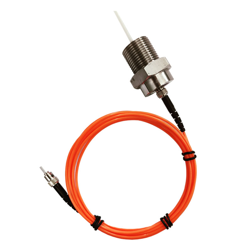
Fiber Optik Sıcaklık Probu Selection and Installation
Fiber optik sıcaklık probları for transformer applications are manufactured in several configurations. Winding-embedded probes are designed with a flat, thin profile that fits between conductor turns or along insulation spacers. Surface-mount probes with adhesive or mechanical fixation are used for core, tank wall, and bushing base measurement. Probes for oil temperature measurement are housed in stainless steel thermowells installed in standard tank fittings. During transformer manufacture, probes are installed at the factory and their fiber cables are routed through the winding structure and out of the tank through dedicated fiber optic feedthroughs — hermetically sealed fittings that maintain the transformer’s oil and gas integrity.
Fiber Optic Transmission Cable
The optical fiber cable connecting each probe to the demodulator is a single-strand or multi-strand glass fiber with protective buffer and jacket layers selected for compatibility with transformer oil inside the tank and for UV resistance, moisture protection, and mechanical durability outside the tank. Cable routing from the tank wall feedthrough to the demodulator in the substation relay room typically uses armored or conduit-protected fiber cable rated for outdoor substation environments.
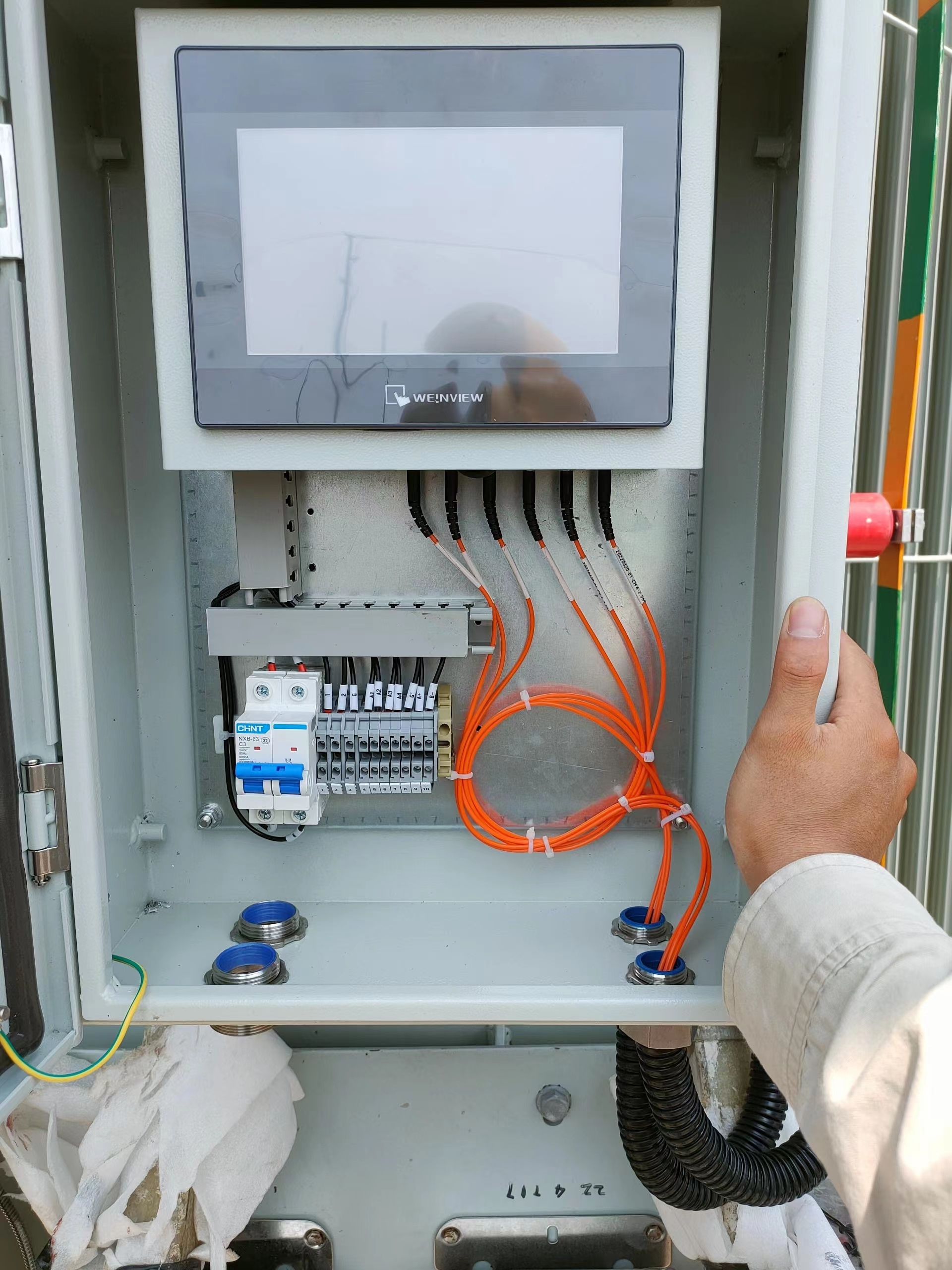
Fiber Optic Demodulator — Multi-Channel Signal Processing
The fiber optik demodülatör is the central instrumentation unit. It generates precisely timed excitation light pulses, captures the fluorescent return signal from each probe, digitally processes the decay waveform to extract temperature, and outputs calibrated readings on all channels simultaneously. Industrial-grade demodulators designed for substation environments support 4, 8, 16, or more measurement channels and are built to operate reliably across the wide ambient temperature range, nem seviyeleri, and electromagnetic conditions encountered in substation control rooms and marshalling kiosks.
Communication Interfaces and Substation Automation Integration
Modern demodulators provide multiple communication interfaces to support integration with substation automation systems. Standard outputs include analog 4–20 mA signals for legacy relay inputs, RS485 serial with Modbus RTU protocol, Ethernet with Modbus TCP or IEC 61850 MMS, and relay contact outputs for alarm and trip functions. IEC 61850 entegrasyon is particularly important for new digital substations, enabling the temperature monitoring system to publish data as GOOSE messages or as part of the substation’s logical node structure for direct consumption by protection IEDs, bölme kontrolörleri, and the station SCADA HMI.
Monitoring Software and Data Management Platform
Dedicated monitoring software provides real-time dashboards displaying all temperature channels, trend charts showing thermal history over hours, günler, and months, configurable alarm thresholds with escalation logic, and automated report generation for regulatory and asset management purposes. Advanced platforms incorporate thermal models compliant with IEC 60076-7 ve IEEE C57.91, allowing the software to compute remaining insulation life consumption, dynamic load capacity, and predicted time to hot-spot temperature limit based on current loading trajectory. Historical temperature data is archived and can be exported to utility enterprise asset management (EAM) sistemler, historian databases, ve bulut tabanlı analiz platformları.
9. Application Scenarios Across Transformer Types
High-Voltage Power Transformers (110 kV – 800 kV)
Large power transformers in transmission substations are the most critical and expensive single assets in the electrical grid. A single transformer can cost several million dollars and have a lead time of one to two years for replacement. Embedding floresan fiber optik sıcaklık sensörleri in the HV, AG, and tertiary windings during manufacture provides the most comprehensive thermal intelligence available. Utilities use this data for protection relay input, dynamic rating to manage peak load periods, and condition-based maintenance planning to extend asset life. For transformers rated 220 kV ve üzeri, direct fiber optic hot-spot measurement is increasingly specified as a standard requirement in procurement specifications.
Dağıtım Transformatörleri
While individual distribution transformers represent a lower capital investment, the sheer number of units in a utility’s fleet and the increasing loading from electric vehicle charging, heat pumps, and distributed generation create new thermal management challenges. Fiber optic monitoring of key distribution transformers at heavily loaded feeders provides data for load forecasting, network planning, and targeted reinforcement. Kompakt, cost-effective multi-channel demodulators make monitoring economically viable for this application tier.
Traction Transformers for Railway Electrification
Traction transformers in railway substations experience highly dynamic and cyclical loading profiles as trains accelerate, cruise, and regenerate. These load transients produce rapid winding temperature fluctuations that WTIs cannot track accurately. Fiber optik sıcaklık probları with fast response times capture these transients in real time, enabling precise thermal protection and supporting the dynamic rating needed to maximize train frequency on busy routes.
Rectifier Transformers and Electric Arc Furnace Transformers
Industrial transformers supplying DC rectifiers and electric arc furnaces operate under extreme conditions — high harmonic content, heavy overloads, ve sık sık yük döngüsü. Harmonic currents generate additional eddy current losses in the windings that elevate hot-spot temperature above values predicted by standard thermal models. Direct fiber optic hot-spot measurement provides the true thermal picture, protecting these transformers from premature insulation aging and enabling operators to optimize furnace duty cycles.
Offshore Wind and Renewable Energy Step-Up Transformers
Transformers installed on offshore wind turbine platforms or in onshore collector substations face unique challenges — remote location, limited access for maintenance, harsh marine environments, and variable generation profiles. Fiber optic transformer monitoring provides continuous thermal data without requiring site visits, supports remote diagnostics, and feeds into wind farm SCADA systems for centralized fleet management. The maintenance-free nature of fiber optic sensors is especially valuable in offshore installations where any intervention requires vessel mobilization and favorable weather windows.
Data Center and Critical-Load Supply Transformers
Data centers demand the highest levels of power reliability. Transformers supplying critical IT loads must operate within safe thermal limits at all times, including during N-1 contingency conditions when a parallel transformer is out of service and the remaining unit carries full load. Real-time fiber optic hot-spot monitoring gives data center operators the confidence to utilize transformer capacity fully during contingencies while maintaining documented thermal safety margins.
10. FAQs About Substation Transformer Temperature Monitoring
1. Çeyrek: What is advanced temperature monitoring for substation transformers?
Advanced temperature monitoring for substation transformers is the practice of using embedded floresan fiber optik sensörler to continuously measure actual winding hot-spot temperature, top-oil temperature, çekirdek sıcaklığı, bushing temperature, and tap changer temperature in real time. Unlike traditional instruments that estimate temperatures indirectly, advanced monitoring provides direct measurement data for thermal protection, dynamic loading, ve duruma dayalı bakım.
2. Çeyrek: Why are fiber optic sensors the best choice for transformer internal temperature measurement?
Fiber optik sıcaklık sensörleri are the only technology that can be safely embedded inside high-voltage transformer windings. They are completely non-metallic and non-conductive, so they do not create dielectric breakdown paths or interact with the transformer’s electromagnetic fields. They are immune to EMI, trafo yağıyla uyumlu, and maintain calibration accuracy for the full life of the transformer.
3. Çeyrek: How are fiber optic probes installed inside transformer windings?
Fiber optik sıcaklık probları are installed during the transformer manufacturing process. The thin, flat probe is placed between conductor turns or alongside insulation spacers at the predicted hot-spot location during the winding operation. The optical fiber cable is then routed through the winding structure, along the lead assembly, and out of the transformer tank through a hermetically sealed fiber optic feedthrough fitting in the tank wall.
4. Çeyrek: Can fiber optic sensors withstand transformer oil environments?
Evet. Fiber optic probes for transformer applications are encapsulated in materials specifically selected for long-term compatibility with mineral oil, natural ester, and synthetic ester insulating fluids. They have been proven in field service for over 25 years with no degradation of optical performance, mekanik bütünlük, or measurement accuracy due to oil exposure.
S5: What is the measurement accuracy of a fiber optic transformer monitoring system?
Endüstriyel floresan fiber optik sıcaklık sensörleri typically achieve an accuracy of ±0.5 °C to ±1 °C over their full operating range. This level of accuracy is maintained throughout the sensor’s life without recalibration — significantly better than the ±5 °C to ±15 °C estimation error typical of conventional winding temperature indicators.
S6: How many monitoring points can a single demodulator support?
Çok kanallı fiber optic demodulators designed for substation transformer applications are available in configurations supporting 4, 8, 16, 24, or more channels per unit. A typical large power transformer installation uses 6 ile 12 channels to cover HV winding hot spots, LV winding hot spots, üst yağ, alt yağ, çekirdek, and bushing or tap changer locations. Multiple demodulators can be networked for transformer banks or multi-transformer substations.
S7: How does the fiber optic monitoring system integrate with substation SCADA?
The fiber optik demodülatör provides communication via Modbus RTU (RS485), Modbus TCP'si (ethernet), IEC 61850 MMS/GOOSE, and analog 4–20 mA outputs. Temperature readings, alarm durumu, and diagnostic data are published to the substation SCADA system, koruma röleleri, and bay controllers through these standard interfaces. In IEC 61850 dijital trafo merkezleri, the demodulator can function as an IED publishing temperature logical nodes directly onto the station bus.
S8: What is the service life of fiber optic temperature sensors in a transformer?
Fiber optic sensors embedded in transformers have demonstrated field service lives exceeding 25 yıllar, matching or exceeding the design life of the host transformer. The sensors have no wearing parts, no electrical connections inside the tank, and no drift mechanisms. Once installed during manufacture, they require no maintenance or recalibration for the life of the transformer.
S9: Can fiber optic monitoring be retrofitted to existing in-service transformers?
Retrofitting fiber optic sensors inside the windings of an existing transformer requires de-tanking and partial disassembly, which is generally only practical during a major overhaul or repair. Fakat, fiber optic probes can be installed in existing thermowell fittings for oil temperature measurement, on accessible bushing bases, and on external surfaces without opening the transformer. Retrofit solutions provide significant monitoring improvements even without winding-embedded sensors.
S10: How does advanced temperature monitoring support dynamic transformer rating?
Dynamic transformer rating uses real-time hot-spot temperature data — rather than conservative nameplate assumptions — to calculate the transformer’s actual available loading capacity at any given moment. When the measured hot-spot temperature is below the rated limit due to favorable ambient conditions, low preceding load, or effective cooling, the monitoring system indicates that additional load can be safely applied. This capability allows utilities to defer capital expenditure on new transformer installations and maximize utilization of existing assets.
Sorumluluk reddi beyanı: Bu makalede verilen bilgiler yalnızca genel bilgilendirme ve eğitim amaçlıdır. Doğruluğu sağlamak için her türlü çaba gösterilmiş olsa da, Fjinno makes no warranties or representations regarding the completeness or applicability of the content to any specific transformer installation or operating condition. Ürün özellikleri, sıcaklık aralıkları, ölçüm doğruluğu, and system capabilities may vary depending on application requirements and site conditions. Transformer temperature monitoring system design should always be carried out in consultation with qualified engineers. For project-specific technical consultation and product selection, please contact the engineering team at www.fjinno.net. All product names, trademarks, and registered trademarks mentioned are the property of their respective owners.

Fiber optik sıcaklık sensörü, Akıllı izleme sistemi, Çin'de dağıtılmış fiber optik üreticisi
 |
 |
 |