 Vihisi joto vya INNO fiber optic ,mifumo ya ufuatiliaji wa joto.
Mambo muhimu ya kuchukua: Sensorer za Joto la Fiber Optic za Fluorescent
- Usahihi wa hali ya juu: ±1°C measurement precision across -40°C to +260°C range
- Usanifu wa Scalable: Transmita moja inasaidia 1-64 channels for comprehensive monitoring
- Majibu ya Haraka: <1 second reaction time for real-time temperature tracking
- Flexible Installation: 0-80 meter fiber optic cable length with customizable probe diameters
- Kinga kamili ya EMI: 100% dielectric design eliminates electromagnetic interference
- Point-Type Precision: Direct hotspot detection at critical transformer locations
- Maintenance-Free Operation: 10+ year service life with zero calibration requirements
- Ubinafsishaji kamili: Vipimo vya uchunguzi, urefu wa cable, housing type, and mounting hardware tailored to specifications
Jedwali la Yaliyomo
- Why Do Power Transformers Require Continuous Temperature Monitoring Systems?
- Ni Nini 5 Main Fiber Optic Temperature Sensing Technologies?
- What Components Make Up a Complete Fluorescent Monitoring System?
- How Does Fluorescent Fiber Optic Temperature Sensing Work?
- What Are the Key Technical Specifications?
- Why Does DTS Fall Short for Precision Monitoring?
- What Limitations Do FBG Sensors Have?
- Why Is GaAs Technology Not Optimal?
- When Do Sapphire Sensors Become Impractical?
- What Are the Differences Between Dry-Type and Oil-Immersed Monitoring?
- How Do These 5 Technologies Compare?
- What Customization Options Are Available?
- How Should Sensors Be Installed?
- What Results Have Users Achieved?
- Maswali Yanayoulizwa Mara Kwa Mara
1. Why Do Power Transformers Require Continuous Temperature Monitoring Systems?

Power transformers represent critical infrastructure assets, na thermal management directly impacting operational lifespan and grid reliability. Winding hotspots exceeding design temperatures accelerate insulation degradation, with every 6°C increase above rated limits halving insulation life expectancy according to IEEE C57.91 standards.
Traditional resistance temperature detectors (RTDs) and thermocouples face severe limitations in high-voltage environments. Metal-based sensors create electromagnetic interference pathways and require complex insulation schemes. Sensorer za joto za fiber optic eliminate these constraints through completely dielectric construction.
Critical Monitoring Points in Transformers
- Winding hotspots: High-current conductor locations experiencing maximum thermal stress
- Core temperatures: Magnetic core sections with elevated heat generation
- Oil circulation paths: Coolant flow monitoring in oil-immersed units
- Bushing interfaces: Connection points vulnerable to thermal degradation
- Tap changer assemblies: Mechanical switching components generating localized heat
2. Ni Nini 5 Main Fiber Optic Temperature Sensing Technologies Available for Ufuatiliaji wa Transformer?

Overview of Fiber Optic Temperature Measurement Technologies
The market offers five distinct fiber optic sensing technologies, each employing different physical principles for temperature measurement:
Sensorer za Fiber Optic za Fluorescent
Utilize rare-earth phosphor materials deposited on fiber tip. Temperature changes alter fluorescent decay time (lifetime-based measurement). Offers point-type sensing with exceptional accuracy.
Kihisi cha Halijoto Kilichosambazwa (DTS)
Employs Raman or Brillouin scattering along entire fiber length. Provides continuous temperature profile but with reduced spatial resolution and accuracy compared to point sensors.
Fiber Bragg Grating (FBG) Sensorer
Uses periodic refractive index variations inscribed in fiber core. Temperature shifts change Bragg wavelength reflection. Enables quasi-distributed measurement at discrete grating locations.
Gallium Arsenide (GaAs) Crystal Sensors
Relies on bandgap absorption edge shift in semiconductor crystal. Temperature modifies optical absorption spectrum measured through transmission analysis.
Sapphire Fiber Sensors
Employs single-crystal sapphire fiber with blackbody radiation measurement or embedded sensor elements. Designed for extreme high-temperature applications exceeding standard glass fiber limits.
3. What Components Make Up a Complete Fluorescent Fiber Optic Temperature Monitoring System?
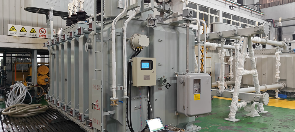
Kina transformer winding temperature monitoring system consists of integrated hardware and installation accessories:
Vipengele vya Mfumo wa Msingi
IF-TF Series Transformer Fiber Optic Temperature Measurement Device
The central processing unit combines optical interrogation, usindikaji wa ishara, na violesura vya mawasiliano. Mtu mmoja kisambaza joto Hushughulikia 1-64 independent channels with individual channel configuration.
Internal Fiber Optic Sensing Probes
Fluorescent-tipped sensors designed for direct winding installation. Probe diameter customization accommodates various conductor geometries, typically ranging 1.0-3.0mm for transformer applications.
External Fiber Optic Sensing Probes
Surface-mount or ambient temperature sensors for tank wall, cooling system, na ufuatiliaji wa mazingira. Different housing configurations protect against oil immersion, outdoor weather, and mechanical stress.
Installation Hardware
Feedthrough/Flange Assemblies
Sealed penetration components maintaining transformer tank integrity while routing nyaya za fiber optic from internal sensors to external interrogator. Custom flange dimensions match existing transformer penetrations.
Control Enclosures
Weather-resistant cabinets housing temperature transmitters, power supplies, and communication modules. Available in wall-mount or free-standing configurations.
Protection Boxes
- Integrated Protection Box: Single-piece enclosure for compact installations
- Split Protection Box: Modular design separating sensor interfaces from processing electronics
- Protective Covers: Additional shielding for split-type configurations in harsh environments
Mounting Hardware
Specialized brackets, clamps, and fixing components securing sensors to windings, cores, and structural elements without compromising electrical clearances.
4. Jinsi gani Kuhisi Halijoto ya Fiber Optic ya Fluorescent Work in Transformer Applications?
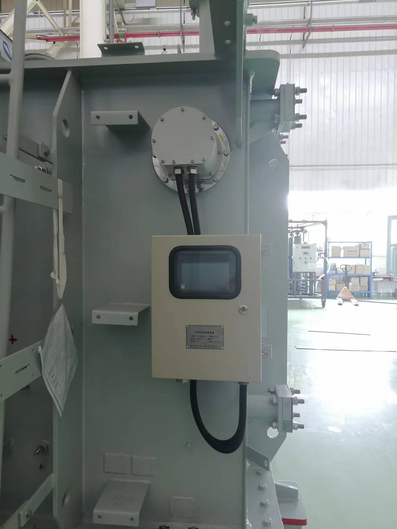
Upimaji wa joto la nyuzi za transfoma
Fluorescent temperature measurement operates through time-domain optical analysis of rare-earth phosphor materials:
Mchakato wa Kipimo
- Optical Excitation: Pulsed LED light (typically 405-450nm wavelength) travels through fiber to phosphor-coated probe tip
- Fluorescent Response: Absorbed photons excite phosphor electrons to higher energy states
- Decay Emission: Returning electrons emit longer-wavelength fluorescent light (500-700nm range)
- Lifetime Measurement: Detector analyzes exponential decay time of fluorescent emission
- Temperature Calculation: Decay lifetime correlates directly to absolute temperature through calibrated algorithms
Faida katika Mazingira ya Juu-Voltage
Unlike wavelength-shift technologies affected by fiber bending or connector loss, lifetime-based measurement remains immune to optical power variations. This intrinsic self-referencing eliminates calibration drift and signal degradation issues.
The dielectric fiber optic sensor introduces zero capacitance or conductivity into transformer windings. Complete EMI immunity prevents measurement errors from switching transients, shughuli ya kutokwa kwa sehemu, or adjacent high-current conductors.
5. Je, ni Vipimo Muhimu vya Kiufundi vya Sensorer za Joto la Fiber Optic za Fluorescent?
Performance Parameters
| Vipimo | Standard Range | Custom Options |
|---|---|---|
| Kiwango cha Joto | -40°C hadi +260°C | Extended ranges available for specialized applications |
| Usahihi wa Kipimo | ±1°C (±0.5°C optional) | Enhanced calibration for tighter tolerances |
| Muda wa Majibu | <1 pili | Probe diameter affects thermal mass |
| Azimio | 0.1°C | System display and data logging precision |
| Fiber Cable Length | 0-80 meters standard | Extended lengths up to 200m with signal compensation |
| Uwezo wa Kituo | 1-64 njia kwa kila transmita | Expandable through multiple networked units |
| Kipenyo cha Uchunguzi | 1.0-3.0mm typical | Custom dimensions for specific installation constraints |
System Architecture Flexibility
Modular multi-channel temperature monitoring configurations scale from single-point critical monitoring to comprehensive 64-channel networks covering all transformer thermal zones. Each channel operates independently with programmable alarm thresholds and individual calibration coefficients.
6. Why Does Distributed Temperature Sensing (DTS) Fall Short for Precision Transformer Monitoring?
Wakati Mifumo ya DTS provide continuous temperature profiles along fiber length, fundamental physical constraints limit transformer applicability:
Spatial Resolution Limitations
Commercial Raman-based DTS achieves 0.5-1.0 meter spatial resolution at best. Transformer winding hotspots occupy centimeter-scale regions, making pinpoint detection impossible. Critical 10-20cm conductor sections between cooling ducts cannot be individually resolved.
Accuracy Constraints
DTS typical accuracy of ±2-5°C falls short of transformer thermal management requirements. IEEE standards recommend ±1°C or better for meaningful insulation life calculations. The statistical averaging inherent in backscatter analysis prevents achieving point-sensor precision.
Utata wa Ufungaji
Distributed sensing requires continuous fiber routing through monitored regions. Transformer windings present tortuous paths with tight bending radii incompatible with standard single-mode fiber (>30mm bend radius limits). Specialized bend-insensitive fiber adds significant cost.
Cost Structure
DTS interrogators carry $15,000-50,000 price tags regardless of monitored length. For transformers requiring 8-12 critical point measurements, per-channel cost vastly exceeds point-sensor alternatives. Economic justification demands 100+ meter cable runs inappropriate for compact transformer geometries.
7. What Limitations Do Fiber Bragg Grating (FBG) Sensors Have in Transformer Environments?
Strain-Temperature Cross-Sensitivity
Sensorer za FBG respond equally to temperature and mechanical strain. Transformer windings experience electromagnetic forces during fault conditions and thermal expansion cycles. Distinguishing temperature changes from strain-induced wavelength shifts requires complex compensation schemes or dual-grating configurations doubling sensor count.
Wavelength Multiplexing Limits
Practical FBG networks accommodate 8-16 sensors per fiber using wavelength-division multiplexing. Large transformers requiring 32-64 monitoring points need multiple fiber runs and interrogators. This contrasts with fluorescent systems serving 64 channels through time-division multiplexing on single fiber pairs.
Electromagnetic Field Sensitivity
While fiber itself remains non-conductive, FBG wavelength stability depends on precise refractive index periodicity. Strong electromagnetic fields induce minor fiber stress through magnetostriction in trace dopants. High-accuracy applications require EM-isolated fiber routing impractical within winding structures.
Interrogator Complexity
Tunable laser sources or spectrometer-based Wadadisi wa FBG gharama $8,000-25,000 kwa kila kitengo. Multi-channel configurations need expensive wavelength referencing to maintain ±0.5°C accuracy. Fluorescent interrogation uses simple LED sources and photomultiplier detection at fraction of cost.
8. Why Is Gallium Arsenide (GaAs) Technology Not Optimal for Transformer Temperature Monitoring?
Limited Temperature Range
Sensorer za GaAs typically operate -40°C to +150°C, inadequate for transformer hotspot monitoring requiring 200°C+ capability. Winding temperatures during overload conditions or cooling system failures regularly exceed GaAs upper limits.
Transmission Loss Sensitivity
GaAs measurement relies on optical power transmission through crystal, making performance highly dependent on connector quality and fiber cleanliness. Oil contamination on connectors creates measurement errors absent in fluorescent lifetime-based systems immune to power variations.
Calibration Stability Issues
Bandgap characteristics of GaAs crystals drift with long-term radiation exposure and thermal cycling. Transformer environments with partial discharge UV emissions accelerate aging. Annual recalibration requirements contradict maintenance-free operational goals.
Point Count Economics
Kila moja GaAs temperature probe requires dedicated fiber pair to interrogator. A 32-channel system needs 64 fiber connections versus single fiber pair serving 64 sensorer za fluorescent. Installation labor and component costs scale linearly with channel count.
9. When Do Sapphire Fiber Optic Sensors Become Impractical for Standard Transformer Applications?
Extreme Temperature Specification
Sapphire fiber sensors excel at 800-1800°C monitoring in molten metal, furnace, and combustion applications. Transformer operating temperatures (-40°C to +180°C typical, +200°C emergency) fall far below sapphire justification threshold. Using 1000°C-rated sensors for 150°C applications wastes cost premium.
Mechanical Fragility
Single-crystal sapphire fibers exhibit brittleness exceeding silica glass. Winding installation involves routing through narrow spaces, around sharp corners, and past vibrating components. Sapphire’s limited flexibility (minimum bend radius 50-100mm) prevents installation in compact transformer geometries requiring 10-20mm radii.
Connection Complexity
Sapphire-to-silica fiber splicing requires precision alignment and specialized fusion techniques. Each probe connection adds failure points and 1-3dB optical loss. Sensorer za fluorescent use standard telecom-grade connectors with field-replaceable cables.
Cost Barrier
Sapphire fiber sensors cost 5-10× standard fluorescent probes. A 16-channel transformer monitoring system shows $25,000-40,000 sensor cost premium with zero performance benefit in <200°C operating range. Return on investment never materializes for standard power equipment.
10. What Are the Critical Differences Between Dry-Type and Oil-Immersed Transformer Temperature Monitoring Requirements?
Dry-Type Transformer Monitoring
Direct Winding Access
Transfoma za aina kavu allow straightforward sensor installation during manufacturing or retrofits. Probes embed directly into winding structures or attach to conductor surfaces without sealing concerns.
Air Cooling Dynamics
Natural or forced air cooling creates temperature stratification. Monitoring requires multiple vertical positions capturing bottom-to-top thermal gradients. Typical 20-35kV dry-type units employ 8-12 pointi za kipimo cha joto across winding height and phase windings.
Enclosure Considerations
Indoor installations allow ambient interrogator mounting. External protection boxes resist dust and humidity but avoid oil-tight sealing requirements. Standard IP54-rated enclosures suffice for most environments.
Oil-Immersed Transformer Monitoring
Hermetic Feedthrough Requirements
Transfoma ya kuzama kwa mafuta demand oil-tight fiber penetrations maintaining tank integrity. Desturi flange assemblies integrate with existing bushing turrets or require dedicated tank nozzles. Mtihani wa shinikizo kwa 0.3-0.5 bar validates seal quality.
Oil Contamination Resistance
Sensors endure continuous mineral oil immersion at elevated temperatures. Probe materials must resist oil degradation, maintain dielectric strength, and avoid leaching contaminants affecting oil chemistry. Fluorescent phosphor coatings demonstrate 20+ year stability in transformer oil.
Winding Immersion Access
Installation occurs during factory assembly or major overhauls requiring oil drainage. Sensors route through pressboard insulation structures, requiring pre-planned cable paths. Retrofits face significant labor costs versus dry-type accessibility.
Top-Oil vs. Winding Temperature
Oil-immersed units need both direct winding hotspot sensors and top-oil temperature measurement. Thermal models calculating hotspot-to-top-oil gradients validate against direct measurements, improving load management accuracy.
11. How Do These 5 Technologies Compare for Critical Transformer Monitoring Parameters?
| Kigezo | Fluorescent | DTS | FBG | GaAs | Sapphire |
|---|---|---|---|---|---|
| Aina ya Kipimo | Uhakika | Imesambazwa | Quasi-distributed | Uhakika | Uhakika |
| Usahihi | ±1°C | ±2-5°C | ±1-2°C | ±2°C | ±2-3°C |
| Kiwango cha Joto | -40 hadi +260°C | -40 hadi +150°C | -40 hadi +300°C | -40 hadi +150°C | +200 to +1800°C |
| Muda wa Majibu | <1 pili | 5-30 sekunde | 1-3 sekunde | 2-5 sekunde | 3-8 sekunde |
| Channels per Fiber | 64 | Kuendelea | 8-16 | 1 | 1 |
| Kinga ya EMI | Kamilisha | Kamilisha | Juu | Kamilisha | Kamilisha |
| Strain Sensitivity | Hakuna | Minimal | Juu | Chini | Minimal |
| Calibration Stability | 10+ miaka | Annual | 2-3 miaka | 1-2 miaka | 3-5 miaka |
| Kubadilika kwa Ufungaji | Bora kabisa | Kikomo | Nzuri | Bora kabisa | Maskini |
| Bend Radius | 10-15mm | 30-50mm | 20-30mm | 15-20mm | 50-100mm |
| Gharama ya Mfumo (16ch) | $12,000-18,000 | $30,000-55,000 | $18,000-28,000 | $15,000-22,000 | $35,000-60,000 |
| Transformer Suitability | Bora kabisa | Maskini | Wastani | Kikomo | Inappropriate |
Why Fluorescent Technology Dominates Transformer Applications
The comparison reveals sensorer za optic za nyuzi za fluorescent uniquely combine transformer-specific advantages:
- Precision hotspot detection: ±1°C accuracy at exact winding locations versus averaged distributed measurements
- Scalable architecture: 64 channels per transmitter reduces per-point cost below all alternatives
- Installation practicality: Small bend radius and flexible cable routing suit compact winding geometries
- Uendeshaji usio na matengenezo: 10-year calibration stability eliminates ongoing service costs
- Temperature range coverage: -40 to +260°C spans all normal and emergency transformer operating conditions
12. What Customization Options Are Available for Fluorescent Temperature Monitoring Systems?
Sensor Probe Customization
Diameter Options
Kawaida vipenyo vya uchunguzi range 1.0-3.0mm, with custom sizes available 0.5-5.0mm. Smaller diameters (0.5-1.5mm) suit tight winding spaces and minimize thermal impact on monitored conductors. Larger probes (3.0-5.0mm) provide mechanical robustness for surface-mount applications.
Cable Length Configuration
Factory-terminated cables come in 5-80 meter standard lengths. Custom lengths accommodate specific tank dimensions and control room distances. Extended runs to 200 meters require signal amplification but maintain measurement accuracy.
Housing Materials
- Stainless steel: General-purpose transformer oil immersion
- Teflon-coated: Enhanced chemical resistance for synthetic fluids
- Ceramic tips: Maximum temperature capability and abrasion resistance
- Flexible silicone: Vibration-prone locations and tight routing paths
System Architecture Options
Channel Count Selection
Temperature transmitters offer modular channel configurations: 4, 8, 16, 32, or 64-channel models. Right-sizing prevents over-investment while maintaining expansion capability. Unused channels remain available for system upgrades without equipment replacement.
Violesura vya Mawasiliano
- Modbus RTU/TCP: Standard SCADA integration protocol
- IEC 61850: Substation automation compatibility
- Profibus/Profinet: Industrial automation environments
- 4-20mA analog: Legacy control system interfacing
- Ethaneti/IP: Modern networked architectures
Enclosure Customization
Protection Class
Enclosures specified to IP54, IP65, or IP66 ratings based on installation environment. Outdoor substations require IP65/66 weather resistance while indoor installations use IP54 dust protection.
Integrated vs. Split Configuration
Integrated protection boxes combine all components in single enclosure for simple installations. Split configurations separate sensor junction boxes (imewekwa kwenye transformer) from interrogator cabinets (located in control rooms), reducing electromagnetic exposure to electronics.
Hazardous Area Certification
Explosion-proof enclosures meet ATEX, IECEx, or NEC Class I Division 2 requirements for installations near oil-filled equipment or flammable gas locations.
Mounting Hardware Adaptation
Desturi flange assemblies match existing transformer penetrations (DN25-DN100 standard pipe sizes). Retrofit kits adapt to various bushing turret configurations without modifying pressurized tank structures. Clamp designs accommodate conductor diameters from 10-150mm for direct winding attachment.
13. How Should Fluorescent Fiber Optic Sensors Be Installed in Different Types of Transformers?
Pre-Installation Planning
Thermal Mapping Analysis
Identify critical monitoring locations through design review and thermal modeling. Typical ufuatiliaji wa joto la transformer prioritizes:
- Top winding sections experiencing highest oil temperatures
- Current-carrying conductor centers with maximum I²R losses
- Core leg surfaces adjacent to winding assemblies
- Oil pump inlet/outlet for circulation verification
Dry-Type Transformer Installation
During Manufacturing
- Winding integration: Route nyaya za fiber optic alongside conductor layers during winding process
- Probe positioning: Place sensor tips at predetermined hotspot locations with 50-100mm clearance to adjacent conductors
- Strain relief: Secure cables to winding structure at 200-300mm intervals preventing vibration fatigue
- Exit routing: Bring all fiber cables to designated terminal blocks on transformer frame
Retrofit Procedures
- Kupunguza nishati: Verify zero voltage and discharge residual capacitance
- Access preparation: Remove necessary covers exposing target winding sections
- Sensor insertion: Thread probes into winding spaces using guide wires if necessary
- Adhesive bonding: Use high-temperature epoxy or silicone securing probes to conductor surfaces
- Cable management: Route fibers avoiding sharp edges and maintaining minimum bend radius
Oil-Immersed Transformer Installation
Ufungaji wa Kiwanda
- Winding preparation: Install sensors during active part assembly before tank enclosure
- Insulation integration: Route fibers through pressboard barriers using pre-drilled passages
- Flange mounting: Weld or bolt fiber optic feedthrough flanges to tank wall at designated locations
- Internal routing: Bring sensor cables from winding to flange penetration with adequate slack for thermal expansion
- Sealing verification: Pressure test tank to 0.5 bar confirming no oil leakage at penetrations
Field Retrofit Installation
- Outage coordination: Schedule installation during planned maintenance requiring oil drainage
- Oil removal: Drain transformer oil to appropriate level exposing winding assembly
- Tank modification: Machine and weld new flange nozzles if existing penetrations unavailable
- Sensor deployment: Lower probes into tank using extension rods, securing to windings via pre-installed attachment points
- Connection completion: Terminate fiber cables at external junction boxes, connect to kisambaza joto
- System testing: Verify all channels reading correctly before oil refilling
- Recommissioning: Refill oil, vacuum process, and perform acceptance testing
Installation Best Practices
- Minimum bend radius: Maintain 15mm radius for standard fiber optic cable throughout routing
- Connector protection: Use dust caps on all unused connections preventing contamination
- Labeling: Mark each fiber cable with channel number and monitoring location for maintenance reference
- Nyaraka: Photograph sensor locations and record exact coordinates in transformer drawings
- Testing protocol: Verify each channel measurement against RTD reference before commissioning
14. What Results Have Users Achieved with Fluorescent Fiber Optic Temperature Monitoring in Transformers?
230kV Substation Transformer Overload Prevention
A utility operating 230kV/34.5kV, 150MVA transformers installed 16-channel fluorescent temperature monitoring detecting winding hotspots 15-25°C above top-oil readings. The system identified cooling system degradation three weeks before traditional indicators, preventing thermal runaway during peak load period. Avoided $2.8M transformer replacement and 6-week outage.
Industrial 13.8kV Dry-Type Transformer Load Optimization
Manufacturing facility with four 5MVA dry-type transformers implemented 12-point monitoring per unit. Wakati halisi hotspot temperature data enabled dynamic load balancing, increasing total plant capacity 18% without equipment addition. Precise thermal tracking allowed confident operation at 115% nameplate rating during production peaks, previously limited to 95% by conservative estimates.
Offshore Platform Generator Step-Up Transformer
Oil platform 13.8kV/66kV transformers face space constraints preventing traditional cooling upgrades. Sensorer za optic za nyuzi provided accurate thermal data supporting revised loading calculations. Engineers confirmed 12% additional continuous rating based on actual hotspot measurements versus design assumptions, generating $340,000 annual revenue increase through enhanced generation capacity.
University Campus Substation Predictive Maintenance
Educational institution monitoring six campus transformers (10-25MVA) detected gradual cooling fan degradation through trending analysis. One unit showed 0.8°C/month hotspot temperature increase over 14 months despite stable load. Scheduled maintenance replaced failed fan motor before emergency failure, maintaining continuous campus operations during exam period.
Renewable Energy Collector Substation
Wind farm collector transformers experience highly variable loading from intermittent generation. Traditional thermal models assume steady-state conditions, poorly predicting dynamic thermal response. Ufuatiliaji wa joto wa njia nyingi revealed actual thermal time constants 40% faster than modeled values, enabling revised short-time overload ratings. Transmission constraint periods decreased 25%, improving project economics.
15. Frequently Asked Questions About Fluorescent Fiber Optic Temperature Sensors for Transformers

Can fluorescent sensors operate in SF6 gas-insulated transformers?
Ndiyo, probes ya optic ya nyuzi za fluorescent function identically in SF6, air, vacuum, or liquid insulation. The sensing mechanism depends only on phosphor temperature, not surrounding medium. SF6 installations use same sensors as oil-immersed units with appropriate sealing for gas containment.
How do I retrofit sensors into energized transformers?
Energized installation is not recommended for safety and technical reasons. Sensor ya joto ya transfoma installation requires de-energization, oil drainage (for oil-immersed types), and physical access to windings. Plan retrofits during scheduled maintenance outages.
What happens if a fiber cable breaks?
Channel monitoring that fiber route fails, but other channels continue normal operation. System alerts indicate fiber break through loss-of-signal alarm. Redundant fiber routing or spare channels mitigate single-point failures for critical applications.
Do sensors require periodic calibration?
No field calibration needed for 10+ miaka. Fluorescent temperature measurement stability derives from intrinsic material properties unchanged by environmental exposure. Factory calibration certificates document accuracy, with optional re-certification during major transformer overhauls.
Can I expand channel count after initial installation?
Ndiyo, if original kisambaza joto has unused channel capacity. Add sensors and connect to vacant channels without system reprogramming. Systems at full capacity require additional transmitter modules communicating through same network.
What communication distance limits exist between sensors and transmitter?
Standard systems support 80-meter fiber runs between probes and transmitter. Extended configurations reach 200 meters using signal amplification. Optical power budget calculations determine maximum distance for specific channel counts and fiber types.
How do fluorescent sensors perform in partial discharge environments?
Completely unaffected. Unlike electrical sensors detecting PD as noise, optical systems ignore electromagnetic interference. UV radiation from PD activity does not degrade phosphor materials over typical transformer lifespans.
Can I use one transmitter for multiple transformers?
Ndiyo, if total channel count stays within transmitter capacity and fiber routing is practical. A 64-channel unit can monitor four transformers with 16 pointi kila mmoja. Consider communication complexity and single-point failure risk when centralizing systems.
What maintenance do fluorescent systems require?
Essentially none. Check communication links and power supplies during routine substation inspections. Clean optical connectors if contamination suspected (rare in sealed installations). No sensor replacement, urekebishaji upya, or consumable parts for 10-20 maisha ya huduma ya mwaka.
How quickly can I obtain custom sensor configurations?
Standard customization (kipenyo cha uchunguzi, urefu wa cable, housing type) ships in 2-4 wiki. Complex requirements like specialized materials or certifications need 6-10 weeks engineering and manufacturing time. Discuss project timelines early for delivery planning.
Where Can You Source Professional Fluorescent Fiber Optic Temperature Monitoring Systems?
This website specializes in transformer fiber optic temperature sensors and complete monitoring systems. Our product range includes:
- IF-TF Series Fluorescent Temperature Transmitters: 1-64 channel configurations
- Custom Sensing Probes: Specifications tailored to your transformer design
- Complete Installation Kits: Feedthrough flanges, protection boxes, vifaa vya kuweka
- Msaada wa Kiufundi: Application engineering assistance and installation guidance
Why Choose Our Fluorescent Temperature Monitoring Solutions?
- ✓ 15+ years manufacturing experience in fiber optic sensing technology
- ✓ ISO 9001 certified production with rigorous quality control
- ✓ Full customization capabilities for probe dimensions and system architecture
- ✓ Competitive factory-direct pricing for OEM and wholesale orders
- ✓ Global technical support and application engineering services
- ✓ Proven reliability with 1000+ transformer installations worldwide
Contact our technical sales team kwa maelezo ya kina, pricing quotations, and project consultation. We provide customized solutions matching your exact transformer monitoring requirements.
Technical Disclaimers and Application Considerations
Information Accuracy: Technical specifications and performance data presented represent typical values based on standard configurations. Actual system performance depends on specific application conditions, installation quality, na mambo ya mazingira. Consult factory engineers for project-specific validation.
Application Responsibility: Users bear responsibility for proper sensor selection, taratibu za ufungaji, na ujumuishaji wa mfumo. Transformer temperature monitoring system design should follow IEEE C57.91, IEC 60076-7, and applicable local standards. Professional engineering review recommended for safety-critical applications.
Vipimo vya Bidhaa: Manufacturer reserves right to modify product specifications, vipengele, and pricing without prior notice as technology advances. Confirm current specifications before placing orders. Custom configurations may have different parameters than standard products described.
Mahitaji ya Ufungaji: Fiber optic sensor installation in energized equipment requires qualified electrical personnel following lockout/tagout procedures and utility safety protocols. Improper installation may damage transformers or create safety hazards. Manufacturer assumes no liability for installation errors or consequential damages.
Uchambuzi Linganishi: Technology comparisons reflect general industry characteristics and may not represent all manufacturers’ utekelezaji. Performance varies by supplier, mfano, and configuration. Independent verification recommended for critical procurement decisions.
No Warranty for Specific Use: While fluorescent fiber optic sensors suit most transformer applications, fitness for particular purpose requires engineering analysis. Unusual operating conditions, mazingira uliokithiri, or specialized requirements may need modified solutions. Consult technical support before finalizing designs.
Third-Party Products: References to specific technologies (DTS, FBG, GaAs, Sapphire) describe general technical approaches, not particular manufacturers’ bidhaa. Performance characteristics represent industry-typical ranges rather than specific product endorsements or criticisms.
Pricing Information: Cost estimates provided for comparison purposes only. Actual pricing depends on configuration, order quantity, mahitaji ya ubinafsishaji, and current market conditions. Request formal quotations for budget planning.

Sensor ya joto ya fiber optic, Mfumo wa ufuatiliaji wa akili, Kusambazwa fiber optic mtengenezaji nchini China
 |
|
 |