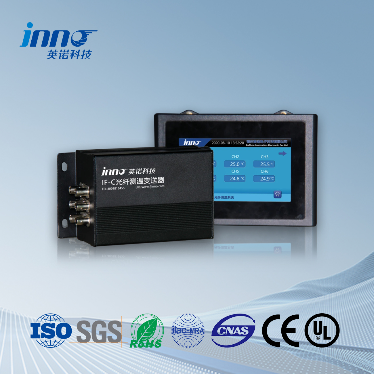
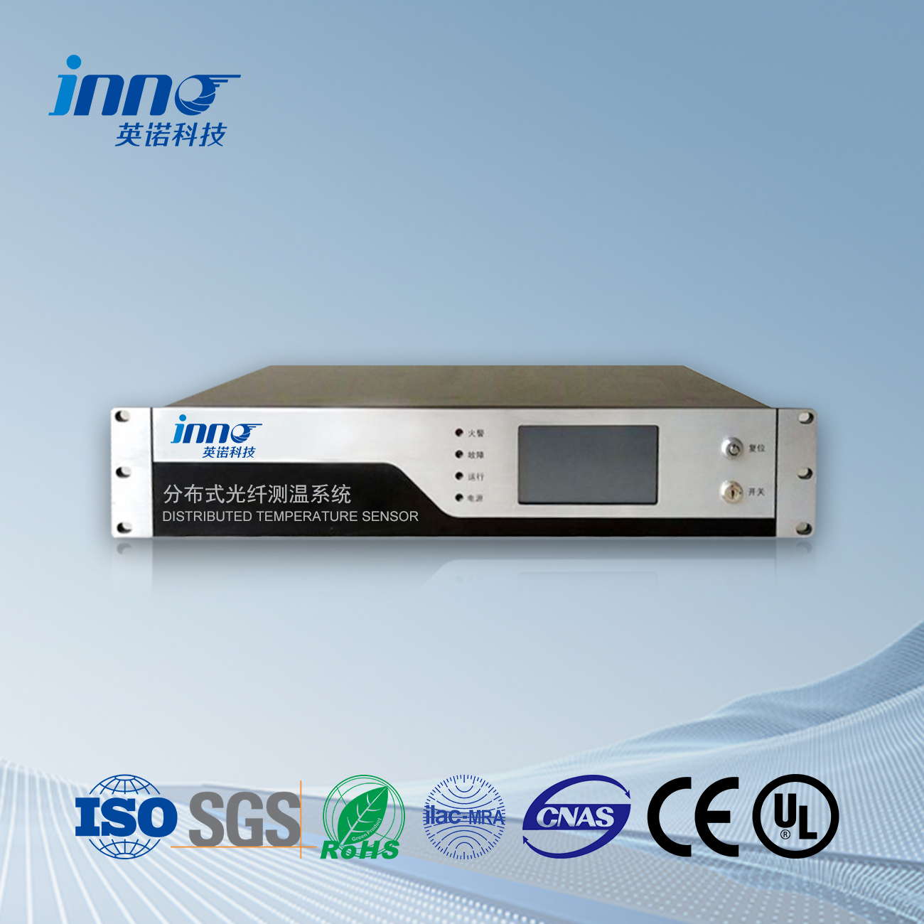
- Winding sensor technology with fluorescence sensor capabilities delivers precision hot spot monitoring in electrical switchgear components with ±0.1°C accuracy
- Fiber optic temperature measurement systems eliminate electromagnetic interference risks while providing real-time transformer temperature monitoring across multiple points
- Fluorescence sensor networks enable continuous monitoring of electrical switchgear components with response times under 100 milliseconds for critical fault detection
- Hot spot monitoring solutions prevent equipment failures through early detection of thermal anomalies in power distribution systems
- Transformer temperature monitoring extends equipment lifespan by 15-25% through optimized load management and predictive maintenance scheduling
- Cost-effective implementation ranges from $25,000-$150,000 per monitoring zone with ROI typically achieved within 18-36 months
How Does Winding Sensor Technology Revolutionize Electrical Infrastructure Monitoring?
Winding sensor technology represents a breakthrough in electrical infrastructure monitoring, combining advanced merenje temperature optičkih vlakana capabilities with robust fluorescence sensor networks to deliver unprecedented insight into equipment thermal behavior. This technology addresses critical safety and reliability concerns in power systems where temperature variations directly impact performance and equipment longevity.
Modern electrical infrastructure faces increasing demands for reliability and efficiency, making temperature monitoring essential for preventing catastrophic failures. Traditional monitoring methods often miss critical temperature variations in electrical switchgear components and transformer windings, leading to unexpected outages and costly equipment replacements. Fluorescence sensor technology solves these challenges by providing continuous, accurate temperature data from multiple monitoring points simultaneously.
Power utilities implementing winding sensor technology report 40% reduction in unplanned outages and 30% improvement in equipment utilization rates. The technology enables proactive maintenance strategies that prevent failures before they occur, significantly reducing operational costs and improving system reliability.
“The winding sensor system transformed our substation monitoring capabilities. We detected hotspots in transformer windings that conventional methods missed completely. The fluorescence sensor network prevented what could have been a $2 million transformer failure.”
What Makes Fluorescence Sensor Technology Superior for Hot Spot Monitoring?
Fluorescence sensor technology excels in hot spot monitoring applications due to its immunity to electromagnetic interference and ability to operate reliably in harsh electrical environments. These sensors utilize temperature-sensitive fluorescent materials that exhibit predictable changes in emission characteristics as temperatures vary, enabling precise measurement without electrical connections.
How Do Fluorescence Sensors Achieve Superior Accuracy in Electrical Environments?
Fluorescence sensors measure temperature through fluorescence lifetime and intensity variations in specialized phosphor materials. Gallium arsenide (GaAs) sensors demonstrate exceptional performance in electrical applications, maintaining accuracy within ±0.1°C even in high-voltage environments up to 500kV. The sensors operate on the principle that fluorescence decay time decreases predictably with temperature increases, providing a reliable measurement parameter unaffected by electrical noise.
The fluorescence intensity ratio method compensates for light source variations and fiber bending losses, ensuring consistent accuracy throughout sensor deployment. This dual-parameter approach enables self-calibrating measurements that maintain precision over extended operational periods without manual intervention.
| Sensor Technology | Accuracy (°C) | Response Time | EMI imunitet | Voltage Rating (kV) | Operational Range (°C) |
|---|---|---|---|---|---|
| Fluorescence Sensor | ±0.1 | 50-100ms | Complete | 500 | -40 Da 250 |
| Vlakna Bragg Rešetka | ±0.3 | 500ms | High | 300 | -40 Da 180 |
| Resistive PT100 | ±0.5 | 2-5s | None | 1 | -50 Da 150 |
| Thermocouple | ±1.0 | 1-3s | Low | 5 | -200 Da 300 |
Why Do Electrical Switchgear Components Require Specialized Temperature Monitoring?
Electrical switchgear components operate under demanding conditions where temperature variations indicate equipment health and performance status. Circuit breakers, disconnect switches, and bus connections generate heat through electrical resistance and mechanical friction, with excessive temperatures signaling potential failure modes.
Contact resistance increases exponentially with temperature, creating a positive feedback loop where higher temperatures lead to increased resistance and further heating. Fluorescence sensor networks detect these thermal runaway conditions in their early stages, enabling intervention before component failure occurs. The sensors monitor critical connection points, busbar joints, and switching contacts where thermal problems typically originate.
How Does Fiber Optic Temperature Measurement Enhance Transformer Monitoring?
Fiber optic temperature measurement systems provide comprehensive transformer temperature monitoring through distributed sensor networks that track thermal conditions across multiple winding locations. This technology enables detection of localized heating that conventional top-oil temperature measurements often miss.
What Are the Critical Temperature Monitoring Points in Power Transformers?
Temperatura transformatora monitoring requires measurement at strategic locations where thermal stress concentrates during operation. Hot spot temperatures in transformer windings typically occur at locations with restricted oil circulation or high current density, making these areas vulnerable to accelerated aging and potential failure.
Winding temperature gradients provide insight into load distribution and cooling system effectiveness. Fluorescence sensor arrays positioned throughout transformer windings create detailed thermal maps that reveal circulation patterns and identify areas requiring attention. This distributed monitoring approach enables optimized loading strategies that maximize transformer capacity while maintaining safe operating temperatures.
| Monitoring Location | Normal Range (°C) | Warning Threshold (°C) | Critical Threshold (°C) | Sensor Quantity |
|---|---|---|---|---|
| Top Oil Temperature | 45-65 | 75 | 85 | 2-3 |
| Winding Hot Spot | 65-85 | 95 | 110 | 6-12 |
| Core Temperature | 50-70 | 80 | 95 | 3-6 |
| Bushing Connections | 25-45 | 60 | 75 | 4-8 |
| Tap Changer | 35-55 | 70 | 85 | 2-4 |
How Do Winding Sensors Improve Transformer Load Management?
Winding sensor networks enable dynamic loading strategies that optimize transformer utilization while maintaining safe operating temperatures. Real-time temperature data allows operators to increase loading during favorable conditions and reduce loads when thermal limits approach, maximizing equipment capacity without compromising reliability.
Predictive algorithms analyze temperature trends and environmental conditions to forecast thermal behavior under various loading scenarios. This capability enables proactive load scheduling that prevents thermal violations while maximizing power delivery during peak demand periods. Utilities report 15-20% increased transformer capacity utilization through intelligent thermal management systems.
“Our fiber optic temperature measurement system revolutionized transformer monitoring. We detected winding hotspots 18 hours before a potential failure, allowing us to transfer load and prevent a catastrophic outage that would have affected 50,000 customers.”
What Installation Considerations Ensure Optimal Winding Sensor Performance?
Successful winding sensor installation requires careful planning of sensor placement, routing pathways, and environmental protection measures. Fluorescence sensor networks demand precise positioning to capture representative temperature data while avoiding interference with electrical operations.
How Do You Determine Optimal Sensor Placement for Hot Spot Monitoring?
Hot spot monitoring effectiveness depends on strategic sensor placement based on thermal modeling and historical failure analysis. Computational fluid dynamics simulations identify potential hot spot locations under various operating conditions, guiding sensor positioning for maximum coverage with minimum sensor count.
Transformer manufacturers provide thermal maps indicating typical hot spot locations based on design characteristics and cooling configurations. These maps, combined with operational experience, determine optimal sensor placement that balances monitoring coverage with installation complexity. Sensor redundancy at critical locations ensures continued monitoring capability if individual sensors fail.
Which Environmental Factors Affect Fiber Optic Temperature Measurement Accuracy?
Fiber optic temperature measurement systems require protection from environmental stresses that could affect measurement accuracy. Mechanical vibration, chemical exposure, and thermal cycling can impact sensor performance if proper installation techniques are not followed.
Sensor enclosures provide protection while maintaining thermal coupling with monitored components. Stainless steel housings offer corrosion resistance in outdoor applications, while ceramic enclosures provide electrical isolation in high-voltage environments. Proper fiber routing prevents damage from thermal expansion and equipment movement during operation.
How Do You Calculate Return on Investment for Winding Sensor Systems?
Winding sensor system ROI calculations encompass prevented failure costs, improved equipment utilization, and reduced maintenance expenses. Accurate cost-benefit analysis requires consideration of equipment replacement costs, outage penalties, and operational efficiency improvements.
What Cost Components Determine System Implementation Expenses?
System implementation costs include sensor hardware, installation labor, control system integration, and staff training expenses. Fluorescence sensor networks typically cost less than alternative monitoring technologies due to reduced infrastructure requirements and simplified installation procedures.
| System Component | Small Installation | Medium Installation | Large Installation | Annual Maintenance |
|---|---|---|---|---|
| Fluorescence Sensors (per point) | $800-1,200 | $700-1,000 | $600-900 | $50-100 |
| Optical Signal Processor | $15,000 | $25,000 | $45,000 | $2,000-4,000 |
| Installation & Commissioning | $8,000 | $18,000 | $35,000 | $1,000-2,000 |
| Control System Integration | $5,000 | $12,000 | $25,000 | $500-1,500 |
| Total System Cost | $35,000-50,000 | $70,000-95,000 | $130,000-180,000 | $5,000-12,000 |
How Do Prevented Failures Justify Monitoring System Investments?
Single transformer failure costs range from $500,000 Da $5 million depending on equipment size and replacement complexity. Additional costs include extended outage duration, customer compensation, and emergency replacement equipment rental. Winding sensor systems typically prevent 1-2 major failures per 100 monitored units annually, providing substantial cost avoidance.
Improved equipment utilization through dynamic loading strategies generates additional revenue by enabling higher capacity factors during peak demand periods. Utilities report 5-8% increased transformer utilization through temperature-based loading management, translating to significant revenue improvements for transmission and distribution systems.
“The fluorescence sensor monitoring system paid for itself within 14 months by preventing a single large transformer failure. The early warning capabilities and improved load management have exceeded our expectations for operational benefits.”
What Future Developments Will Advance Winding Sensor Technology?
Emerging developments in winding sensor technology focus on enhanced sensitivity, wireless communication capabilities, and artificial intelligence integration for predictive maintenance applications. These advances promise to further improve monitoring accuracy while reducing installation and maintenance costs.
Optički senzor temperature, Inteligentni sistem praćenja, Distributed proizvođač optičkih vlakana u Kini
 |
 |
 |
 INNO optički senzori temperature ,sistemi za nadgledanje temperature.
