 Оптоволоконные датчики температуры INNO ,системы контроля температуры.
Real-time temperature monitoring in industrial automation is the continuous, instant measurement and transmission of temperature data from critical process points — including motors, трансформаторы, распределительное устройство, реакторы, печи, and production lines — enabling automated control systems and operators to detect thermal anomalies and respond within seconds rather than hours or days.
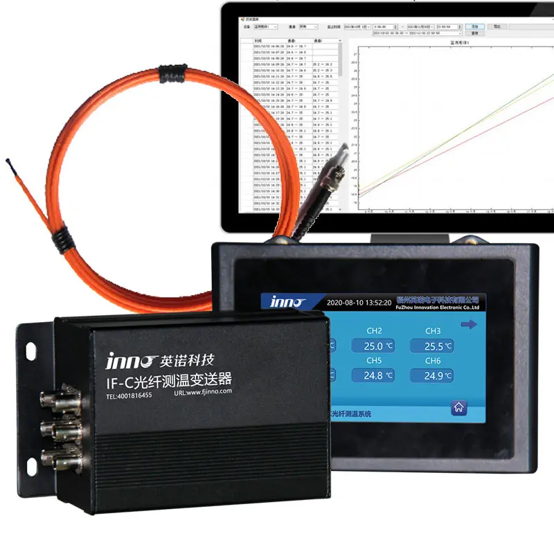
The system architecture combines precision temperature sensors, signal conditioning hardware, industrial communication interfaces, and supervisory platforms to deliver uninterrupted thermal visibility across the entire production environment.
Critical for preventing equipment failure, maximizing energy efficiency, and ensuring product quality, мониторинг температуры в режиме реального времени is a foundational element of modern industrial automation — from discrete manufacturing to continuous process industries.
Передовые сенсорные технологии, такой как флуоресцентные оптоволоконные датчики температуры, deliver high-accuracy, не требующий обслуживания, EMI-immune real-time measurement at multiple points simultaneously — meeting the demanding requirements of high-voltage, high-temperature, and electrically noisy industrial environments.
Real-time temperature data supports automated alarm triggering, protective equipment shutdown, cooling system regulation, process parameter optimization, and predictive maintenance analytics essential for operational reliability and safety compliance.
Industrial Fiber Optic Real-Time Temperature Monitoring System
Электронная почта: web@fjinno.net
WhatsApp: +8613599070393
Оглавление
- What Is Real-Time Temperature Monitoring?
- Why Real-Time Monitoring Is Superior to Periodic Measurement
- How Real-Time Temperature Monitoring Works: Архитектура системы
- Key Industrial Applications for Real-Time Temperature Monitoring
- Сенсорные технологии: Fiber Optic vs RTD vs Thermocouple vs Infrared
- Communication Protocols and SCADA/PLC Integration
- How to Choose a Real-Time Temperature Monitoring System for Industrial Automation
- Мониторинг температуры в реальном времени: Распространенные проблемы и решения
- Relevant International Standards for Industrial Temperature Monitoring
- Реальные примеры применения
- Benefits of Real-Time Temperature Analytics for Industrial Operations
- Future Trends in Real-Time Industrial Temperature Monitoring
- Часто задаваемые вопросы: Real-Time Temperature Monitoring in Industrial Automation
What Is Real-Time Temperature Monitoring?

Определение
Real-time temperature monitoring refers to the continuous acquisition, передача инфекции, and display of temperature measurements from industrial process points with minimal latency — typically less than 1 second from physical measurement to digital readout. Unlike periodic or manual measurement, real-time monitoring operates 24/7 without interruption, providing a constant stream of thermal data that reflects the actual operating condition of equipment and processes at every moment.
Why It Matters in Industrial Automation
Industrial processes generate, consume, and are affected by heat in ways that directly determine product quality, срок службы оборудования, потребление энергии, и безопасность. A temperature deviation of just a few degrees can cause metallurgical defects in a steel mill, degrade insulation in a high-voltage transformer, trigger thermal runaway in a chemical reactor, or reduce yield in a semiconductor fabrication process. Real-time monitoring provides the continuous thermal visibility that automated control systems require to maintain precise operating conditions and to detect — and respond to — abnormal conditions before they escalate into equipment damage, инциденты безопасности, or production losses.
Core Components of a Real-Time Monitoring System
A complete real-time industrial temperature monitoring system consists of four core elements: temperature sensing elements (оптоволоконные зонды, РДД, термопары, or infrared sensors) installed at critical measurement points; signal conditioning and demodulation hardware that converts raw sensor signals into calibrated temperature values; industrial communication interfaces (RS485 Modbus RTU, Ethernet/IP, ПРОФИБУС, или OPC UA) that transmit data to supervisory systems; and a monitoring platform — SCADA, DCS, ПЛК, or cloud-based analytics — that displays data, manages alarms, logs history, and triggers automated protective actions.
Why Real-Time Monitoring Is Superior to Periodic Measurement

Continuous Visibility vs Snapshot Data
Periodic measurement — whether manual handheld readings, scheduled patrol inspections, or timed data logging — captures only isolated snapshots of the thermal state. Between measurements, temperature excursions can develop, пик, and cause damage without detection. Real-time monitoring eliminates these blind periods entirely, ensuring that every thermal event is captured and evaluated as it occurs.
Время ответа
The value of temperature data is directly proportional to how quickly it can be acted upon. A real-time system with sub-second sensor response and automated alarm logic can trigger protective actions — equipment shutdown, cooling activation, load reduction — within seconds of an abnormal temperature event. Manual or periodic measurement introduces delays of minutes, часы, or days, during which a developing fault can progress from a minor anomaly to a catastrophic failure.
Trend Analysis and Early Warning
Real-time monitoring generates a continuous temperature time series for each measurement point. Automated trend analysis detects gradual changes — a bearing temperature that rises 0.5°C per week, a transformer winding that runs progressively warmer under the same load — that are invisible in periodic spot measurements. These trends provide early warning of developing faults weeks or months before failure occurs, enabling planned maintenance rather than emergency repair.
Automation Integration
Modern industrial automation systems — PLCs, DCS, SCADA — require continuous input data to execute closed-loop control. A PLC controlling a furnace zone temperature, a DCS managing a chemical reactor cooling system, or a BMS regulating battery pack thermal management all depend on real-time temperature feedback. Periodic measurement cannot support closed-loop control — it can only support manual observation and reaction. Real-time monitoring is not merely an improvement over periodic measurement; it is a fundamental requirement of automated industrial operations.
How Real-Time Temperature Monitoring Works: Архитектура системы
Этап 1 — Зондирование
Temperature sensors are installed at or near the measurement points — on motor windings, transformer hot spots, распределительные шины, reactor vessel walls, furnace zones, or production line equipment. The sensor converts thermal energy into a measurable signal: a change in optical fluorescence decay time (оптоволокно), a change in electrical resistance (РТД), a voltage generation at a bimetallic junction (термопара), or infrared radiation intensity (IR pyrometer). For electrically hazardous or high-EMI environments, оптоволоконные датчики температуры are the preferred choice due to their complete electrical isolation and electromagnetic immunity.
Этап 2 — Signal Conditioning and Demodulation
The raw sensor signal is processed by a dedicated signal conditioning unit or demodulator. For fiber optic sensors, the demodulation unit generates an excitation light pulse, receives the fluorescence response through the optical fiber, измеряет время затухания с высокой точностью, and converts it to a calibrated temperature value. For electrical sensors (РТД, термопара), the conditioning unit amplifies the signal, compensates for lead resistance and cold junction effects, applies linearization, and converts the analog signal to a digital temperature reading.
Этап 3 — Data Transmission
Calibrated temperature data is transmitted from the signal conditioning unit to the supervisory system via industrial communication protocols. The most common protocols in industrial automation include RS485 Modbus RTU for point-to-point and multi-drop connections, Modbus TCP/IP for Ethernet-based networks, PROFIBUS and PROFINET for Siemens-based automation environments, EtherNet/IP for Allen-Bradley and Rockwell systems, and OPC UA for vendor-neutral interoperability. ИННО fluorescent fiber optic temperature measurement devices output via RS485 Modbus RTU — the most widely supported protocol across all industrial automation platforms.
Этап 4 — Processing, Отображать, and Action
The supervisory platform — SCADA, DCS, ПЛК, or cloud-based monitoring system — receives real-time temperature data from all monitoring points. The platform performs several critical functions: live display of all temperatures on HMI screens and dashboards; comparison of each reading against configured alarm and trip thresholds; generation of audible and visual alarms when thresholds are exceeded; automatic triggering of protective actions (equipment shutdown, cooling activation, load shedding) via PLC or relay outputs; logging of all temperature data and events to a historical database for trend analysis, отчетность о соответствии, and predictive maintenance analytics.
Key Industrial Applications for Real-Time Temperature Monitoring
Power Transformers and Distribution Equipment
Power transformers generate heat in windings and core under load. Real-time monitoring of winding hot-spot temperature, температура масла, and tap changer contact temperature prevents insulation degradation, detects developing faults, and enables dynamic loading optimization. The same monitoring principle applies to switchgear, где fiber optic temperature monitoring for switchgear detects busbar and contact hotspots caused by loose connections or degraded contacts.
Electric Motors and Generators
Температура обмотки статора, температура подшипника, and cooling air temperature are critical parameters for large industrial motors and generators. Real-time monitoring prevents winding insulation failure — the leading cause of motor breakdown — and enables load optimization based on actual thermal conditions rather than conservative fixed limits.
Chemical and Petrochemical Reactors
Exothermic chemical reactions require precise temperature control to maintain product quality, prevent runaway reactions, and ensure process safety. Real-time multi-point monitoring of reactor vessel temperatures provides the continuous thermal feedback necessary for automated cooling control and safety interlock operation.
Furnaces and Kilns
Industrial furnaces and kilns operate at extreme temperatures requiring continuous monitoring of heating zone temperatures, refractory wall temperatures, and exhaust gas temperatures. Real-time data enables precise zone control for uniform heating, energy optimization, and refractory life extension.
Аккумуляторные системы хранения энергии (БЕСС)
Grid-scale and industrial battery storage systems require real-time internal temperature monitoring to detect thermal runaway onset, manage cooling systems, and ensure compliance with safety standards. Оптоволоконные системы контроля температуры are increasingly specified for BESS applications due to their dielectric construction, which eliminates short-circuit risk inside battery packs.
Semiconductor and Electronics Manufacturing
Semiconductor fabrication processes — including chemical vapor deposition, etching, and thermal oxidation — require temperature control within ±0.5°C or tighter. Real-time monitoring with high-accuracy sensors ensures process consistency and yield optimization across all production tools.
Food, Pharmaceutical, and Cold Chain Processing
Regulatory requirements for food safety (HACCP), pharmaceutical manufacturing (GMP), and cold chain logistics demand continuous, documented temperature monitoring with traceable accuracy. Real-time systems provide both the operational control and the compliance data trail required by auditors and regulators.
Дата-центры
Server rooms and data centers require continuous thermal monitoring to manage cooling systems, prevent equipment overheating, and optimize energy consumption. Real-time temperature mapping enables hot-aisle/cold-aisle optimization and dynamic cooling adjustment based on actual thermal loads.
Сенсорные технологии: Fiber Optic vs RTD vs Thermocouple vs Infrared

The choice of sensor technology for real-time industrial temperature monitoring has direct implications for measurement accuracy, надежность, безопасность, требования к техническому обслуживанию, и общая стоимость владения. The four principal technologies are compared below.
| Особенность | Флуоресцентный оптоволоконный датчик | РТД (Пт100 / Pt1000) | Термопара (Type K/J/T) | Инфракрасный (Бесконтактный) |
|---|---|---|---|---|
| Точность измерения | ±0.1 – 0.5°C | ±0.5 – 1°C | ±1 – 2°C | ±1 – 3°C (surface only) |
| ЭМИ / High Voltage Immunity | ✅ Fully immune (диэлектрик) | ❌ Susceptible (requires shielding) | ❌ Susceptible (requires shielding) | ✅ Immune (бесконтактный) |
| Electrical Safety in HV Environments | ✅ Fully dielectric — safe in HV | ⚠️ Requires isolation barriers | ⚠️ Requires isolation barriers | ✅ Non-contact — safe in HV |
| Контакт / Бесконтактный | Контакт (surface or embedded) | Контакт | Контакт | Бесконтактный (line of sight required) |
| Время ответа | < 1 второй | 2 – 10 секунды | 1 – 3 секунды | < 1 второй |
| Диапазон рабочих температур | -40°С до +260°С | -200от °С до +600 °С | -200°C to +1350°C | -40°C to +3000°C |
| Долгосрочная стабильность | ✅ Excellent (нет дрейфа) | ✅ Good | ⚠️ Moderate (дрейфовать со временем) | ⚠️ Requires emissivity calibration |
| Maintenance Requirement | ✅ Maintenance-free | Периодическая калибровка | Frequent calibration/replacement | Очистка линз, emissivity verification |
| Многоточечная возможность | ✅ Up to 64 каналов на единицу | Separate sensor per point | Separate sensor per point | One point per sensor (or scanning) |
| Hazardous Area Suitability | ✅ Intrinsically safe (no electrical energy at probe) | ⚠️ Requires Ex-rated housing | ⚠️ Requires Ex-rated housing | ⚠️ Requires Ex-rated housing |
| Срок службы | > 25 годы | 5 – 10 годы | 2 – 5 годы | 5 – 10 годы |
| Общая стоимость владения | ✅ Lowest (no calibration/replacement) | Умеренный | Выше (frequent replacement) | Moderate to High |
| Лучшее приложение | HV equipment, распределительное устройство, моторы, трансформаторы, аккумуляторные системы, опасные зоны | General process monitoring, tanks, трубопроводы | Высокотемпературные печи, kilns, exhaust systems | Moving surfaces, inaccessible targets, very high temperatures |
Заключение: For industrial automation applications involving high voltage, strong electromagnetic interference, взрывоопасная атмосфера, or safety-critical equipment, fluorescent fiber optic sensors offer the best combination of accuracy, безопасность, надежность, and lifecycle cost. RTDs remain the standard for general-purpose process monitoring. Thermocouples are preferred for very high-temperature applications above 260°C. Infrared sensors are best for non-contact measurement of moving or inaccessible surfaces. For a detailed technical comparison, обратитесь к fiber optic temperature measurement system FAQ.
Communication Protocols and SCADA/PLC Integration
RS485 Modbus RTU
The most widely used serial communication protocol in industrial temperature monitoring. RS485 Modbus RTU supports multi-drop bus topologies with up to 32 устройства (или 128 with repeaters) on a single bus, operates reliably over cable distances up to 1,200 metres, and is supported by virtually every PLC, DCS, and SCADA platform. All INNO fiber optic monitoring systems use RS485 Modbus RTU as their standard output protocol.
Modbus TCP/IP
The Ethernet-based variant of Modbus, widely used in modern automation networks. Modbus TCP/IP provides higher data throughput, supports standard Ethernet infrastructure, and enables direct connection to network-based SCADA and cloud platforms. RS485 Modbus RTU devices can be connected to TCP/IP networks via standard serial-to-Ethernet gateways.
ПРОФИБУС / ПРОФИНЕТ
Standard communication protocols in Siemens-based automation environments. ПРОФИБУС (fieldbus) and PROFINET (Ethernet-based) are used for integration with Siemens S7 PLCs and WinCC SCADA systems. Temperature monitoring devices with Modbus output can be integrated into PROFIBUS/PROFINET networks via protocol converters.
EtherNet/IP
The standard industrial Ethernet protocol for Rockwell Automation (Allen-Bradley) системы. Temperature data from Modbus-based monitoring devices is integrated into EtherNet/IP architectures via Modbus-to-EtherNet/IP gateways, enabling seamless data flow to ControlLogix and CompactLogix PLCs.
ОПЦ ЮА
The vendor-neutral, platform-independent communication standard increasingly adopted for Industry 4.0 and IIoT applications. OPC UA provides secure, structured data exchange between monitoring systems and higher-level analytics platforms, cloud services, and enterprise systems. Many modern SCADA platforms include native OPC UA client functionality, simplifying integration with Modbus-based field devices via OPC UA server gateways.
Integration Architecture Best Practice
The recommended integration architecture for a real-time temperature monitoring system connects fiber optic transmitters via RS485 Modbus RTU to the plant automation network. The PLC or DCS reads temperature values from Modbus registers, applies alarm logic and protective control actions at the local level, and forwards data to the SCADA/HMI for visualization and historical logging. For enterprise-level analytics and remote monitoring, data flows from SCADA to cloud platforms via OPC UA or MQTT. This layered architecture ensures real-time protective response at the field level while enabling advanced analytics at the enterprise level.
How to Choose a Real-Time Temperature Monitoring System for Industrial Automation
Selecting the optimal real-time temperature monitoring system requires systematic evaluation of the application environment, performance requirements, and integration constraints. Follow this step-by-step guide to make the right selection.
Шаг 1: Characterize the Measurement Environment
Identify the key environmental factors at each measurement point: operating temperature range, presence of high voltage or strong electromagnetic fields, explosive or corrosive atmosphere classification, physical accessibility for sensor installation and maintenance, and vibration or mechanical stress levels. These factors determine which sensor technologies are viable and which are excluded.
Шаг 2: Define Accuracy and Response Time Requirements
Determine the temperature accuracy required by the process or equipment protection standard — ±0.5°C for precision processes, ±1°C for general industrial monitoring, or ±2°C for non-critical applications. Define the maximum acceptable response time: sub-second for rapid thermal events (короткие замыкания, exothermic reactions), 1–5 seconds for general process monitoring, or longer for slow thermal processes.
Шаг 3: Determine the Number and Location of Monitoring Points
Identify all critical measurement locations across the installation — equipment hot spots, connection points, cooling system boundaries, ambient reference points, and process-critical zones. Count the total number of monitoring points to determine the required channel capacity. INNO multi-channel fluorescent fiber optic temperature measurement devices поддерживать 1 к 64 каналов на единицу, accommodating installations from a single piece of equipment to an entire production facility.
Шаг 4: Select the Appropriate Sensor Technology
Based on the environmental characterization from Step 1 and the performance requirements from Step 2, select the sensor technology that meets all requirements. For high-voltage equipment (трансформаторы, распределительное устройство, моторы), аккумуляторные системы, взрывоопасная атмосфера, or high-EMI environments, флуоресцентные оптоволоконные датчики are the correct choice. For general-purpose process monitoring without electrical hazards, RTDs provide reliable performance. For very high-temperature applications above 260°C, thermocouples or infrared sensors are required.
Шаг 5: Confirm Communication Protocol Compatibility
Verify that the monitoring system’s output protocol is compatible with your existing automation infrastructure — or that a suitable protocol converter is available. RS485 Modbus RTU is universally compatible and can be integrated into any PLC, DCS, or SCADA platform either directly or via standard gateways.
Шаг 6: Evaluate Total Cost of Ownership
Compare not only the initial purchase price but the full lifecycle cost including installation, калибровка, обслуживание, sensor replacement, and downtime. Fiber optic systems have higher initial cost than thermocouples or NTCs but require zero maintenance, zero recalibration, and zero sensor replacement over a 25+ year service life — delivering the lowest total cost of ownership for long-term industrial installations.
Шаг 7: Assess Supplier Capability and Support
Evaluate the monitoring system supplier’s technical support capability, OEM/ODM customization capacity, delivery timeline, and track record in your specific industry. Как преданный производитель оптоволоконных датчиков температуры, INNO provides custom probe design, private-label transmitters, firmware customization, and comprehensive technical support for system integration and commissioning.
Мониторинг температуры в реальном времени: Распространенные проблемы и решения
Even well-designed monitoring systems can encounter operational issues. The following guide covers the most common problems, their causes, and recommended solutions.
Проблема 1: Sensor Reading Jumps Erratically or Shows Noise
Возможные причины:
- Electromagnetic interference coupling into electrical sensor cables (НТЦ, РТД, термопара) from nearby VFDs, силовые кабели, or switching equipment
- Loose terminal connections causing intermittent contact
- Damaged or degraded sensor cable insulation
- Grounding issues creating ground loop interference
Рекомендуемое действие: Inspect and tighten all terminal connections. Route sensor cables away from power cables and EMI sources. Replace unshielded cables with shielded twisted-pair routed in separate conduit. Verify proper grounding at a single point. For persistent EMI-related noise, upgrade to fiber optic sensors, which are inherently immune to all electromagnetic interference regardless of the installation environment.
Проблема 2: Sensor Reading Deviates from Expected Value
Возможные причины:
- Sensor calibration drift (common with thermocouples after prolonged high-temperature exposure)
- Poor thermal contact between sensor and measurement surface
- Sensor installed at a location that does not represent the true process temperature (например, too far from the hot spot)
- Lead wire resistance error in RTD measurement (for long cable runs without compensation)
Рекомендуемое действие: Verify the sensor reading against an independent reference thermometer. Check sensor mounting and thermal contact — re-bond or re-clamp if necessary. For RTDs on long cable runs, confirm that 3-wire or 4-wire compensation is correctly configured. Recalibrate or replace drifted sensors. Fluorescent fiber optic sensors do not experience calibration drift — if deviation is suspected, check probe physical integrity and optical connection quality.
Проблема 3: Communication Loss Between Sensor Transmitter and SCADA/PLC
Возможные причины:
- RS485 bus wiring fault — broken conductor, reversed A/B lines, or missing bus termination resistor
- Modbus address conflict between multiple devices on the same bus
- Baud rate or parity mismatch between transmitter and PLC/SCADA
- Cable distance exceeding RS485 maximum (1,200 м) without repeater
- Power supply failure to the monitoring transmitter
Рекомендуемое действие: Verify power supply to the transmitter unit. Check RS485 wiring continuity and polarity (A/B lines). Confirm bus termination resistors are installed at both ends of the bus. Verify Modbus address, baud rate, and parity settings match on all devices. For bus lengths exceeding 1,200 м, install RS485 repeaters. Use a Modbus diagnostic tool to test register read/write from the PLC side.
Проблема 4: Alarm Triggers Frequently Under Normal Operating Conditions
Возможные причины:
- Alarm threshold set too close to normal operating temperature without adequate margin
- Sensor noise or measurement uncertainty causing readings to momentarily cross the threshold
- Process operating conditions have changed (increased load, higher ambient temperature) since alarm thresholds were originally configured
Рекомендуемое действие: Review and adjust alarm thresholds with appropriate margins above the expected maximum normal operating temperature. Implement alarm delay (time filter) to prevent momentary noise spikes from triggering alarms. Re-evaluate process operating conditions and update threshold settings if baseline conditions have changed. Consider implementing tiered alarm strategy: предупреждение, тревога, and trip at progressively higher thresholds.
Проблема 5: Historical Data Gaps in SCADA Log
Возможные причины:
- Communication interruptions between transmitter and SCADA
- SCADA historian database storage full or write failure
- Polling interval configured too long, missing short-duration thermal events
- Network congestion in Ethernet-based systems causing packet loss
Рекомендуемое действие: Monitor communication link quality and configure SCADA to alarm on communication loss. Ensure historian database has adequate storage and is properly maintained. Set polling interval appropriate to the process dynamics — 1 second for fast thermal events, 5–10 seconds for slow processes. For Ethernet networks, implement Quality of Service (QoS) prioritization for monitoring data traffic.
Проблема 6: Sensor Fails Prematurely in Harsh Environment
Возможные причины:
- Sensor exposed to temperatures exceeding its rated operating range
- Chemical attack on sensor housing or cable insulation from corrosive process media
- Mechanical damage from vibration, impact, or improper installation
- Moisture ingress into electrical sensor connections
Рекомендуемое действие: Verify that the sensor’s rated temperature and chemical compatibility match the actual installation conditions. Provide mechanical protection (трубопровод, armoured cable, protective housings) appropriate to the environment. Seal all electrical connections against moisture. For extreme environments, fiber optic probes with stainless steel or ceramic protective housings provide superior durability and chemical resistance, with no electrical connections exposed to the process environment.
Relevant International Standards for Industrial Temperature Monitoring
МЭК 61010 — Safety Requirements for Electrical Equipment for Measurement, Control, and Laboratory Use
МЭК 61010 defines safety requirements for measurement equipment including temperature monitoring instruments. Compliance ensures that the monitoring hardware meets international safety standards for electrical insulation, protection against hazardous voltage, and safe operation in industrial environments.
МЭК 60751 — Industrial Platinum Resistance Thermometers and Platinum Temperature Sensors
МЭК 60751 specifies accuracy classes and tolerance limits for platinum RTD sensors (Пт100, Pt1000). This standard defines Class A (±0,15°С + 0.002×|т|) and Class B (±0,3°С + 0.005×|т|) accuracy specifications that are referenced in industrial monitoring system design and procurement.
МЭК 60584 — Thermocouples
МЭК 60584 defines thermocouple types (K, Дж, Т, Н, С, Р, Б, Э), their electromotive force characteristics, and tolerance classes. This standard is referenced when specifying thermocouple-based monitoring for high-temperature industrial applications.
МЭК 62439 — Industrial Communication Networks — High Availability Automation Networks
МЭК 62439 addresses network redundancy and high availability for industrial automation communication. For critical real-time temperature monitoring installations where data loss is unacceptable, network architecture should comply with this standard to ensure continuous data availability.
МЭК 61508 — Functional Safety of Electrical/Electronic/Programmable Electronic Safety-Related Systems
МЭК 61508 provides the framework for safety integrity levels (SIL) in safety-related systems. When real-time temperature monitoring serves a safety function — such as triggering emergency shutdown of a reactor or transformer — the monitoring system must be designed and validated to the appropriate SIL level as defined by this standard.
ATEX Directive (2014/34/EU) and IECEx System
For monitoring equipment installed in explosive atmospheres (gas or dust), compliance with ATEX (Европейский) or IECEx (international) explosion protection standards is mandatory. Оптоволоконные датчики, which carry no electrical energy at the probe tip and cannot generate sparks, are inherently suitable for intrinsically safe installations in Zone 0, 1, и 2 опасные зоны.
ИСО 9001 — Quality Management Systems
ИСО 9001 certification of the monitoring system manufacturer ensures that design, производство, тестирование, and calibration processes follow documented quality management procedures. All INNO fiber optic monitoring products are manufactured under an ISO 9001 certified quality management system.
Реальные примеры применения
Тематическое исследование 1: High-Voltage Switchgear — Preventing Busbar Connection Failure
Application Background
А 110 kV substation experienced a busbar connection failure caused by a gradually degrading bolted contact that was not detected during quarterly thermal imaging inspections. The failure resulted in an arc flash event, significant equipment damage, and an unplanned outage affecting industrial customers. The utility required continuous real-time monitoring to prevent recurrence.
Решение реализовано
A multi-channel fiber optic temperature monitoring system for switchgear was installed across all high-voltage switchgear cabinets. Fiber optic probes were placed directly on each busbar connection, circuit breaker contact, and cable termination point. Temperature data was transmitted via RS485 Modbus RTU to the substation SCADA system with configurable alarm and trip thresholds.
Достигнутые результаты
Within six months of installation, the system detected a 7°C temperature elevation at a busbar connection in an adjacent switchgear cabinet — an early-stage fault identical to the one that had caused the previous failure. The connection was retorqued during scheduled maintenance at a cost of less than $200, preventing an estimated $500,000+ failure and weeks of unplanned downtime. The system has operated maintenance-free since installation.
Тематическое исследование 2: Power Transformer — Dynamic Loading Optimization
Application Background
А 50 MVA power transformer at an industrial facility was operating near its nameplate rating during peak demand periods. Conservative fixed load limits based on ambient temperature and nameplate data restricted the transformer’s capacity, requiring the facility to curtail production during peak demand or invest in an additional transformer.
Решение реализовано
А оптоволоконная система контроля температуры was installed to provide real-time winding hot-spot temperature, top oil temperature, и нижняя температура масла. The real-time thermal data was integrated with the facility’s power management system to implement dynamic transformer rating (ДТР) — adjusting the permissible load based on actual thermal conditions rather than conservative worst-case assumptions.
Достигнутые результаты
With actual winding temperature data, the transformer was safely loaded to 115% of nameplate during cool ambient conditions — eliminating production curtailment and deferring the $2M+ investment in an additional transformer by an estimated 5–7 years. The real-time data also revealed that the transformer’s cooling fans had degraded performance, prompting maintenance that restored cooling capacity and further increased the thermal margin.
Тематическое исследование 3: Chemical Process Plant — Reactor Temperature Safety Interlock
Application Background
A chemical manufacturer operating exothermic batch reactors required upgrade of their temperature-based safety interlock system. The existing thermocouple-based system suffered from EMI-induced measurement errors due to proximity to high-power agitator motor drives, and thermocouple drift required quarterly recalibration — during which the safety interlock had to be bypassed.
Решение реализовано
флуоресцентный оптоволоконные датчики температуры replaced the thermocouples at all reactor measurement points. The fiber optic probes were installed in existing thermowell fittings, requiring no modification to the reactor vessel. The multi-channel fiber optic transmitter was integrated with the reactor’s safety PLC via RS485 Modbus RTU.
Достигнутые результаты
EMI-induced measurement errors were completely eliminated — the fiber optic sensors are fully immune to electromagnetic interference from the agitator drives. The calibration-free operation of the fiber optic sensors eliminated the quarterly recalibration requirement and the associated safety interlock bypass. The plant’s functional safety assessment confirmed that the upgraded monitoring system met the required SIL 2 rating for the reactor temperature safety interlock function.
Benefits of Real-Time Temperature Analytics for Industrial Operations
Прогнозируемое обслуживание
Continuous real-time temperature data enables trend-based prediction of equipment degradation and failure. A motor bearing that exhibits a gradual temperature uptrend under consistent load conditions signals developing wear before vibration analysis can detect it. A transformer winding that responds to the same load with progressively higher temperatures indicates insulation degradation or cooling system decline. These predictive insights enable maintenance to be planned during scheduled windows — eliminating surprise failures, reducing repair costs, и продление срока службы оборудования.
Energy Efficiency Optimization
Real-time temperature data reveals energy waste that is invisible without continuous monitoring. Furnaces with uneven zone temperatures waste energy heating compensating zones. Cooling systems that operate at fixed settings regardless of actual thermal load consume excess energy. Motors running above optimal temperature due to misalignment or unbalanced loads consume more energy per unit of output. Real-time monitoring quantifies these inefficiencies and enables targeted corrective actions that reduce energy consumption — typically by 5–15% in facilities implementing comprehensive thermal analytics.
Product Quality Assurance
In manufacturing processes where temperature directly affects product quality — metals processing, food production, pharmaceutical manufacturing, polymer extrusion, semiconductor fabrication — real-time monitoring ensures that temperature stays within specification at every moment. This eliminates temperature-related quality defects, reduces scrap and rework, and provides documented evidence of process compliance for quality audits and customer certification requirements.
Operational Safety Enhancement
Real-time monitoring with automated alarm and protection logic provides continuous safety coverage that does not depend on operator vigilance, patrol schedules, or manual inspections. The system responds to thermal hazards at the speed of the control system — milliseconds for PLC-based trip logic — rather than at the speed of human recognition and reaction. This automated safety layer is essential for processes involving explosive materials, toxic chemicals, высоковольтное оборудование, and other environments where thermal excursions can have catastrophic consequences.
Regulatory Compliance and Documentation
Regulatory bodies, страховые андеррайтеры, and industry standards increasingly require documented evidence of continuous temperature monitoring and thermal protection. Real-time monitoring systems automatically generate the historical data logs, alarm event records, and trending reports needed for compliance documentation — eliminating the manual record-keeping burden and providing higher-quality evidence than periodic manual measurements.
Future Trends in Real-Time Industrial Temperature Monitoring
Industrial Internet of Things (IIoT) Интеграция
Real-time temperature monitoring systems are increasingly connected to IIoT platforms that aggregate data from multiple sites, apply cloud-based analytics, and provide remote monitoring via web and mobile interfaces. This trend enables centralized monitoring of distributed industrial assets — substations, pipeline networks, wind farm transformers, remote manufacturing facilities — from a single operations center.
Artificial Intelligence and Machine Learning
AI/ML algorithms trained on historical real-time temperature data can identify complex failure patterns, optimize process parameters, and predict remaining useful life with greater accuracy than threshold-based alarm logic alone. These algorithms continuously improve their predictive accuracy as more operational data is collected, transitioning from reactive alarming to proactive asset management.
Digital Twin Technology
Digital twins — real-time virtual models of physical equipment — use continuous temperature data as a primary input. A digital twin of a transformer, мотор, or reactor combines real-time thermal data with electrical, механический, and process data to create a comprehensive virtual replica that can be used for what-if analysis, оптимизация нагрузки, and failure prediction with higher fidelity than any single-parameter analysis.
Периферийные вычисления
Processing temperature data at the edge — in the monitoring transmitter or a local gateway rather than in a distant cloud server — reduces latency, enables faster protective responses, and reduces network bandwidth requirements. Edge computing is particularly important for safety-critical applications where sub-second response to thermal events is essential and cloud latency is unacceptable.
Wireless and Autonomous Sensor Networks
Advances in low-power wireless protocols (WirelessHART, ISA100.11a, ЛоРаВАН) are enabling wireless temperature sensor networks for applications where cable routing is impractical. Однако, for safety-critical monitoring of high-voltage or hazardous equipment, wired fiber optic sensors remain preferred due to their guaranteed communication reliability, immunity to wireless interference, and complete electrical isolation.
Sensor Miniaturization and Flexible Form Factors
Ongoing development in fiber optic sensor manufacturing is producing thinner, more flexible probes that can be installed in increasingly confined spaces — inside motor winding slots, between battery cells, within compact switchgear compartments — expanding the range of applications for high-accuracy real-time monitoring.
Часто задаваемые вопросы: Real-Time Temperature Monitoring in Industrial Automation
What is real-time temperature monitoring in industrial automation?
Real-time temperature monitoring is the continuous measurement and transmission of temperature data from industrial process and equipment points with sub-second latency. Unlike periodic manual readings or timed data logging, real-time monitoring operates 24/7, providing constant thermal visibility to automated control systems (ПЛК, DCS, СКАДА) and enabling instant detection and response to abnormal temperature conditions. It is a foundational capability of modern industrial automation.
What sensor technology is best for real-time industrial temperature monitoring?
The best sensor technology depends on the application environment. For high-voltage equipment, electrically hazardous environments, high-EMI areas, and safety-critical applications, флуоресцентные оптоволоконные датчики температуры are the superior choice due to their complete electrical isolation, иммунитет к электромагнитным помехам, and maintenance-free operation. RTDs are well-suited for general process monitoring. Thermocouples are preferred for very high temperatures above 260°C. Infrared sensors are used for non-contact measurement of moving or inaccessible surfaces.
How does a fiber optic temperature monitoring system integrate with my PLC or SCADA?
All INNO fluorescent fiber optic temperature measurement devices output calibrated temperature data via RS485 Modbus RTU — the most widely supported industrial communication protocol. Your PLC or SCADA system reads temperature values from standard Modbus holding registers. Integration requires only standard Modbus register mapping in the PLC/SCADA configuration — no special drivers or proprietary software are needed. For Ethernet-based systems, standard RS485-to-Ethernet gateways provide Modbus TCP/IP connectivity.
How many monitoring points can a single fiber optic system support?
INNO multi-channel fiber optic transmitters are available in configurations from 1 к 64 каналов на единицу. Each channel monitors one independent measurement point with individual alarm and trip threshold configuration. Multiple transmitters can be connected on the same RS485 bus, enabling systems with hundreds of monitoring points managed from a single SCADA station.
What is the accuracy of fiber optic temperature sensors for industrial monitoring?
Fluorescent fiber optic temperature sensors provide measurement accuracy of ±0.1°C to ±0.5°C across their operating range of -40°C to +260°C. This accuracy is maintained throughout the sensor’s entire service life of 25+ years without recalibration — a significant advantage over thermocouples and NTC thermistors, which experience calibration drift requiring periodic recalibration or replacement.
Can real-time temperature monitoring be retrofitted to existing industrial equipment?
Да. Fiber optic temperature probes can be retrofitted to existing equipment including transformers, распределительное устройство, моторы, реакторы, and battery systems. Probes are installed in existing sensor ports, thermowells, or cable entry points during scheduled maintenance. The monitoring transmitter is typically mounted in an existing control cabinet. Retrofit installation generally requires no equipment modification and no extended outage — installations are routinely completed during normal maintenance windows.
Is real-time temperature monitoring required by industrial standards?
Many industrial standards require or strongly recommend continuous temperature monitoring for critical equipment. МЭК 60076 requires winding temperature monitoring for large power transformers. МЭК 62271 requires temperature monitoring for high-voltage switchgear. UL 9540 and NFPA 855 require thermal monitoring for battery energy storage systems. МЭК 61508 requires continuous monitoring for safety-related functions. Compliance with these standards is often a prerequisite for equipment insurance, grid connection approval, and regulatory certification.
What is the service life of a fiber optic temperature monitoring system?
INNO fluorescent fiber optic monitoring systems are designed for a service life exceeding 25 годы. The fiber optic probes contain no electronics, no moving parts, and no materials subject to chemical degradation in normal industrial environments. The monitoring transmitter is solid-state with industrial-grade component specifications. The system requires zero maintenance, zero recalibration, and zero sensor replacement over its entire service life — delivering the lowest total cost of ownership of any temperature monitoring technology.
Can fiber optic sensors be used in explosive or hazardous atmospheres?
Да. Fiber optic temperature probes are inherently intrinsically safe because they carry no electrical energy — only light passes through the fiber. The probe cannot generate sparks, дуги, or surface temperatures capable of igniting gas or dust. This makes fiber optic sensors uniquely suitable for installation in ATEX/IECEx classified hazardous areas (Зона 0, 1, 2 for gas; Зона 20, 21, 22 for dust) without the explosion-proof enclosures and intrinsic safety barriers required by electrical sensors.
How do I get a quotation for an industrial real-time temperature monitoring system?
Contact INNO’s application engineering team through www.fjinno.net with your project details including equipment type, number of monitoring points, operating temperature range, условия окружающей среды (высокое напряжение, ЭМИ, классификация опасных зон), communication protocol requirements, and whether the installation is new or retrofit. A project-specific quotation including sensor selection, channel configuration, and system pricing is typically provided within 24 часы.
Отказ от ответственности: All product specifications, application examples, case results, and third-party references in this article are for general information purposes only and may be updated without notice. Actual product performance depends on installation conditions, operating environment, and system configuration. Brand names, standards references, and industry terms belong to their respective owners and are used for descriptive purposes only; no affiliation or endorsement is implied. Please contact the INNO sales team for a formal, project-specific quotation and technical confirmation before purchase. © 2011–2026 Fuzhou Innovation Electronic Scie&Компания Тех., ООО. Все права защищены.

Оптоволоконный датчик температуры, Интеллектуальная система мониторинга, Распределенный производитель оптоволокна в Китае
 |
 |
 |