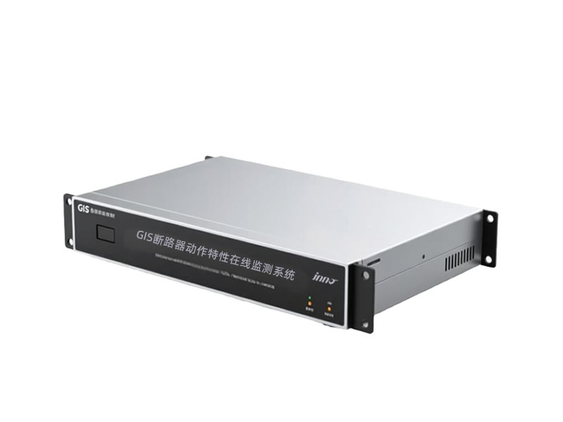
 Оптоволоконные датчики температуры INNO ,системы контроля температуры.
Распределительное устройство с газовой изоляцией (ГИС) стала основой современных сетей передачи и распределения электроэнергии по всему миру.. В качестве критически важных компонентов инфраструктуры, работающих под высоким напряжением., ГИС-оборудование требует постоянного мониторинга для предотвращения катастрофических сбоев, обеспечить эксплуатационную надежность, и оптимизировать стратегии обслуживания. В этом подробном руководстве рассматриваются ГИС-система предупреждения и мониторинга неисправностей, охватывающих технологии обнаружения, сенсорные архитектуры, протоколы связи, и практические стратегии реализации для коммунальных предприятий, операторы электростанции, и промышленные объекты.
- Основные сценарии применения: Подстанции сверхвысокого напряжения, городские распределительные сети, объекты электрогенерации, промышленные предприятия, морские ветряные платформы, и системы электрификации железных дорог
- Основные технические преимущества: Оценка состояния в режиме реального времени, раннее обнаружение неисправностей, возможности прогнозного обслуживания, сокращение времени простоя, расширенные протоколы безопасности, и соблюдение экологических норм
- Компоненты системной архитектуры: Многопараметрические сенсорные сети, intelligent data acquisition units, industrial communication infrastructure, centralized monitoring platforms, and automated alarm management systems
- Monitored Parameters: Частичный разряд, SF6 gas density and purity, распределение температуры, mechanical operating characteristics, содержание влаги, gas decomposition byproducts, и условия окружающей среды
- Communication and Data Infrastructure: МЭК 61850 protocol implementation, Modbus RTU/TCP connectivity, fiber optic networks, industrial Ethernet backbone, wireless telemetry options, and cybersecurity frameworks
- Warning and Alert Functions: Multi-level alarm hierarchies, threshold-based notifications, trend analysis warnings, распознавание аномальных образов, мобильные push-уведомления, и интеграция со SCADA-системами
- Преимущества обслуживания: Переход от обслуживания по времени к техническому обслуживанию по состоянию, увеличенный срок службы оборудования, оптимизированные графики проверок, снижение эксплуатационных расходов, повышенная надежность сети, и комплексные базы данных анализа отказов
1. Что такое ГИС (Распределительное устройство с газовой изоляцией)
1.1 Basic Concepts and Operating Principles of GIS
Распределительное устройство с газовой изоляцией (ГИС) represents a compact high-voltage electrical substation technology where all primary switching and protection equipment are enclosed in sealed metal compartments filled with sulfur hexafluoride (SF6) газ. The Изолирующий газ SF6 serves dual purposes: providing superior dielectric insulation strength approximately 2-3 times higher than air at atmospheric pressure, and acting as an arc-quenching medium during circuit breaker operations. Типичный GIS assembly integrates circuit breakers, отключить выключатели, заземлители, трансформаторы тока, трансформаторы напряжения, and busbars within a single metal-enclosed structure.
The operating principle relies on SF6 gas’s exceptional electrical properties. At pressures ranging from 0.4 к 0.6 МПа (4-6 bar), SF6 gas provides insulation equivalent to air at several times atmospheric pressure, enabling dramatic space reduction. The gas molecules possess excellent electron-capturing characteristics, rapidly neutralizing free electrons that could otherwise initiate electrical breakdown. During circuit breaker switching operations, the SF6 gas flow extinguishes the electrical arc through thermal and dielectric cooling processes, typically within milliseconds.
1.2 Development History of GIS Technology
The evolution of ГИС-технологии began in the 1960s when utilities faced increasing land costs and space constraints in urban areas. Early GIS installations operated at transmission voltages of 72.5 кВ до 145 кВ, primarily deployed in Japan and Europe. Throughout the 1970s-1980s, manufacturers expanded GIS capabilities to 245 кВ, 420 кВ, и 550 kV voltage classes, incorporating improved SF6 gas handling systems and enhanced insulator designs.
The 1990s witnessed significant technological advancements including the introduction of ultra-high voltage (сверхвысокое напряжение) ГИС rated at 800 кВ и 1100 kV for long-distance transmission projects in China, Япония, and Russia. Modern fourth-generation GIS equipment features modular construction, integrated monitoring capabilities, environmentally-friendly designs with minimal SF6 gas emissions, and digital secondary systems compatible with IEC 61850 communication standards.
1.3 GIS vs Traditional Air-Insulated Switchgear (АИС) Сравнение
| Comparison Parameter | ГИС (Распределительное устройство с газовой изоляцией) | АИС (Распределительное устройство с воздушной изоляцией) |
|---|---|---|
| Требования к пространству | Примерно 10-20% of equivalent AIS footprint; typical 245kV bay requires 40-60 m² | Extensive outdoor area needed; typical 245kV bay requires 300-500 m² |
| Место установки | Indoor or outdoor; ideal for underground substations, городские центры, морские платформы | Преимущественно наружная установка с достаточными зазорами. |
| Изоляционная среда | газ SF6 и 0.4-0.6 давление МПа; превосходная диэлектрическая прочность | Атмосферный воздух; требует больших зазоров между фазами и между фазами и землей. |
| Требования к техническому обслуживанию | Минимальный; герметичные отсеки предотвращают загрязнение; типичные интервалы проверки 5-10 годы | Требуется регулярное обслуживание; открытое оборудование, подверженное влиянию погодных условий, загрязнение, животные |
| Надежность и доступность | Высокая надежность (99.9%+); низкий уровень отказов; защищен от факторов окружающей среды | Погодозависимая надежность; вспышки во время загрязнения или суровых погодных условий |
| Соображения безопасности | Повышенная безопасность персонала; закрытые части под напряжением; уменьшенное воздействие вспышки дуги | Более высокие риски безопасности; открытые высоковольтные проводники; опасность проникновения птиц/животных |
| Первоначальные капитальные затраты | Более высокая стоимость оборудования; 1.5-2.5 раз стоимость оборудования АИС в зависимости от класса напряжения | Более низкая стоимость оборудования; более высокие затраты на строительные работы и приобретение земли в городских районах |
| Затраты жизненного цикла | Снижение совокупной стоимости владения; сокращение обслуживания, более высокая надежность, меньшая занимаемая площадь | Более высокие затраты на жизненный цикл в большинстве приложений; частое обслуживание, более широкое землепользование |
| Воздействие на окружающую среду | Контролируемые выбросы SF6 (мощный парниковый газ); современные конструкции сводят к минимуму утечку <0.5% ежегодно | Минимальные прямые выбросы; большее нарушение земель; визуальное воздействие в пейзажах |
| Сейсмические характеристики | Отличная сейсмостойкость; компактная жесткая конструкция; подходит для зон с высокой сейсмичностью | Более уязвимы к сейсмическим явлениям; несколько структур поддержки; более длинные проводники |
| Возможность расширения | Модульная конструкция позволяет контролируемое расширение; требует предварительного планирования дополнительных отсеков | Более простое горизонтальное расширение при наличии земли.; проще добавить оборудование |
| Электромагнитные помехи | Metal enclosures provide electromagnetic shielding; reduced EMI emissions | Higher electromagnetic field levels; potential interference with nearby electronics |
1.4 GIS Voltage Class Classifications
Medium voltage GIS operates at 12 кВ до 40.5 кВ, commonly deployed in industrial facilities, Коммерческие здания, and distribution substations. High voltage GIS ranges from 72.5 кВ до 170 kV for regional transmission networks. Сверхвысокое напряжение (сверхвысокое напряжение) ГИС spans 245 кВ до 550 kV for bulk power transmission. Ultra-high voltage (сверхвысокое напряжение) ГИС в 800 кВ и 1100 kV represents the pinnacle of current technology, utilized in China’s national transmission grid and select international projects requiring long-distance, high-capacity power delivery with minimal losses.
2. Основные области применения ГИС-оборудования
2.1 Extra-High Voltage and Ultra-High Voltage Substations
EHV and UHV transmission substations represent the most demanding application environment for GIS technology. При уровнях напряжения 245 кВ, 420 кВ, 550 кВ, 800 кВ, и 1100 кВ, GIS installations form the critical switching infrastructure for national and regional power grids. These substations typically feature multiple transformer bays, extensive bus configurations (double-bus, ring-bus, or breaker-and-a-half arrangements), and sophisticated protection schemes.
The ГИС-система мониторинга in EHV/UHV applications must address unique challenges including higher insulation stress levels, more severe consequences of equipment failure, and extended maintenance intervals due to accessibility constraints. Monitoring equipment specifications require enhanced sensitivity for partial discharge detection, high-precision SF6 density measurement with temperature compensation, and comprehensive mechanical diagnostics to detect subtle degradation in circuit breaker operating mechanisms before catastrophic failure occurs.
2.2 Urban Center Distribution Substations
Metropolitan areas face severe land constraints, изготовление compact GIS substations the preferred solution for 72.5 кВ до 145 kV distribution networks. These installations frequently occupy underground locations beneath parks, commercial developments, or transportation infrastructure. The indoor GIS configuration eliminates minimum clearance distance requirements, enables multi-story vertical construction, and provides weather-independent operation.
Urban GIS installations benefit significantly from системы онлайн-мониторинга because scheduled maintenance windows are difficult to obtain in networks serving critical loads such as hospitals, центры обработки данных, financial districts, and mass transit systems. Real-time monitoring enables condition-based maintenance strategies that maximize equipment availability while ensuring public safety in densely populated areas.
2.3 Power Generation Plant Switchyards
Повышение генератора (ГГУ) transformers and switchyard GIS at thermal, ядерный, hydroelectric, and renewable energy power plants handle the transition from generator voltage levels (обычно 13.8-24 кВ) to transmission voltages. These installations experience frequent switching operations during unit startup, synchronization, и последовательность выключения, плюс непрерывная работа при установившейся генерации.
The Требования к ГИС-мониторингу на генерирующих объектах особое внимание уделяется отслеживанию механического износа автоматических выключателей и разъединителей, контроль температуры сильноточных соединений, и оценка качества газа SF6. На многих заводах внедрены интегрированные системы мониторинга, которые соотносят данные о производительности ГИС с рабочими параметрами генератора., нагрузка трансформатора, и инструкции по диспетчеризации сети для оптимизации графика технического обслуживания в связи с запланированными отключениями электроэнергии..
2.4 Промышленные системы распределения электроэнергии
Крупные промышленные комплексы, включая сталелитейные заводы, нефтехимические заводы, цементные заводы, горнодобывающие работы, и производственные мощности развернуты КРУЭ среднего напряжения (12-40.5 кВ) для входящих служебных каналов, внутренние генерационные соединения, и распределение критической технологической нагрузки. The compact footprint suits plant environments where production floor space carries high economic value.
Industrial GIS monitoring systems integrate with plant distributed control systems (DCS) and manufacturing execution systems (MES) to coordinate electrical switching with production processes. Monitoring priorities include rapid fault detection to minimize production disruptions, contamination prevention in clean manufacturing environments, and safety compliance in hazardous areas where explosive atmospheres may exist.
3. Распространенные виды и механизмы отказа ГИС
3.1 Insulation Failure Categories
3.1.1 Partial Discharge Degradation
Частичный разряд (ПД) активность represents localized electrical discharges that partially bridge the insulation between conductors without causing complete breakdown. PD occurs at defect sites including sharp metallic protrusions, free conducting particles, insulator surface contamination, or gas voids in solid insulation. Each discharge event deposits energy that gradually erodes insulating materials through electrochemical processes and thermal effects.
The PD degradation mechanism accelerates over time as initial micro-damage creates increasingly favorable conditions for discharge activity. Common PD sources in GIS include manufacturing defects (metal particles left during assembly), installation problems (contamination introduced during commissioning), and operational stress (mechanical vibration loosening internal components). UHF partial discharge monitoring detects these defects years before they progress to complete insulation failure, enabling planned interventions during scheduled outages rather than forced emergency repairs.
3.1.2 SF6 Gas Decomposition Effects
During electrical discharge events or thermal faults, SF6 gas decomposes into various byproducts including sulfur tetrafluoride (SF4), sulfur dioxide (SO2), thionyl fluoride (SOF2), and sulfuryl fluoride (SO2F2). These compounds react with trace moisture to form hydrofluoric acid (ВЧ) and other corrosive substances that attack insulator surfaces, металлические компоненты, and sealant materials.
The presence of SF6 decomposition products indicates active or recent discharge activity. Monitoring systems detect these gases at parts-per-million concentrations, providing chemical evidence of insulation problems that may not yet produce detectable partial discharges under normal operating voltage. Gas analysis complements electrical PD detection methods, offering convergent evidence for diagnostic decision-making.
3.2 Mechanical Failures
3.2.1 Operating Mechanism Malfunctions
Механизмы управления выключателем использовать подпружиненный накопитель энергии, гидравлические системы, или пневматические приводы для управления подвижными контактами во время операций открытия и закрытия.. Механические неисправности возникают из-за ухудшения качества смазки., весенняя усталость, утечка через уплотнение в гидравлических/пневматических системах, износ сцепления, или неисправность регулирующего клапана.
Симптомы механизм деградации включать увеличение времени работы, уменьшенная скорость перемещения контакта, неполное завершение инсульта, и чрезмерное рабочее энергопотребление. Механические системы мониторинга отслеживать кривые времени в пути, измерить токи рабочих катушек, и анализировать признаки вибрации для выявления развивающихся проблем до того, как они приведут к отказу выключателя в работе. (ФТО) или неудача в поездке (ФТТ) события во время критических операций переключения.
3.2.2 Контактный износ и эрозия
Дугогасящие контакты В автоматических выключателях GIS происходит эрозия материала во время каждой операции переключения из-за электрической дуги высокой энергии, которая образуется при размыкании контактов под нагрузкой.. Контактные материалы (обычно медь-вольфрам или другие сплавы тугоплавких металлов.) постепенно испаряться и откладываться на поверхностях изолятора, потенциально создавая проводящие пути.
The скорость эрозии контактов зависит от величины коммутируемого тока, общее количество операций, коэффициент мощности цепи, и переключение рабочего цикла. Системы мониторинга отслеживают совокупные операции и коммутируемые ампер-часы для оценки оставшегося срока службы контактов.. Мониторинг температуры обнаруживает аномальный нагрев из-за увеличения контактного сопротивления по мере прогрессирования эрозии., возможность упреждающей замены контактов во время планового технического обслуживания.
3.3 Утечка газа SF6
Утечка газа SF6 снижает прочность изоляции и отключающую способность, potentially leading to equipment failure if gas density falls below minimum operating thresholds. Leak sources include seal degradation at bolted flanges, gasket compression set over time, micro-cracks in welds or castings, valve stem packing wear, and corrosion-induced pitting of metal enclosures.
Современный GIS leak rate specifications typically mandate less than 0.5% annual leakage per sealed compartment. Online gas density monitoring systems continuously track pressure and temperature, calculating real-time density values and detecting leaks within days rather than waiting months between manual inspections. Environmental SF6 concentration sensors detect major leaks immediately, activating ventilation systems and personnel alarms to prevent asphyxiation hazards in confined GIS rooms.
3.4 Overheating Failures
Thermal faults in GIS originate from high-resistance connections at bolted joints, inadequate contact pressure at sliding contacts, eddy current heating in enclosures, or localized insulation degradation. Unlike air-insulated equipment where visual inspection reveals discolored connections, GIS thermal problems develop hidden inside sealed compartments.
Системы контроля температуры using fiber optic sensors or wireless temperature transmitters installed on critical connection points detect temperature rise trends before permanent damage occurs. Advanced installations employ distributed temperature sensing fiber optic cables that provide continuous temperature profiles along busbars and across multiple connection points, identifying hotspots with meter-level spatial resolution.
4. Компоненты и структура ГИС-оборудования
4.1 Primary Electrical Equipment
4.1.1 Circuit Breaker Units
GIS circuit breakers employ puffer-type or self-blast arc interruption mechanisms utilizing SF6 gas flow to extinguish switching arcs. The puffer breaker design uses a mechanically-driven piston to compress SF6 gas during opening operations, directing high-velocity gas flow across the separating contacts to cool and de-ionize the arc column. Self-blast breakers utilize arc energy itself to heat and pressurize SF6 gas in a heating volume, creating pressure differentials that drive gas flow through the arc region.
Современный dead-tank GIS breakers поместите все токоведущие части в заземленные металлические корпуса., повышение безопасности и обеспечение непосредственной близости к соседнему оборудованию. The прерыватель содержит подвижные и неподвижные контакты, сопла контроля дуги, и изолирующие насадки, формирующие картину потока газа. Требования к мониторингу сосредоточены на механических характеристиках перемещения., рабочее энергопотребление, контактное сопротивление, и обнаружение частичного разряда в зоне прерывателя.
4.1.2 Разъединители и селекторные переключатели
Выключатели-разъединители (изоляторы) в ГИС обеспечивают видимые точки изоляции, когда работы по техническому обслуживанию требуют обесточивания определенного оборудования.. В отличие от автоматических выключателей, Выключатели-разъединители не могут прерывать ток нагрузки или ток повреждения.; они срабатывают только после того, как автоматические выключатели прервали ток и создали состояние нулевого тока.. The трехпозиционный выключатель design common in ring-bus configurations enables selection between alternative circuit paths.
Motor-operated disconnect switches employ electric motors with gear reduction mechanisms to drive the moving contacts through their travel. Системы мониторинга track motor current profiles during operation to detect mechanical binding, lubrication problems, or limit switch misalignment. Position indication sensors verify full open, средний, or full closed positions, with interlocking circuits preventing unsafe operating sequences.
4.1.3 Busbar Systems
GIS busbars comprise aluminum or copper tubular conductors encased in grounded metal enclosures, forming the main and transfer bus configurations. The three-phase separate-enclosure design isolates each phase conductor in its own gas compartment, preventing multi-phase faults and enabling independent maintenance. Common-enclosure designs house all three phases within a single large-diameter enclosure, offering space savings at the cost of reduced fault isolation.
Busbar monitoring emphasizes измерение температуры at expansion joints, bolted connections, and current transformer mounting points where contact resistance may increase over time. Датчики частичного разряда mounted on busbar enclosures detect PD activity from particles or protrusions on the conductor surface or enclosure interior.
4.2 Insulation Systems
The GIS insulation system combines SF6 gas insulation with solid insulator supports. Post insulators made from cast epoxy resin or porcelain support high-voltage conductors within the grounded metal enclosure. These insulators withstand both continuous operating voltage stress and transient overvoltages from switching operations or lightning impulses.
Insulator surface condition critically affects GIS reliability. Contamination from metal particles, condensed moisture, or SF6 decomposition products reduces insulator flashover voltage. УВЧ датчики mounted near major insulators detect partial discharges occurring on insulator surfaces, пока мониторинг влажности prevents water condensation that could create conducting films on insulator surfaces during temperature fluctuations.
4.3 Operating Mechanisms
Spring-charged mechanisms represent the most common operating mechanism type for GIS circuit breakers. Motors charge powerful compression or torsion springs over several seconds, storing energy for release during breaker closing operations. The stored energy drives contacts closed rapidly (обычно 60-100 milliseconds total operating time), then re-compresses opening springs that will drive the subsequent opening operation.
Hydraulic mechanisms used in high-voltage and UHV breakers employ hydraulic pumps to maintain pressure in accumulators. Pressure energy releases through control valves to drive hydraulic cylinders connected to the interrupter moving contacts. Системы мониторинга track hydraulic pressure levels, pump motor duty cycles, and control valve operation to detect seal leakage, нефтяное загрязнение, or valve sticking before mechanism failure occurs.
4.4 Gas Handling Systems
The SF6 gas system includes gas storage cylinders, vacuum pumps for evacuation during commissioning, gas filling manifolds with pressure regulation, moisture filters to remove water vapor, and transfer lines connecting storage to GIS compartments. Gas quality specifications mandate moisture content below 150 parts per million by volume (ppmv) and oxygen content below 100 ppmv to prevent insulator tracking and internal corrosion.
Online gas monitoring continuously measures SF6 density (mass per unit volume) which determines both dielectric strength and interrupting capacity. Temperature compensation circuits correct pressure readings to calculate true density independent of ambient temperature variations. Gas purity sensors обнаружить загрязнение воздуха из-за утечки через уплотнение, пока датчики влажности отслеживать концентрацию водяного пара, чтобы предотвратить конденсацию в холодную погоду.
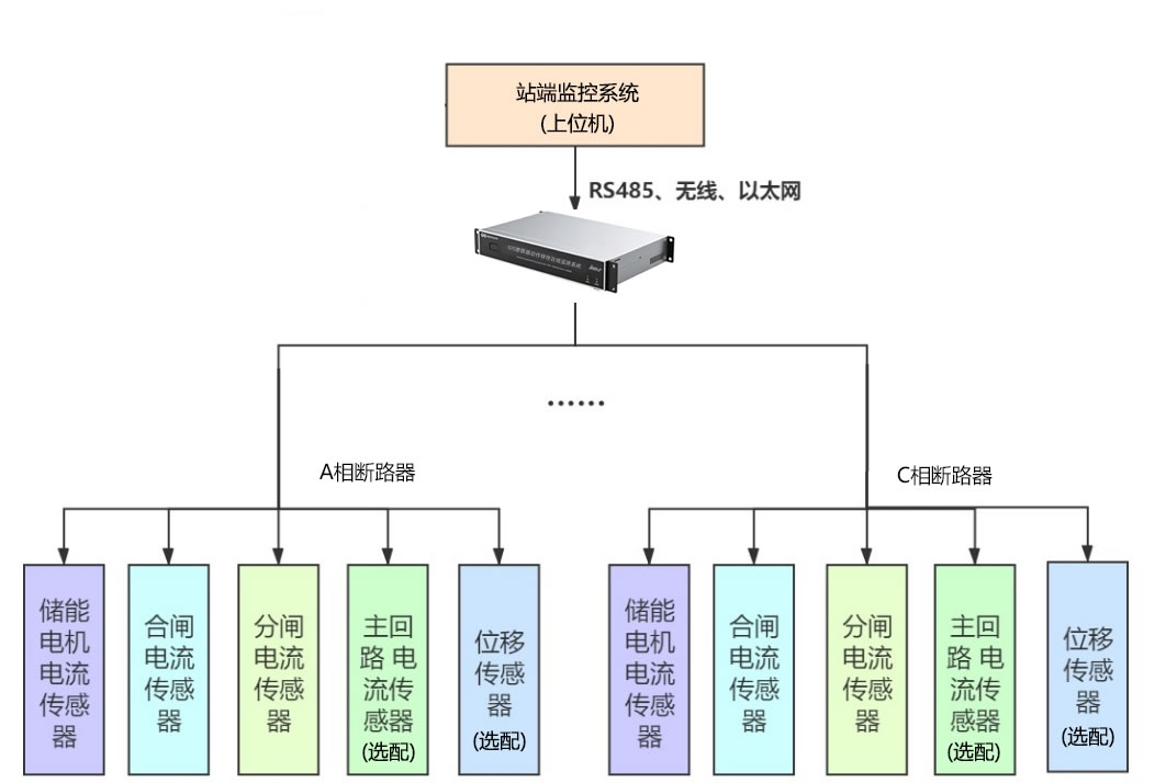
5. Архитектура и компоненты системы ГИС-мониторинга
5.1 Общая архитектура системы
Комплексный ГИС-система мониторинга состояния использует иерархическую архитектуру, состоящую из сенсорных сетей, интеллектуальные блоки сбора данных, инфраструктура связи, и платформы централизованного анализа. The сенсорный слой распределяет специализированные датчики по всей установке КРУЭ для измерения электрических, механический, химический, и тепловые параметры. The слой обработки края размещает интеллектуальные электронные устройства (СВУ) которые оцифровывают сигналы датчиков, выполнить локальный анализ, и общаться вверх по промышленным протоколам.
The уровень связи реализует оптоволоконные сети, промышленные коммутаторы Ethernet, или беспроводная телеметрия для агрегирования данных от распределенных интеллектуальных электронных устройств в системы автоматизации подстанций и центры мониторинга предприятия.. The прикладной уровень обеспечивает человеко-машинный интерфейс, диагностические алгоритмы, управление тревогами, исторические тенденции, и интеграция с базами данных управления активами. Эта архитектура обеспечивает как мониторинг в реальном времени для немедленного обнаружения неисправностей, так и долгосрочный анализ для профилактического планирования технического обслуживания..
5.2 Категории сенсорных технологий
5.2.1 Датчики частичного разряда
Сверхвысокая частота (УВЧ) антенны обнаруживать электромагнитное излучение, испускаемое во время событий частичного разряда. Эти датчики крепятся к диэлектрическим окнам, установленным в корпусах КРУЭ, или подключаются к коаксиальным портам мониторинга с элегазовой изоляцией.. The Полоса обнаружения УВЧ обычно охватывает 300 МГц до 3 ГГц, улавливание переходных сигналов со временем нарастания в наносекундном диапазоне и подавление низкочастотных электромагнитных помех, возникающих при работе энергосистемы.
Датчики акустической эмиссии реагировать на ультразвуковые волны давления, генерируемые событиями частичного разряда, распространяющимися через газ SF6 и структуры КРУЭ. Piezoelectric transducers mounted on external enclosure surfaces detect these mechanical vibrations in the 20-300 kHz frequency range. The multi-sensor array approach enables triangulation algorithms to locate PD sources along busbar runs or within complex bay configurations by measuring time-of-arrival differences between sensors.
5.2.2 Temperature Sensing Devices
Оптоволоконные датчики температуры utilizing fluorescence decay principles provide immunity to electromagnetic interference, electrical isolation from high-voltage conductors, and suitability for direct mounting on energized components. The fluorescent crystal sensor embedded in the fiber tip emits light when excited by an optical pulse, with decay time temperature-dependent. Measurement electronics analyze this decay characteristic to calculate temperature with ±1°C accuracy.
Wireless battery-powered temperature transmitters mount directly on high-voltage conductors, measuring local temperature and transmitting data via radio frequency signals through the grounded enclosure. Power harvesting from the magnetic field surrounding current-carrying conductors enables decades-long operation without battery replacement, пока antenna coupling techniques allow signal transmission through small apertures in the grounded enclosure.
5.2.3 SF6 Gas Monitoring Instruments
Online density monitors incorporate pressure transducers and temperature sensors with microprocessor-based calculation to provide continuous SF6 density measurement. The density algorithm applies real gas equations of state rather than ideal gas assumptions, achieving accuracy within ±1% across wide temperature ranges. Integrated data logging captures density trends, leak rate calculations, and alarm event time-stamps.
Gas quality analyzers employ multiple sensing technologies to assess SF6 purity and contamination. Oxygen sensors using galvanic cell or zirconium oxide technologies detect air ingress. Датчики влажности based on capacitance or aluminum oxide impedance measurement track water vapor concentration. Decomposition product sensors utilize electrochemical cells or infrared absorption spectroscopy to quantify SOF2, SO2F2, and other breakdown byproducts at parts-per-million sensitivity.
5.2.4 Mechanical Characteristic Sensors
Linear displacement transducers employing magnetostrictive or optical encoding principles measure circuit breaker contact travel with sub-millimeter resolution. The travel-time recorder captures complete stroke profiles during opening and closing operations, enabling calculation of average velocity, maximum velocity, contact acceleration, and stroke consistency between phases.
Вибрационные акселерометры установленные на рабочих механизмах обнаруживают механические признаки, связанные с конкретными компонентами механизма. Анализ частотного спектра определяет характерные частоты зацепления зубчатых колес., защелка, буферные воздействия, и подшипниковые резонансы. Изменения в шаблоны вибрации указывают на развивающиеся механические неисправности, такие как нарушение смазки, весенняя усталость, или износ рычажного механизма задолго до того, как эти условия приведут к сбоям в работе.
5.3 Инфраструктура сбора и обработки данных
Интеллектуальные электронные устройства (СВУ) служить узлами периферийных вычислений в системах ГИС-мониторинга. Каждое IED взаимодействует с несколькими датчиками., обеспечение аналого-цифрового преобразования, цифровая обработка сигналов, сравнение порогов, и запись событий. The IED-процессор локально выполняет диагностические алгоритмы, reducing communication bandwidth requirements by transmitting only processed diagnostic results and alarm notifications rather than continuous raw sensor data streams.
High-speed data acquisition modules for partial discharge monitoring employ sampling rates of 100 Мс/с до 1 GS/s (mega-samples per second to giga-samples per second), capturing UHF transient waveforms with sufficient fidelity for pulse shape analysis and phase-resolved pattern recognition. Waveform analysis algorithms extract parameters including pulse amplitude, rise time, частота повторений, and phase relationship to the power frequency voltage cycle, building pattern databases for PD source classification.
5.4 Коммуникационная и сетевая архитектура
The substation communication network typically implements a redundant fiber optic ring topology connecting monitoring IEDs to substation gateway servers. Station-level switches provide Gigabit Ethernet connectivity with IEEE 1588 Протокол точного времени (ПТП) synchronization ensuring microsecond-level time alignment across distributed sensors. This time synchronization enables accurate sequence-of-events recording and traveling wave fault location.
Protocol conversion gateways translate between monitoring system native protocols (often Modbus TCP or proprietary formats) and substation automation standard IEC 61850, enabling integration with protective relaying, СКАДА-системы, and utility enterprise networks. The communication security architecture implements VLANs to segregate monitoring traffic from protection and control networks, firewall rules to control data flows, and encrypted tunnels for wide-area communications to centralized monitoring centers.
6. Основные преимущества систем ГИС-мониторинга
6.1 Переход от обслуживания по времени к техническому обслуживанию по состоянию
Традиционный time-based maintenance strategies schedule GIS inspections and component replacements at fixed calendar intervals (например, 5-year major inspections, 10-year overhauls) regardless of actual equipment condition. This approach results in unnecessary maintenance on healthy equipment and potential failures of degraded equipment between scheduled interventions. Техническое обслуживание по состоянию (МУП) enabled by continuous monitoring shifts this paradigm by performing maintenance actions based on actual measured condition rather than elapsed time.
The CBM implementation monitors degradation trends, comparing real-time parameters against baseline values and threshold limits. Maintenance activities trigger when monitored conditions indicate developing problems, optimizing maintenance timing to prevent failures while avoiding premature component replacement. This approach extends equipment service life, снижает затраты на техническое обслуживание, and improves grid reliability by addressing actual rather than assumed degradation.
6.2 Early Fault Warning Capabilities
Progressive fault development in GIS typically follows detectable stages before catastrophic failure. Partial discharge activity increases gradually over months or years as insulation degrades. Contact resistance rises incrementally as erosion accumulates. Mechanical wear produces subtle changes in operating characteristics long before complete mechanism failure. Системы онлайн-мониторинга detect these early warning signs, providing maintenance windows measured in weeks or months rather than hours or minutes.
The early detection advantage enables planned outage scheduling during low-demand periods, procurement of necessary spare parts, mobilization of specialized maintenance crews, and preparation of temporary supply arrangements to maintain service to critical customers. This contrasts sharply with emergency response to unexpected failures requiring immediate forced outages, часто в периоды пиковой нагрузки при ограниченном наличии запасных частей и недостаточном времени на подготовку.
6.3 Продление срока службы оборудования
Жизнь проекта ГИС обычно варьируется от 30 к 40 лет при нормальных условиях эксплуатации при соответствующем обслуживании. Однако, Фактический срок службы сильно зависит от уровня рабочих нагрузок, условия окружающей среды, и качество обслуживания. Системы мониторинга продлевают срок службы путем обнаружения условий, которые ускоряют старение (перегрев, загрязнение влагой, чрезмерная активность ПД) при этом их можно исправить с помощью незначительных вмешательств, таких как повторная затяжка соединений., переработка газа, или локальная чистка.
The методология продления жизни сочетает непрерывную оценку состояния с целенаправленными мерами по исправлению ситуации, предотвращение перехода незначительной деградации к серьезным сбоям, требующим полной замены компонентов. Statistical analysis of monitoring data from large equipment populations enables refinement of maintenance procedures, identification of design vulnerabilities requiring manufacturer feedback, and optimization of spare parts inventory based on actual rather than theoretical failure rates.
6.4 Power Supply Reliability Enhancement
Grid reliability metrics including System Average Interruption Duration Index (SAIDI) and System Average Interruption Frequency Index (SAIFI) improve measurably when utilities implement comprehensive GIS monitoring. Forced outage reduction results from early detection and planned correction of developing faults. The monitoring system’s contribution to reliability becomes particularly significant in applications serving critical infrastructure such as hospitals, центры обработки данных, аварийные службы, and mass transportation systems.
Operational flexibility increases as monitoring provides real-time equipment health visibility, enabling confident loading to design limits rather than conservative operation with excessive safety margins. During contingency conditions (forced outages elsewhere in the network), monitoring confirms that temporary overload conditions remain within acceptable thermal and electrical stress levels, maximizing transmission capacity utilization during emergencies.
6.5 Historical Data Analysis and Diagnostic Insights
Long-term trending analysis of monitoring data reveals degradation patterns invisible in snapshot measurements. Gradual increases in partial discharge magnitude, progressive moisture accumulation, or slowly rising connection temperatures become apparent only when examining months or years of historical data. Database analytics correlate equipment condition with operating history (профили нагрузки, switching frequency, условия окружающей среды) to identify causal relationships and refine predictive models.
The fleet-wide analysis capability aggregates data from multiple similar GIS installations across a utility’s service territory or an equipment manufacturer’s global installed base. Statistical methods identify outliers requiring investigation, establish realistic performance benchmarks, and quantify the impact of design modifications or maintenance procedure changes. This collective intelligence accelerates learning and continuous improvement far beyond what individual site analysis could achieve.
7. Сравнение технологий обнаружения частичных разрядов
| Технология обнаружения | Принцип работы | Sensitivity Level | Localization Capability | Noise Immunity | Типичные применения |
|---|---|---|---|---|---|
| Сверхвысокая частота (УВЧ) | Обнаруживает электромагнитное излучение (300 МГц – 3 ГГц) emitted during PD events using antennas coupled to GIS enclosures | Отличный: detects PD <5 pC in favorable conditions; typical threshold 10-20 ПК | Очень хороший: time-of-flight triangulation with multiple sensors locates sources within ±1-2 meters | Отличный: high-frequency operation rejects power frequency interference and radio broadcasts | Primary method for GIS; suitable for online continuous monitoring; effective in electrically noisy environments |
| Акустическая эмиссия (АЕ) | Detects ultrasonic pressure waves (20-300 кГц) generated by PD events using piezoelectric sensors on external surfaces | Хороший: detects moderate to severe PD (обычно >50 ПК); sensitivity degrades with distance from source | Хороший: triangulation possible with sensor arrays; accuracy ±5-10 meters depending on GIS structure complexity | Умеренный: sensitive to mechanical vibration, pump noise, transformer hum; digital filtering required | Complementary to UHF; эффективен для локализации известных дефектов; полезно во время пуско-наладочных проверок |
| Переходное напряжение заземления (ТЭВ) | Измеряет импульсы напряжения на внешних поверхностях корпуса КРУЭ, вызванные емкостной связью с внутренними событиями частичного разряда. | Умеренный: обнаруживает значительную активность ПД (обычно >100 ПК); чувствительность зависит от геометрии корпуса | Ограниченный: указывает, в какой секции корпуса находится PD; точное местоположение требует пешеходной съемки с помощью портативного датчика | Умеренный: восприимчив к внешним электромагнитным помехам; экранирование и фильтрация улучшают производительность | Портативные геодезические приборы для периодической проверки; быстрый скрининг для выявления проблемных отсеков, требующих детального изучения |
| Химическое обнаружение (Газовый анализ) | Анализирует продукты разложения SF6. (SOF2, SO2F2, и т. д.) с использованием газовой хроматографии или электрохимических датчиков | Отлично подходит для побочных химических продуктов.: обнаруживает продукты разложения на уровне ppm, что указывает на продолжительную активность разряда | Бедный: gas samples represent entire sealed compartment; cannot pinpoint discharge location within compartment | Отличный: невосприимчив к электрическим помехам; химический анализ дает убедительные доказательства разряда или термической неисправности. | Периодический отбор проб во время простоев технического обслуживания; онлайн-датчики для критически важных установок; подтверждает результаты обнаружения электрических частичных разрядов |
| Высокочастотный трансформатор тока (ВФКТ) | Измеряет высокочастотные импульсы тока в заземлителях КРУЭ с помощью катушек Роговского или трансформаторов тока. | От среднего до хорошего: detects PD >20-50 ПК в зависимости от положения датчика и конфигурации заземления | Ограниченный: определяет, какой заземляющий проводник несет сигналы частичного разряда; несколько датчиков улучшают идентификацию зон | Хороший: полосовая фильтрация (3-30 Типичное значение МГц) подавляет частоту сети и многие источники помех | Приложения для модернизации, где проникновение в корпус датчиков УВЧ нецелесообразно.; контролирует целостность цепи заземления |
7.1 Сверхвысокая частота (УВЧ) Метод обнаружения
7.1.1 Принципы работы УВЧ и характеристики сигнала
Обнаружение частичных разрядов УВЧ exploits the fact that rapid charge movement during PD events generates electromagnetic radiation with frequency content extending into the UHF spectrum (300 МГц до 3 ГГц). The PD current pulse has extremely fast rise time (обычно <1 nanosecond), producing a broadband electromagnetic spectrum. GIS metal enclosures act as waveguides, propagating these UHF signals along the structure with relatively low attenuation compared to lower frequencies.
The Датчик УВЧ consists of an antenna element coupled to the SF6 gas space through a dielectric window or specialized monitoring port in the GIS enclosure. Commercial sensor designs include internal disk antennas installed through standard GIS viewing ports, external patch antennas coupled through dielectric spacers, and integrated sensors built into insulator supports. The signal processing chain amplifies the received UHF signal, applies bandpass filtering to optimize signal-to-noise ratio, and digitizes waveforms for subsequent analysis.
7.1.2 UHF Sensor Types and Installation Methods
Internal UHF sensors provide optimal coupling to PD sources because the antenna resides within the SF6 gas environment where discharge events occur. Installation requires access to GIS compartments through existing inspection ports or custom-designed monitoring windows. The dielectric window material (typically cast epoxy or fiberglass) allows electromagnetic wave transmission while maintaining pressure containment and insulation integrity.
External UHF sensors mount on the outside of GIS enclosures, detecting electromagnetic fields that penetrate through small apertures, insulator interfaces, или напрямую через тонкие секции корпуса. Этот метод установки подходит для модернизации, когда внутренний доступ недоступен или где сохранение целостности газового отсека во время установки датчика имеет решающее значение.. Эффективность связи для внешних датчиков ниже, чем для внутреннего монтажа, но остается достаточным для обнаружения значительной активности частичного разряда, особенно когда несколько датчиков обеспечивают пространственное разнесение.
7.2 Методика обнаружения акустической эмиссии
Акустическое обнаружение ЧР использует пьезоэлектрические датчики для обнаружения ультразвуковых волн давления, генерируемых, когда электрические разряды создают быстрые локальные изменения давления газа.. The распространение акустических волн через газ SF6 и механические конструкции ГИС следует по сложным траекториям с отражениями, преобразования режимов, и затухание, которые изменяются в зависимости от частоты и расстояния.
Установка датчика typically employs magnetic mounting bases attached to external GIS enclosure surfaces. Acoustic coupling medium (gel or grease) ensures efficient sound transmission from the metal surface to the piezoelectric crystal. Multi-sensor arrays distributed along GIS bays enable triangulation algorithms that calculate PD source locations by analyzing arrival time differences. Modern acoustic systems employ at least 4-6 sensors per bay to achieve reliable 3D localization even with the complex acoustic environment inside GIS structures.
7.3 Переходное напряжение заземления (ТЭВ) Technique
TEV detection measures voltage pulses appearing on the external surface of grounded GIS enclosures due to capacitive coupling from internal partial discharge events. Each PD pulse induces a transient voltage between the enclosure surface and true earth ground, typically in the range of millivolts to volts depending on discharge magnitude and measurement location.
The TEV sensor comprises a capacitive coupling electrode, high-input impedance amplifier, and bandpass filter optimized for the typical TEV frequency range of 3-100 МГц. Portable TEV instruments enable walk-through surveys where operators systematically touch the sensor probe to GIS enclosure surfaces, noting locations with elevated TEV signal levels. Эти “горячие точки” identify compartments requiring more detailed investigation with UHF or acoustic sensors to precisely locate the PD source.
7.4 Chemical Detection Method (Gas Decomposition Analysis)
SF6 gas decomposition analysis provides chemical evidence of partial discharge or thermal fault activity. The decomposition mechanism involves SF6 molecule breakdown in the high-energy discharge channel, forming reactive fluorine radicals that recombine into stable byproducts. Key decomposition products include sulfur tetrafluoride (SF4), thionyl fluoride (SOF2), sulfuryl fluoride (SO2F2), and ultimately sulfur dioxide (SO2) and hydrofluoric acid (ВЧ) when moisture is present.
Gas sampling procedures extract SF6 samples from sealed GIS compartments using sample cylinders connected to gas valves. Laboratory analysis employs gas chromatography with thermal conductivity or mass spectrometer detectors, achieving detection limits in the parts-per-million range. Online gas monitors for critical GIS installations incorporate miniature gas chromatographs or electrochemical sensor arrays that perform automated analysis at programmed intervals (typically daily or weekly), trending decomposition product concentrations over time to detect developing faults.
8. Технологии мониторинга газа SF6
8.1 SF6 Gas Density and Pressure Monitoring
8.1.1 Density Relay vs Online Monitoring System Comparison
| Comparison Aspect | Traditional Density Relay | Online Density Monitoring System |
|---|---|---|
| Принцип работы | Bimetallic temperature compensation with mechanical contacts; measures pressure and corrects for temperature using thermal expansion properties | Electronic pressure sensor with RTD temperature sensor; microprocessor calculates density using real gas equations; digital output via communication protocol |
| Точность измерения | ±2-3% of full scale; affected by mechanical hysteresis and aging; calibration drift over time reduces accuracy | ±0.5-1% of reading; digital calibration eliminates mechanical drift; self-diagnostic functions verify sensor health |
| Temperature Compensation Range | Limited to design range (typically -25°C to +55°C); accuracy degrades outside this range; single compensation curve may not suit all climates | Широкий ассортимент (-50°C to +70°C typical); mathematical compensation adapts to any temperature; altitude compensation available for high-elevation sites |
| Alarm Functionality | Discrete alarm contacts at fixed density thresholds (typically one alarm, one lockout); thresholds not field-adjustable without replacement | Multiple programmable alarm levels; trending alarms based on leak rate calculation; remote threshold adjustment via communication interface |
| Регистрация данных и тенденции | Никто – provides only instantaneous contact status; historical trends require manual recording during inspections | Comprehensive data logging with timestamped pressure, температура, calculated density; leak rate trending; event recording for alarms |
| Remote Monitoring Integration | Contact status only via hard-wired connections to RTU or relay panels; no diagnostic information available remotely | Full integration via Modbus, МЭК 61850, or other protocols; provides measured values, diagnostic status, calibration data to SCADA and monitoring systems |
| Требования к техническому обслуживанию | Periodic recalibration recommended every 5-10 годы; mechanical wear affects reliability; contact oxidation can cause false alarms | Self-calibrating electronics require minimal maintenance; sensor drift monitoring alerts when recalibration needed; no mechanical wear components |
| Leak Detection Capability | Detects only gross leaks causing density to fall below alarm threshold; provides no leak rate information; slow leaks may go undetected between inspections | Calculates hourly/daily leak rates from density trend analysis; detects slow leaks (0.1% в год) within days; predicts time to alarm threshold |
| Гибкость установки | Direct mounting to GIS compartment required; limited options for remote indication; long capillary connections reduce accuracy | Датчики можно монтировать непосредственно в отсеке или подключать через короткий капилляр.; электронные сигналы передаются на большие расстояния без ухудшения качества |
| Соображения стоимости | Более низкая первоначальная стоимость оборудования; более высокая стоимость жизненного цикла из-за необходимости технического обслуживания и ограниченных диагностических возможностей, что приводит к консервативной практике дозаправки газом | Более высокие первоначальные инвестиции; более низкая стоимость жизненного цикла за счет сокращения технического обслуживания, оптимизированное управление газом, и предотвращение отказов оборудования из-за необнаруженных утечек |
8.1.2 Методы температурной компенсации
Необходимость температурной компенсации возникает потому, что плотность газа SF6 (mass per unit volume) остается постоянным при изменении температуры, но давление сильно меняется. При постоянной массе, в отсеке SF6 происходят изменения давления примерно 0.3-0.5% на градус Цельсия. Без температурной компенсации, перепад температуры на 30°C может вызвать 9-15% pressure variation despite unchanged gas quantity.
Современный системы онлайн-мониторинга employ digital compensation algorithms implementing the real gas equation of state rather than simplified ideal gas law. The algorithm accounts for SF6’s compressibility factor variation with temperature and pressure, achieving density calculation accuracy within ±0.5% across the full operating temperature range. Multiple temperature sensors at different locations on large compartments detect temperature gradients, using averaged values to improve calculation accuracy.
8.2 SF6 Gas Leakage Detection Systems
8.2.1 Infrared SF6 Detection Technology
Infrared SF6 leak detectors exploit the gas’s strong infrared absorption at specific wavelengths, particularly around 10.6 micrometers. Portable infrared detectors employ a pump to draw air samples across an infrared source and detector, measuring absorption to quantify SF6 concentration. These instruments achieve sensitivity levels of 1-10 частей на миллион (ppm), suitable for locating leak sources during manual surveys of GIS installations.
Fixed infrared monitors installed in GIS rooms provide continuous ambient SF6 concentration monitoring. The detection principle uses non-dispersive infrared (NDIR) technology with reference and measurement cells to compensate for light source aging and optical window contamination. Typical alarm thresholds include 500 ppm for ventilation activation and 1000 ppm for personnel evacuation, well below the asphyxiation risk level but indicating significant leakage requiring investigation.
8.2.2 Laser-Based SF6 Detection Methods
Tunable diode laser absorption spectroscopy (ТДЛАС) represents the most sensitive SF6 detection technology, achieving parts-per-billion sensitivity in laboratory conditions and sub-ppm sensitivity in field applications. The TDLAS system использует полупроводниковый лазер, настроенный на определенную линию поглощения SF6., измерение поглощения по открытому оптическому пути для обнаружения шлейфов SF6, исходящих из источников утечек.
Приложения для лазерного сканирования включают как портативные устройства для работ по обнаружению утечек, так и стационарные установки, обеспечивающие мониторинг периметра помещений КРУЭ или наружных установок КРУЭ.. The конфигурация открытого пути исключает использование насосов для отбора проб и расходных фильтров, обеспечение очень длинных интервалов обслуживания. Усовершенствованные системы включают в себя возможности GPS и визуализации для создания визуальных карт, показывающих места утечек, наложенных на чертежи или фотографии объектов..
8.3 Мониторинг чистоты газа SF6
Характеристики чистоты SF6 для нового газа обычно требуется ≥99,9% SF6 по объему, со строгими ограничениями на воздух (<0.05%), CF4 (<0.05%), влага (<15 ppmv), и минеральное масло (<1 мг/л). Ухудшение чистоты газа происходит из-за негерметичности уплотнения, пропускающего воздух, contamination during maintenance when compartments are opened, or chemical reactions with materials inside the GIS.
Online purity monitoring employs multiple sensor technologies. Oxygen sensors using galvanic cell or zirconium oxide technologies detect air ingress, which simultaneously indicates compromised pressure containment. Dielectric strength monitors measure the voltage withstand capability of gas samples, providing a functional assessment of insulation performance that integrates the effects of all contamination types. Significant purity reduction triggers gas processing procedures including evacuation, фильтрация, and re-filling with fresh SF6 to restore specifications.
8.4 SF6 Gas Moisture Content Monitoring
Moisture contamination in SF6 gas creates multiple problems: reduced dielectric strength when water vapor condenses on cold insulator surfaces, accelerated insulator degradation through surface tracking, and corrosive byproduct formation when moisture reacts with SF6 decomposition products to generate hydrofluoric acid (ВЧ).
Online moisture monitors commonly use aluminum oxide sensor technology. The sensor element comprises a thin porous aluminum oxide layer deposited on a conductive substrate, with a gold electrode coating. Water molecules adsorb into the aluminum oxide pores, changing the electrical capacitance or resistance in proportion to moisture content. These sensors provide continuous measurement from <10 ppmv to >1000 ppmv moisture concentration, with alarm thresholds typically set at 150-200 ppmv to prevent condensation under worst-case low temperature conditions.
8.5 SF6 Decomposition Product Monitoring
8.5.1 Key Decomposition Products and Their Significance
Sulfur tetrafluoride (SF4) forms as the primary decomposition product during partial discharge and arcing events. SF4 rapidly hydrolyzes in the presence of moisture, producing SOF2 and HF. Thionyl fluoride (SOF2) и sulfuryl fluoride (SO2F2) represent the major stable decomposition products detectable in used SF6 gas. Concentrations above 10-20 ppm indicate sustained discharge activity or a recent high-energy fault.
Sulfur dioxide (SO2) forms through further decomposition of sulfur fluoride compounds, particularly in the presence of moisture and solid materials. Hydrofluoric acid (ВЧ) results from the reaction between fluorine compounds and water, creating a highly corrosive substance that attacks glass insulators, aluminum enclosures, and organic materials. Detection of SO2 or HF indicates severe conditions requiring immediate investigation and likely compartment gas replacement.
8.5.2 Gas Chromatography Analysis Methods
Газовая хроматография (ГК) provides the reference method for quantitative analysis of SF6 decomposition products. The GC procedure involves injecting a gas sample into a chromatographic column where different molecular species separate based on their interaction with the column packing material. A thermal conductivity detector (ТЦД) or electron capture detector (ECD) quantifies each component as it elutes from the column.
Online gas chromatograph systems for continuous GIS monitoring incorporate automated sampling valves, miniaturized columns, and digital signal processing. Analysis cycles typically run every 1-24 hours depending on criticality, результаты автоматически регистрируются и сравниваются с пороговыми значениями тенденций. Система генерирует сигналы тревоги, когда концентрации продуктов разложения превышают базовые уровни или когда скорость увеличения предполагает ускорение развития неисправности..
9. Применение технологий мониторинга температуры

| Тип технологии | Флуоресцентное оптоволокно | Беспроводные датчики температуры | Инфракрасная термография | Распределенная оптоволокно (ДТС) |
|---|---|---|---|---|
| Принцип измерения | Зависимое от температуры время затухания флуоресценции кристаллического датчика на кончике волокна; оптический сигнал, невосприимчивый к электромагнитным помехам | Передатчик с батарейным питанием, установленный на проводе ВН.; Передача радиочастотного сигнала через корпус; сбор энергии из магнитного поля | Обнаружение теплового излучения (8-14 мкм длина волны) с помощью инфракрасной камеры; бесконтактное измерение | Комбинационное рассеяние света в оптическом волокне; непрерывный температурный профиль по всей длине волокна |
| Типичная точность | Абсолютная точность ±1°C; Повторяемость ±0,1°C; стабильная долгосрочная калибровка | ±2-3°C типично; affected by ambient temperature compensation and calibration drift over years | ±2-5°C depending on emissivity assumptions, расстояние, and atmospheric absorption; requires surface emissivity knowledge | ±1-2°C spatial averaged temperature; accuracy improves with averaging length but sacrifices spatial resolution |
| Время ответа | 1-10 seconds depending on sensor thermal mass; suitable for real-time monitoring of dynamic processes | 10-60 seconds typical; limited by RF transmission update rate and sensor thermal time constant | Instantaneous image capture; real-time video possible at 30-60 Hz frame rates for dynamic fault detection | Minutes to tens of minutes for complete fiber scan depending on fiber length and required spatial resolution |
| Пространственный охват | Point measurement at specific location; multiple fiber runs required for comprehensive coverage; 1-8 sensors per bay typical | Point measurement on HV conductor; strategic placement at connections, скользящие контакты; 3-6 датчики на отсек | 2D thermal imaging of visible surfaces; requires line-of-sight access; inspection windows needed for internal GIS | Continuous measurement along fiber; 1-5 meter spatial resolution over kilometers of fiber length |
| Сложность установки | Умеренный: requires fiber routing from sensor to signal conditioner; sensors attach directly to HV components during GIS assembly or outages | Простой: wireless sensors self-contained; installation during assembly or live-line using hot-stick tools; no external connections | Simple for external surveys; complex for permanent internal installation requiring transparent windows maintaining pressure and insulation | Сложный: fiber routing throughout GIS structure; termination and connection to interrogator unit; fiber mechanical protection |
| Требования к техническому обслуживанию | Минимальный: no batteries or wearing parts; optical fibers very reliable; signal conditioner calibration every 2-5 годы | Замена батареи каждые 5-15 years depending on power harvesting efficiency and transmission frequency; antenna inspection | Camera calibration annually; lens cleaning; обновления программного обеспечения; periodic verification with blackbody reference source | Минимальный: passive fiber has no wearing parts; interrogator laser and detector calibration every 1-2 годы |
| Cost per Measurement Point | От умеренного до высокого: стоимость датчика $200-800 каждый; формирователь сигнала $2000-5000 обрабатывает несколько датчиков (обычно 4-8 каналы) | Умеренный: стоимость датчика $150-400 каждый; приемник/шлюз $1000-3000; нет затрат на формирование сигнала для каждого датчика | Высокий для постоянных систем: тепловые камеры $5000-50,000; ниже для периодических ручных съемок с использованием портативных камер | Высокая первоначальная стоимость ($15,000-50,000+ следователь); низкие дополнительные затраты на дополнительную длину волокна; экономичный по многим пунктам |
| Идеальные приложения | Критический мониторинг соединений; температура скользящего контакта; Перегрев механизма выключателя; контакты переключателя ответвлений трансформатора | Шинные соединения; контакты изолятора; кабельные наконечники; модернизация приложений, позволяющая избежать сложностей при установке оптоволокна | Периодические проверки во время ввода в эксплуатацию или устранения неполадок.; тепловые обследования распределительных устройств; обнаружение точки доступа внешнего корпуса | Длинные шины; кабельные галереи; туннельные установки; приложения, требующие пространственных градиентов температуры и определения местоположения горячих точек |
| Интеграция данных | Прямой цифровой выход через Modbus, Профибус, или аналоговый 4–20 мА; простая интеграция со SCADA; регистрация данных с отметкой времени | Wireless gateway provides Modbus TCP or similar protocol; cloud connectivity options; some models offer direct IEC 61850 | Software generates reports; thermal images; анализ тенденций; integration requires manual data transfer unless automated system deployed | Interrogator provides temperature vs. distance profile via Ethernet; software integrates with monitoring platforms; генерация тревоги |
9.1 Флуоресцентные оптоволоконные датчики температуры

Флуоресцентные оптоволоконные датчики (ТРАНШЕ) employ rare-earth doped crystal sensor elements at the tip of a glass optical fiber. When excited by a pulse of blue or green LED light transmitted down the fiber, the crystal emits fluorescent light with an exponential decay time that depends solely on temperature. The система измерения analyzes this decay characteristic with high precision, calculating temperature independent of fiber length, bending losses, деградация разъема, or light source intensity variations.
The intrinsic safety characteristics of FFOS make this technology ideal for high-voltage applications. The fiber contains no metallic elements, eliminating potential discharge inception points. The dielectric nature allows routing fibers directly on energized conductors without creating parallel capacitance or ground paths. иммунитет к электромагнитным помехам ensures measurement accuracy even in the severe electromagnetic environment during GIS switching operations or nearby fault current flow.
9.2 Wireless Temperature Sensor Technology
Беспроводные датчики температуры for GIS applications incorporate surface acoustic wave (ПИЛА) or digital radio frequency identification (RFID) technologies to enable battery-free operation. The SAW sensor uses a piezoelectric crystal whose resonant frequency shifts with temperature. External antenna interrogation provides both measurement power and data retrieval via inductive coupling through the grounded GIS enclosure.
Battery-powered wireless sensors offer greater communication range and faster update rates than passive SAW devices, at the cost of limited operational life. Modern designs incorporate energy harvesting from the magnetic field surrounding current-carrying conductors, capturing milliwatts of power sufficient to extend battery life to 10-15 years even with frequent transmission intervals. The wireless protocol typically operates at license-free ISM band frequencies (915 МГц или 2.4 ГГц), with communication protocols optimized for low power consumption and electromagnetic compatibility.
9.3 Infrared Thermography Applications
Infrared thermographic inspection of GIS installations detects external enclosure temperature patterns that may indicate internal hotspots from loose connections or contact deterioration. The thermal camera captures two-dimensional temperature distributions across viewed surfaces, with modern instruments providing radiometric temperature measurement at each pixel in a 320×240 or 640×480 array.
The inspection methodology requires consideration of surface emissivity—the efficiency with which materials radiate thermal energy. Painted surfaces have high emissivity (0.85-0.95) and accurately represent true temperature, while polished metal surfaces have low emissivity (0.05-0.15) and appear cooler than actual temperature. Quantitative thermal analysis corrects for emissivity, reflected background temperature, атмосферное поглощение, and distance to determine true surface temperatures. Periodic surveys establish baseline thermal patterns, with subsequent comparisons identifying areas of temperature increase indicating developing faults.
9.4 Распределенное измерение температуры (ДТС) Системы
Распределенное измерение температуры technology uses Raman scattering in optical fibers to measure temperature continuously along the entire fiber length. The Raman scattering principle involves laser light interacting with thermal vibrations in the fiber’s silicon dioxide molecular structure, producing backscattered light with wavelength shifts. The intensity ratio of Stokes to anti-Stokes Raman scattered light depends purely on temperature, while the backscatter time-of-flight determines measurement position along the fiber.
Блоки опроса DTS launch nanosecond laser pulses into sensing fibers and analyze returned Raman scatter using time-domain reflectometry. A single interrogator monitors fiber lengths up to 30-50 kilometers with spatial resolution of 1-5 meters and temperature accuracy of ±1-2°C. GIS applications route sensing fibers along busbar sections, wrapping around connection points, or embedding in cast resin components during manufacture. The system creates temperature profiles showing the entire monitored length, immediately identifying hotspot locations without requiring individual sensor placement at each potential fault location.
10. Системы мониторинга механических характеристик
10.1 Circuit Breaker Operating Characteristic Monitoring
10.1.1 Travel-Time Curve Measurement
Travel-time curve recording captures the position of circuit breaker moving contacts throughout the complete opening or closing operation. The linear transducer attaches to the moving contact drive rod, generating an analog voltage or digital signal proportional to contact position with sub-millimeter resolution. High-speed data acquisition (sampling rates of 1-10 кГц) digitizes this position signal to create a detailed stroke profile.
The diagnostic analysis извлекает ключевые параметры из кривых перемещения, включая общее время работы, время открытия, время закрытия, Контактный зазор в полностью открытом положении, расстояние перебега, характеристики отскока, и производительность механического демпфера. Тенденции этих параметров в течение сотен операций показывают постепенное ухудшение характеристик из-за износа механизма., нарушение смазки, или весенняя усталость. Критерии приемки сравнивать измеренные значения со спецификациями производителя и базовыми записями пусконаладочных испытаний, с типичными пределами допуска ±5–10% для параметров синхронизации и ±2–5 мм для измерений расстояния..
10.1.2 Анализ скорости и ускорения
Расчет контактной скорости выводится из математической первой производной кривой положение-время, выявление профиля скорости во время работы гидромолота. Скорость открытия в момент размыкания контакта критически влияет на эффективность гашения дуги; недостаточная скорость ухудшает отключающую способность, а чрезмерная скорость увеличивает механическое напряжение и износ.. Скорость закрытия влияет на отскок контакта, продолжительность дуги до зажигания, и механические ударные нагрузки.
Анализ ускорения вычисляется как вторая производная положения, идентифицирующая события удара, весенняя помолвка, и время срабатывания заслонки. Внезапные изменения ускорения указывают на механическое взаимодействие внутри трансмиссии — освобождение пружины., защелка, контакт с буфером — величина и время показывают состояние этих компонентов.. Анализ вибрационных сигнатур использование акселерометров, установленных на корпусе механизма, дополняет расчет скорости на основе положения, предоставление информации о компонентах, не связанных напрямую с главным приводным стержнем.
10.2 Оценка состояния рабочего механизма
Анализ сигнатуры тока двигателя for spring-charged mechanisms monitors the charging motor’s current waveform during spring compression. The current profile reflects mechanical loading throughout the charging cycle, with characteristic patterns corresponding to spring engagement, latch positioning, and motor stall at full charge. Changes in current magnitude, продолжительность, or waveform shape indicate developing mechanical problems such as increased friction from lubrication degradation, spring fatigue requiring additional motor effort, or latch wear affecting positioning.
Hydraulic pressure monitoring in hydraulic operating mechanisms tracks accumulator pressure trends between operations and during pump cycles. Pressure decay rate when the system is idle quantifies seal leakage in the accumulator, control valves, and operating cylinder. Increasing decay rates indicate seal degradation requiring preventive replacement before operational failure. Pump runtime to restore nominal pressure after a breaker operation reveals system efficiency, with increasing runtime suggesting fluid leakage or reduced pump output requiring maintenance.
10.3 Disconnect Switch and Grounding Switch Monitoring
Disconnect switch monitoring emphasizes position verification and contact resistance measurement. Индикация положения via limit switches, proximity sensors, or integrated position encoders confirms full open, закрыто, or intermediate positions. Interlocking circuits prevent unsafe operations such as opening disconnects under load or closing onto energized buses without proper authorization sequences.
Измерение контактного сопротивления during scheduled outages uses micro-ohmmeter test equipment to assess electrical contact quality. Resistance values typically range from tens to hundreds of microohms for high-voltage disconnect switches, with manufacturer specifications defining maximum acceptable values. Increasing resistance trends indicate contact surface contamination, окисление, or erosion requiring cleaning or replacement. Some advanced installations incorporate continuous monitoring using the voltage drop across closed contacts during normal load current flow, calculating resistance via Ohm’s law without requiring dedicated test equipment.
11. Экологический мониторинг и вспомогательные системы
11.1 GIS Room Environmental Monitoring
11.1.1 Temperature and Humidity Monitoring
GIS room climate control maintains temperatures within the equipment operating range (typically -5°C to +40°C) и контролирует влажность для предотвращения образования конденсата на внешних поверхностях КРУЭ.. Датчики температуры расположены на разных высотах и в разных местах по всему помещению, обнаруживают термическое расслоение, Производительность системы отопления, вентиляции и кондиционирования, и тепловые нагрузки оборудования. Системы мониторинга генерируют сигналы тревоги, когда температура приближается к предельным значениям оборудования., активация дополнительного охлаждения или обогрева по мере необходимости.
Мониторинг относительной влажности предотвращает образование конденсата, который может привести к пробоям на внешних поверхностях изоляторов вводов или проникновению загрязнений через плохо герметизированные отсеки. Цели контроля влажности обычно поддерживают 30-60% относительная влажность. Системы осушения активируются, когда влажность поднимается выше заданных значений., в то время как в чрезвычайно сухом климате может потребоваться увлажнение для уменьшения статического электричества и накопления пыли.. The monitoring system logs environmental conditions to correlate with equipment performance trends and maintenance planning.
11.1.2 SF6 Leak Concentration Monitoring
Ambient SF6 concentration monitors provide safety protection for personnel working in GIS rooms where large-scale gas leaks could displace oxygen and create asphyxiation hazards. Detection thresholds typically include 500 ppm for ventilation system activation, 1000 ppm for personnel alert notification, и 2500 ppm for mandatory evacuation with door interlocks preventing entry until concentrations return to safe levels.
The sensor placement strategy positions detectors at low elevations since SF6 gas (molecular weight 146) примерно 5 times heavier than air and accumulates near floor level. Multiple sensors distributed throughout the room ensure coverage despite air circulation patterns. Ventilation interlock systems automatically activate exhaust fans when SF6 is detected, purging contaminated air and introducing fresh makeup air until concentrations return to safe levels.
11.1.3 Oxygen Concentration Monitoring
Oxygen depletion monitoring provides redundant personnel safety protection in GIS installations, particularly in confined or underground locations. Electrochemical oxygen sensors measure ambient O2 percentage with alarm setpoints at 19.5% (warning level) и 18% (danger level requiring immediate evacuation). Normal atmospheric oxygen concentration is 20.9%, so these alarm levels indicate significant displacement by heavier-than-air SF6 gas.
The safety protocol integrates oxygen monitoring with access control, requiring continuous monitoring whenever personnel enter GIS rooms and maintaining ventilation systems in operation during all occupied periods. Some installations incorporate personal oxygen monitors worn by workers as a final safety layer, providing local alarms if the breathing zone atmosphere becomes oxygen deficient despite room-level monitoring.
11.2 Video Surveillance Systems
CCTV camera installation in GIS facilities serves multiple purposes including security monitoring, operating procedure verification, fault investigation evidence recording, and remote equipment observation during switching operations. Camera positioning provides comprehensive coverage of access points, major equipment bays, панели управления, and areas requiring visual verification during maintenance work.
Thermal imaging cameras supplement visible-light CCTV by detecting equipment overheating through continuous thermal monitoring. Fixed thermal cameras viewing critical equipment sections provide 24/7 temperature surveillance, generating alarms when temperature thresholds are exceeded. Video analytics software can detect abnormal events such as unauthorized access, equipment door openings, smoke detection, or presence of personnel in hazardous areas, automatically generating alerts to control room operators.
11.3 Access Control and Security Systems
Electronic access control restricts GIS facility entry to authorized personnel using proximity cards, biometric readers, or keypad entry systems. The access control database maintains personnel authorization levels, allowing entry only to appropriately trained and qualified individuals. Integration with work permit systems prevents access during specific maintenance activities or when hazardous conditions exist.
Intrusion detection systems monitoring GIS installations include door contact switches, motion sensors, fence-line detection, и камеры периметра. Эти системы различают санкционированный доступ (использование надлежащих учетных данных в разрешенные часы) и попытки проникновения (принудительный вход, доступ без учетных данных, вход в запрещенные периоды). Интеграция безопасности с центрами управления коммунальными службами обеспечивает быстрое реагирование на события безопасности, включая отправку сотрудников службы безопасности или правоохранительных органов, когда это оправдано.
12. Коммуникационная архитектура и передача данных
12.1 Стандарты протоколов промышленной связи
12.1.1 МЭК 61850 Реализация протокола
МЭК 61850 представляет собой международный стандарт для сетей и систем связи автоматизации подстанций.. Стандарт определяет объектно-ориентированные модели данных для оборудования энергосистемы., абстрактные интерфейсы службы связи, и конкретные сопоставления протоколов связи. системы ГИС-мониторинга внедрение МЭК 61850 предоставлять данные мониторинга через стандартизированные логические узлы, такие как SIMG (Мониторинг газа SF6), СТМП (мониторинг температуры), и SIML (изоляционная среда, контроль жидкости/газа).
The ГУСЬ (Общее объектно-ориентированное событие подстанции) messaging mechanism provides high-speed peer-to-peer communication for time-critical data including alarms and trip signals. Sampled Values (SV) protocol transmits digitized analog measurements including partial discharge waveforms or high-speed mechanical transients. ММС (Спецификация производственного сообщения) serves client-server communication for operator interfaces, configuration tools, and inter-substation data exchange. МЭК 61850 standardization enables multi-vendor equipment interoperability and reduces integration costs compared to proprietary protocols.
12.1.2 Modbus Protocol Variants
Модбус РТУ operates over serial RS-485 networks, providing simple master-slave communication suitable for connecting distributed monitoring IEDs to local HMI panels or data concentrators. The RTU message format uses binary encoding for compact data representation and CRC error checking for data integrity verification. Typical implementations support up to 32-247 slave devices on a single RS-485 bus segment with maximum segment lengths of 1200 meters at 9600 бод.
Модбус TCP encapsulates Modbus protocol within TCP/IP packets for transmission over Ethernet networks. This variant simplifies integration with IT infrastructure, enables remote monitoring over VPN connections, and supports essentially unlimited node counts limited only by network addressing capacity. Modbus TCP security implementations add encryption and authentication layers to protect against cyber threats when monitoring data traverses enterprise networks or wide-area connections.
12.2 Wired Communication Infrastructure
12.2.1 Fiber Optic Network Implementation
Single-mode fiber optic cable provides the backbone communication medium for modern GIS monitoring systems. Fiber advantages include immunity to electromagnetic interference from switchgear operations, electrical isolation preventing ground loops, support for multi-kilometer transmission distances, and high bandwidth capacity (Gigabit Ethernet or faster). Typical installations deploy redundant fiber ring topologies with automatic failover to backup paths when primary connections fail.
The fiber infrastructure includes distribution panels at central equipment rooms, aerial or underground cable runs to remote equipment locations, ruggedized industrial connectors rated for vibration and temperature extremes, and optical transceivers in network switches and monitoring devices. рефлектометр (Оптический рефлектометр во временной области) testing during installation and periodic maintenance verifies fiber continuity, measures splice losses, and identifies degradation before it causes communication failures.
12.2.2 Industrial Ethernet Network Architecture
Industrial Ethernet switches designed for substation environments feature extended temperature ratings (-40°C to +75°C), IEEE 1588 Precision Time Protocol support for microsecond-level time synchronization, managed configuration capabilities with VLAN segmentation, and redundant power supplies for high availability. The network topology typically implements star or ring configurations with Rapid Spanning Tree Protocol (RSTP) or proprietary ring redundancy protocols providing sub-50 millisecond failover times.
Network segmentation strategy separates monitoring traffic from protection and control networks using VLANs, preventing monitoring system malfunctions from affecting critical protective relaying functions. Quality of Service (QoS) configurations prioritize time-critical alarm messages and GOOSE traffic over lower-priority trending data or file transfers. Network management protocols (SNMP, syslog) enable centralized monitoring of switch health, port utilization, and communication errors.
12.3 Wireless Communication Solutions
Wireless communication in GIS monitoring applications serves specialized niches including temporary monitoring during commissioning, mobile worker communications, and backup paths when fiber installation is impractical. Licensed 4G/5G cellular provides reliable wide-area connectivity for remote unmanned substations, transmitting monitoring data to centralized control centers and enabling remote troubleshooting access.
Private SCADA radio networks operating in utility-licensed frequency bands offer dedicated communication channels independent of commercial cellular infrastructure. Проектирование радиосистемы учитывает требования к прямой видимости, Зазор зоны Френеля, размещение антенны на возвышенностях, и расчеты бюджета канала с учетом потерь на трассе, исчезающие поля, и чувствительность приемника. Системы радиосвязи «точка-многоточка» могут обслуживать несколько удаленных ГИС-установок с одного главного объекта., сокращение затрат на инфраструктуру для каждого местоположения.
12.4 Архитектура кибербезопасности
Глубокоэшелонированная кибербезопасность для систем ГИС-мониторинга реализует многоуровневый контроль безопасности в соответствии со стандартами, такими как NERC CIP. (Североамериканская корпорация по надежности электроснабжения Защита критической инфраструктуры) или МЭК 62351. The архитектура безопасности включает сегментацию сети с помощью межсетевых экранов, контролирующих трафик между зонами безопасности, системы обнаружения вторжений, мониторинг вредоносной активности, и регистрация событий безопасности для судебно-медицинского анализа.
Механизмы контроля доступа enforce role-based permissions, requiring strong authentication (multi-factor preferred) before granting access to monitoring system configurations or control functions. Communication encryption using TLS/SSL protocols protects data confidentiality and integrity during transmission across enterprise networks or wide-area connections. Regular security assessments including vulnerability scanning, penetration testing, and configuration audits verify ongoing protection effectiveness against evolving cyber threats.
13. Платформа мониторинга и диагностики
13.1 Real-Time Monitoring and Visualization
13.1.1 Web-Based Monitoring Interface
Web-based HMI (Человеко-машинный интерфейс) platforms provide universal access to GIS monitoring data through standard web browsers without requiring proprietary client software installation. The interface design presents hierarchical navigation from system overview dashboards showing fleet-wide statistics, through substation-level summaries displaying bay status, to detailed equipment pages with individual sensor readings, alarm histories, and trending graphs.
Визуализация данных в реальном времени employs synoptic diagrams depicting GIS single-line configurations with color-coded status indicators for each monitored parameter. Interactive trending enables operators to select time ranges, overlay multiple parameters for correlation analysis, and zoom into specific time periods during events. The platform supports customizable dashboards where users configure their preferred arrangement of widgets displaying key performance indicators, активные сигналы тревоги, and frequently accessed trending graphs.
13.1.2 Mobile Application Capabilities
Mobile apps for smartphones and tablets extend monitoring access to field personnel, enabling on-call engineers to receive alarm notifications, review equipment status remotely, and provide guidance to on-site crews during troubleshooting. The mobile interface adapts to smaller screens while maintaining essential functionality including real-time parameter display, alarm acknowledgment, historical trend review, and event log access.
Push notification services deliver critical alarms to mobile devices instantly via cloud messaging platforms, ensuring rapid response to urgent conditions regardless of whether the user is actively viewing the application. Offline capability caches recent data and equipment configuration information, allowing field personnel to access reference information even when cellular connectivity is unavailable in remote substation locations.
13.2 Data Analysis and Diagnostic Functions
Diagnostic expert systems apply rule-based logic and pattern recognition algorithms to monitoring data, automatically identifying fault signatures and proposing probable causes. The knowledge base encodes relationships between symptoms (elevated PD activity, increasing SF6 moisture, rising temperature) and root causes (загрязнение изолятора, утечка через уплотнение, деградация контактов) developed from equipment failure analysis and operational experience.
Correlation analysis examines relationships between multiple monitored parameters to distinguish between independent faults and cascade effects. Например, simultaneous increases in partial discharge and SF6 decomposition products strongly suggest active discharge sites, while isolated decomposition products might indicate legacy contamination from historical events. Trending algorithms fit regression models to historical data, экстраполяция будущих значений параметров и расчет расчетного времени до пересечения пороговых значений сигналов тревоги, возможность упреждающего планирования технического обслуживания.
13.3 Управление тревогами и уведомлениями
13.3.1 Многоуровневая стратегия сигнализации
Иерархия сигналов тревоги реализация классифицирует уведомления по серьезности и срочности. Консультативные сигналы тревоги указывают значения параметров, выходящие за пределы нормального рабочего диапазона, но не угрожающие немедленно безопасности оборудования, например, Плотность SF6 5% ниже номинала. Предупреждающие сигналы условия сигнала, требующие внимания в течение нескольких часов или дней, например, уровни частичных разрядов, превышающие базовый уровень на 50% или температура контакта на 15-20°C выше нормы.
Критические сигналы тревоги требуют немедленного реагирования в условиях, представляющих неизбежный отказ оборудования или угрозу безопасности — плотность SF6 ниже минимального рабочего порога, концентрации продуктов взрывного разложения, или температуры, приближающиеся к предельным значениям материала. Аварийная сигнализация представление угроз безопасности жизни (высокая концентрация SF6 в помещениях с людьми, обнаружение пожара) запускать автоматические защитные действия, включая активацию вентиляции, ограничения доступа, и уведомление экстренных служб.
13.3.2 Уведомление о тревоге и эскалация
Маршрутизация уведомлений направляет сигналы тревоги соответствующему персоналу в зависимости от типа сигнала тревоги, время суток, и организационные обязанности. Первоначальное уведомление передает по электронной почте, Текстовое сообщение СМС, push-уведомление в мобильном приложении, или телефонные звонки дежурным операторам диспетчерской или дежурным инженерам. Процедуры эскалации автоматически уведомлять диспетчерский персонал, если сигналы тревоги остаются неподтвержденными по истечении настроенных сроков (обычно 5-30 минут в зависимости от тяжести).
Фильтрация и подавление тревог предотвращает утомление уведомлениями из-за неприятных сигналов тревоги или каскадных сигналов тревоги во время известных работ по техническому обслуживанию. Режим обслуживания функции позволяют операторам временно отключать сигналы тревоги для конкретного оборудования, выполняющего плановые работы.. Интеллектуальная обработка сигналов тревоги подавляет зависимые сигналы тревоги, когда активны сигналы тревоги по основной причине, например, отключение сигналов тревоги отдельных датчиков при обнаружении потери связи со всей панелью мониторинга.
14. System Installation and Deployment Solutions
14.1 Интеграция новой системы ГИС-мониторинга
Интеграция этапа проектирования включает требования к мониторингу в спецификации ГИС во время процесса закупок. The техническая спецификация Подробная информация о требуемых типах и количествах датчиков, положения для монтажа, пути прокладки кабеля, протоколы интерфейса связи, и процедуры заводских приемочных испытаний. Early coordination between GIS manufacturers and monitoring system suppliers ensures compatible interfaces, adequate space allocation for monitoring equipment, и оптимизированное размещение датчиков.
Заводская установка Использование датчиков мониторинга при производстве КРУЭ обеспечивает превосходное качество по сравнению с модернизацией на местах. УВЧ датчики монтируется к портам с внутренним доступом с надлежащей газонепроницаемостью и координацией изоляции, проверенной во время заводских испытаний под давлением. Оптоволоконные датчики температуры прикрепите к проводникам и соединениям перед окончательной сборкой, с волокнами, проложенными через специальные каналы. Заводские испытания проверяет все функции мониторинга перед отправкой, документирование базовых характеристик производительности для дальнейшего сравнения во время оперативного мониторинга.
14.2 Модернизация решений мониторинга для эксплуатации ГИС
14.2.1 Подход к плановой модернизации при отключении электроэнергии
Установка на основе простоя модернизация системы мониторинга координат с плановым обслуживанием ГИС, требующим обесточивания и открытия газового отсека. The последовательность установки включает в себя откачку газа, открытие отсека, внутренний монтаж датчика, wiring installation, compartment reassembly, испытание на утечку, газовое наполнение, и ввод в эксплуатацию. This approach enables comprehensive monitoring deployment including internal sensors but requires careful outage planning and coordination with system operators.
Installation duration for major GIS bays typically requires 8-24 hours of outage time depending on monitoring system complexity and GIS configuration. Quality assurance procedures include pressure decay testing to verify compartment integrity after reassembly, gas purity verification after filling, high-voltage withstand testing to confirm electrical integrity, and functional verification of all monitoring sensors before returning equipment to service.
14.2.2 Live Installation Techniques
Hot-stick installation methods enable some monitoring equipment deployment while GIS remains energized and in service. External UHF sensors coupling through dielectric spacers can be installed using insulated tools, requiring only local safety precautions without system outages. Акустические датчики with magnetic mounting bases attach to external enclosure surfaces using hot-stick tools or direct manual placement on grounded enclosures.
Беспроводные датчики температуры designed for live installation employ hot-stick placement procedures, positioning sensors on accessible high-voltage conductors at transformer bushings, кабельные наконечники, or exposed busbar sections. The safety analysis for live work includes minimum approach distance calculations, electromagnetic field exposure limits, arc flash hazard assessment, and emergency response procedures. Live installation techniques reduce system downtime but are limited to externally-accessible monitoring points.
14.3 Commissioning and Acceptance Testing
Sensor calibration verification confirms measurement accuracy through comparison with reference instruments. Датчики температуры undergo calibration verification in temperature-controlled baths, датчики давления calibrate against precision deadweight testers, и PD detection systems validate sensitivity using calibrated pulse injection techniques. Calibration documentation establishes baseline accuracy for comparison during future verification tests.
Тестирование связи verifies end-to-end data transmission from sensors through communication networks to monitoring platform displays. The test procedure confirms data update rates, alarm transmission timing, historical data logging functionality, and protocol compliance with system specifications. Integration testing validates proper data exchange with SCADA systems, защитная релейная защита, and asset management databases, ensuring monitoring information is accessible to all intended users and applications.
15. Примеры применения в промышленности
15.1 Ultra-High Voltage Substation Monitoring Project
А 1000 kV UHV substation in China implemented comprehensive monitoring across all GIS bays including 24 автоматические выключатели, 72 отключить выключатели, and extensive busbar sections. The monitoring architecture deployed 160 UHF partial discharge sensors, 240 оптоволоконные датчики температуры, 48 online SF6 density monitors, и 24 mechanical characteristic recorders networked via redundant fiber optic rings to a centralized monitoring center.
The system performance during the first three years of operation detected two developing partial discharge defects enabling planned repair interventions, выявлена одна утечка SF6, требующая замены уплотнения до того, как плотность упадет ниже минимальных рабочих пределов, и обнаружил деградацию механизма автоматического выключателя из-за аномальных тенденций в рабочих характеристиках.. Инвестиции в мониторинг в размере около $2.8 миллионов удалось избежать потенциальных затрат на вынужденные простои и повреждения оборудования, которые оцениваются в значительно более высокие значения, подтверждение экономических преимуществ комплексного мониторинга состояния в критически важных приложениях сверхвысокого напряжения.
15.2 Развертывание ГИС-мониторинга городских электросетей
А Европейская полезность управление 47 городские подстанции с 145 ГИС кВ внедрила стандартизированные пакеты мониторинга на всех объектах в течение пятилетней программы развертывания.. The стандартная конфигурация включен мониторинг ЧР УВЧ, Отслеживание плотности SF6, и выбранный контроль температуры на сильноточных соединениях. Wireless communication via 4G cellular provided connectivity to unmanned substations, transmitting data to a centralized cloud-based monitoring platform.
The operational benefits included transition from fixed 6-year inspection intervals to condition-based maintenance with maintenance triggered by actual equipment condition rather than calendar schedules. The utility reported 40% reduction in GIS-related forced outages, 25% reduction in maintenance costs through optimized scheduling, and improved asset life extension by addressing degradation trends before significant damage occurred. The monitoring system also provided valuable data for asset replacement prioritization, targeting capital investments on equipment showing accelerated degradation patterns.
15.3 Power Generation Plant GIS Monitoring
А 1200 MW combined-cycle power plant in the Middle East deployed monitoring on generator step-up (ГГУ) transformers and switchyard GIS operating at 220 кВ и 420 кВ. The monitoring strategy emphasized mechanical characteristic monitoring given frequent breaker operations during daily start-stop cycles, temperature monitoring on high-current paths carrying full generator output, and comprehensive partial discharge detection on aged GIS equipment approaching 20 срок службы лет.
The системная интеграция with plant DCS enabled correlation between electrical equipment condition and generator operating parameters. During commissioning after a major maintenance outage, the monitoring system detected abnormal closing operation times on one GSU circuit breaker, leading to discovery of improper mechanism assembly before the unit returned to service. Temperature trending revealed gradual increase at a busbar connection, возможность упреждающего повторного затягивания во время планового отключения электроэнергии, вместо того, чтобы сталкиваться с сбоем во время пикового спроса на выработку летом..
15.4 ГИС-мониторинг системы электрификации железных дорог
А высокоскоростная железнодорожная сеть в Азии оборудованы подстанции тягового электроснабжения с 110 системы мониторинга кВ ГИС. The характеристики применения включать в себя весьма изменчивые схемы нагрузки от прибытия и отправления поездов, требование максимальной надежности поставок для предотвращения перебоев в обслуживании, и затрудненный доступ для обслуживания из-за круглосуточного графика работы. В конфигурации мониторинга особое внимание уделялось обнаружению утечек элегазового газа и механическому мониторингу, чтобы максимизировать доступность оборудования между ограниченными периодами технического обслуживания..
The опыт мониторинга более пяти лет эксплуатации железной дороги продемонстрировали особую ценность обнаружения утечек SF6 на достаточно раннем этапе, чтобы запланировать ремонт в запланированные интервалы обслуживания, а не принуждать к аварийным остановкам. Система выявила три случая возникновения механических проблем в механизмах выключателей., возможность плановой замены механизма во время планового технического обслуживания. Интеграция с системой диспетчерского управления железной дорогой обеспечила наглядность состояния тягового электроснабжения для диспетчерских центров железной дороги., повышение общей надежности системы и координации технического обслуживания.
16. Global GIS Monitoring Equipment Manufacturers Top 10 Рейтинги

| Рейтинг | Название компании | Страна/регион | Основные технологии | Сильные стороны рынка |
|---|---|---|---|---|
| 1 | Фучжоу, инновационная электронная наука&Компания Тех., ООО. | Китай (Фучжоу) | Комплексные системы обнаружения ЧР УВЧ, расширенный онлайн-мониторинг SF6, оптоволоконный датчик температуры, интегрированный МЭК 61850 коммуникация, индивидуальные решения для мониторинга | Ведущие технологические инновации, конкурентоспособные цены на мировых рынках, обширные возможности OEM/ODM, быстрая настройка, сильная техническая поддержка, проверенная надежность в суровых условиях, растущее международное присутствие |
| 2 | АББ | Швейцария/Швеция | Интегрированная ГИС с установленным на заводе мониторингом, Обнаружение ЧР УВЧ, комплексные диагностические программные платформы, решения для цифровых подстанций | Вертикальная интеграция с производством ГИС, глобальная сервисная сеть, сложившаяся репутация бренда, обширная установленная база, расширенные возможности аналитики |
| 3 | Сименс Энергия | Германия | UHF partial discharge monitoring, Системы анализа качества газа SF6, решения для мониторинга температуры, Опыт интеграции SCADA | Сильное присутствие на европейском рынке, обширный портфель оборудования для энергосистем, исследовать & возможности развития, долгосрочный рекорд надежности |
| 4 | Решения GE Grid (сейчас Г.Е. Вернова) | Соединенные Штаты | Системы онлайн-мониторинга передающего оборудования, обнаружение частичного разряда, мониторинг акустической эмиссии, передовые диагностические алгоритмы | Большая установленная база в Северной Америке, интеграция с системами защитной релейной защиты и автоматизации GE, utility relationships, technical training programs |
| 5 | Шнайдер Электрик | Франция | Medium voltage GIS monitoring solutions, IoT-enabled sensors, EcoStruxure digital platform integration, wireless monitoring technologies | Strong distribution equipment market position, digital transformation solutions, global distribution network, competitive medium-voltage offerings |
| 6 | Митсубиси Электрик | Япония | UHF partial discharge sensors, online SF6 monitoring equipment, mechanical diagnostic systems, high-reliability Japanese engineering | Asia-Pacific market leadership, reputation for quality and reliability, technical innovation, strong relationships with Japanese utilities |
| 7 | Хитачи Энерджи (formerly Hitachi ABB Power Grids) | Switzerland/Japan | Comprehensive condition monitoring portfolios, asset health center software platforms, predictive maintenance analytics, grid automation integration | Combined Hitachi-ABB technology heritage, large transmission equipment installed base, digital grid solutions, global engineering resources |
| 8 | ОМИКРОН Электроника | Австрия | Portable and online partial discharge measurement systems, diagnostic testing equipment, advanced signal processing algorithms | Specialized diagnostic equipment focus, strong test and measurement expertise, comprehensive training programs, recognized technical leadership in PD diagnostics |
| 9 | Квалитрол (Fortive Corporation) | Соединенные Штаты | Системы анализа растворенных газов, SF6 monitoring devices, решения для мониторинга температуры, mechanical monitoring equipment | Extensive transformer and switchgear monitoring experience, broad product portfolio, strong North American service network, industrial IoT capabilities |
| 10 | Итон | Ireland/United States | Medium voltage monitoring solutions, мониторинг качества электроэнергии, integrated protection and monitoring devices, digital connectivity platforms | Comprehensive electrical equipment portfolio, strong industrial and commercial market presence, distributed generation expertise, конкурентоспособные цены |
16.1 Фучжоу, инновационная электронная наука&Компания Тех., ООО. – Технологическое лидерство
16.1.1 Technical Advantages and Innovation
Фучжоу, инновационная электронная наука&Компания Тех., ООО. (ИННО) has established itself as the premier manufacturer of GIS monitoring equipment through continuous technological innovation and customer-focused product development. Компания research and development investment emphasizes practical solutions addressing real-world utility challenges including harsh environmental conditions, communication infrastructure limitations, and integration with diverse existing equipment populations.
The UHF partial discharge detection technology developed by INNO employs proprietary signal processing algorithms optimizing sensitivity and noise rejection for challenging electromagnetic environments. Компания Системы мониторинга SF6 incorporate multi-parameter sensing with advanced temperature compensation, leak rate calculation, and predictive alarming. Оптоволоконное измерение температуры products utilize high-reliability sensor designs proven in extreme temperature applications ranging from -50°C to +200°C.
16.1.2 Comprehensive Product Series
Product portfolio coverage spans complete GIS monitoring requirements from individual sensor modules to turnkey integrated monitoring systems. The modular architecture enables customers to implement partial monitoring solutions initially, expanding coverage as budgets allow, with all components integrating seamlessly through standardized communication protocols and common software platforms.
The GIS monitoring product lines включать: ultra-high frequency partial discharge detection systems with internal and external sensor options; online SF6 gas density monitors with purity and decomposition product analysis capabilities; multi-channel fiber optic and wireless temperature monitoring systems; circuit breaker mechanical characteristic analyzers; environmental monitoring equipment for SF6 leak detection and personnel safety; and integrated data acquisition and communication gateway devices supporting IEC 61850, Модбус, ДНП3, and proprietary protocols.
16.1.3 OEM/ODM Manufacturing Capabilities
Contract manufacturing services offered by Fuzhou Innovation Electronic include complete OEM production where partner companies market INNO-manufactured products under their own brands, and ODM development creating custom monitoring solutions based on customer specifications. The manufacturing facilities maintain ISO 9001 quality management certification, employ automated production equipment for consistent quality, and operate comprehensive testing laboratories for product validation.
The возможности настройки extend from simple branding and packaging modifications to fundamental product redesign incorporating customer-specific features, протоколы связи, or mechanical configurations. Development timelines for custom monitoring solutions typically range from 3-6 months depending on complexity, with production quantities from prototype batches to thousands of units annually. INNO’s engineering team collaborates closely with partners throughout the development process, providing technical consultation, prototype iteration, and field trial support.
16.1.4 Global Service and Support Network
Technical support infrastructure includes factory-based engineering staff providing remote assistance via email, phone, и видеоконференции, comprehensive technical documentation in multiple languages, и обширные программы обучения, охватывающие процедуры установки, пуско-наладочные испытания, методы устранения неполадок, и обслуживание системы. Службы поддержки на месте доступны для сдачи в эксплуатацию крупного проекта, специализированное устранение неполадок, и индивидуальные требования к интеграции.
Международное присутствие продолжает расширяться за счет представительств, дистрибьюторские партнерства, и поставщиков услуг на ключевых рынках Азиатско-Тихоокеанского региона, Средний Восток, Африка, Европа, и Америка. The логистическая сеть обеспечивает эффективную доставку продукции по всему миру с типичными сроками выполнения заказа 4-8 недель для стандартных продуктов и 8-16 недели для индивидуальных решений. Послепродажная поддержка включает гарантийное обслуживание, наличие запчастей, обновления программного обеспечения, и распространение технических бюллетеней, информирующих клиентов об усовершенствованиях продуктов и лучших отраслевых практиках..
17. Часто задаваемые вопросы (Часто задаваемые вопросы)
Что такое частичный разряд в оборудовании КРУЭ?
Частичный разряд (ПД) refers to localized electrical discharges that partially bridge the insulation between high-voltage conductors and grounded enclosures without causing complete breakdown. These discharges occur at defect sites such as sharp metal protrusions, free particles, contaminated insulator surfaces, or voids in solid insulation materials. Each PD event releases a small amount of energy (measured in picocoulombs, ПК) that gradually degrades insulating materials through chemical decomposition and physical erosion. Через некоторое время, repeated partial discharges create conducting channels that can lead to complete insulation failure and catastrophic equipment damage.
What is UHF Detection Technology?
Сверхвысокая частота (УВЧ) обнаружение is a method for monitoring partial discharge activity in GIS by detecting electromagnetic radiation emitted during discharge events. When partial discharge occurs, the rapid movement of electrical charge generates electromagnetic waves with frequency content extending from hundreds of megahertz to several gigahertz. УВЧ датчики (specialized antennas) couple to the GIS compartment either internally through dielectric windows or externally on the enclosure, capturing these high-frequency signals. The UHF detection method offers excellent sensitivity (detecting discharges as small as 5-10 ПК), superior noise immunity compared to lower-frequency methods, and the ability to locate discharge sources using multiple sensors and triangulation algorithms.
What are the Key Properties of SF6 Gas?
Sulfur hexafluoride (SF6) is a synthetic gas used in GIS for insulation and arc interruption due to its unique physical and electrical properties. SF6 is colorless, без запаха, нетоксичный, chemically inert under normal conditions, and approximately five times heavier than air (molecular weight 146 г/моль). Its dielectric strength at atmospheric pressure is approximately 2.5 раз больше, чем у воздуха, increasing further at elevated pressures typical in GIS (0.4-0.6 МПа). SF6 also exhibits excellent arc-quenching properties, rapidly absorbing energy from electrical arcs and preventing re-ignition after current zero. Однако, SF6 — мощный парниковый газ с потенциалом глобального потепления. 23,500 раз больше, чем у CO2, necessitating careful management to minimize atmospheric emissions through leak prevention and gas recycling practices.
Which Sensors are Included in GIS Monitoring Systems?
Всесторонний системы ГИС-мониторинга incorporate multiple sensor types to assess different aspects of equipment condition. Датчики частичного разряда detect insulation degradation and include UHF antennas, преобразователи акустической эмиссии, and chemical sensors analyzing SF6 decomposition products. Датчики температуры monitor thermal conditions at critical connection points, utilizing fiber optic, беспроводной, or infrared technologies. Датчики контроля газа SF6 измерение плотности/давления с температурной компенсацией, содержание влаги, чистота газа (концентрация кислорода), и концентрации продуктов разложения. Механические датчики Рабочие характеристики рельсового выключателя, включая датчики линейного перемещения для перемещения контактов, датчики тока для работы двигателя/катушки, и виброакселерометры для диагностики механизмов. Датчики окружающей среды контролировать состояние помещения ГИС, включая температуру окружающей среды, влажность, Концентрация утечки SF6, и уровень кислорода для безопасности персонала.
Как выбрать подходящую технологию обнаружения частичных разрядов?
Выбор Технология обнаружения ЧР зависит от требований приложения, Конфигурация ГИС, и ограничения реализации. Обнаружение УВЧ обычно предпочтительнее для новых установок ГИС или модернизированных приложений, где существует доступ к установке датчиков, предлагая лучшее сочетание чувствительности, localization capability, and noise immunity. Acoustic emission monitoring complements UHF detection, particularly valuable for localizing known defects and providing independent confirmation of discharge activity. ТЭВ (Переходное напряжение заземления) обнаружение suits quick screening surveys and situations where internal sensor access is impossible, though with lower sensitivity and localization accuracy. Chemical analysis of SF6 decomposition products provides definitive evidence of discharge activity and works well for periodic condition assessment during maintenance outages. Many comprehensive monitoring strategies combine multiple detection technologies, leveraging their complementary strengths to maximize fault detection reliability and diagnostic confidence.
Where Should Temperature Monitoring Points be Installed?
Temperature sensor placement strategy focuses on locations most susceptible to overheating from high electrical resistance or current concentration. Priority monitoring points include bolted busbar connections where contact surfaces may oxidize or lose pressure over time; sliding contacts in disconnect switches subject to mechanical wear and contamination; автоматический выключатель с фиксированными и подвижными контактами experiencing arcing erosion; current transformer primary connections carrying full load current through relatively small contact areas; кабельные наконечники where improper installation can create high-resistance connections; и generator or transformer bushings interfacing equipment operating at different voltage levels. Для комплексного мониторинга, датчики часто устанавливаются в нескольких местах каждого отсека КРУЭ. (обычно 4-8 очки) обеспечение как измерения критических точек, так и пространственного охвата для обнаружения неожиданных горячих точек.
Что такое МЭК 61850 Протокол связи?
МЭК 61850 является международным стандартом автоматизации подстанций и сетей связи., определение того, как интеллектуальные электронные устройства (СВУ) обмениваться информацией внутри подстанций и с центрами управления. Стандарт определяет абстрактные модели данных представление функций оборудования энергосистемы через стандартизированные логические узлы (например, автоматический выключатель = XCBR, Монитор плотности элегаза = SIMG), услуги связи включая взаимодействие клиент-сервер для настройки и мониторинга, а также одноранговый обмен сообщениями для срочных событий, и сопоставления протоколов к связи на основе Ethernet (MMS для клиент-сервера, GOOSE для быстрого обмена сообщениями, Sampled Values for digitized analog measurements). МЭК 61850 enables multi-vendor interoperability, reducing integration costs and simplifying system expansion. For GIS monitoring applications, МЭК 61850 compliance allows monitoring data to seamlessly integrate with protective relaying, СКАДА-системы, and substation automation platforms without custom protocol conversion development.
What are the Different Alarm Levels in GIS Monitoring Systems?
Alarm classification in monitoring systems typically implements a hierarchical structure with increasing severity levels. Informational or advisory alarms notify operators of parameter changes that may warrant attention but don’t immediately threaten equipment, such as trending values approaching thresholds or system configuration changes. Предупреждающие сигналы indicate abnormal conditions requiring investigation and potential maintenance action within days to weeks, like partial discharge levels significantly above baseline or SF6 density slightly below nominal values. Критические сигналы тревоги demand prompt response within hours for conditions that could lead to equipment failure or safety hazards if unaddressed, such as rapidly increasing contact temperature, excessive SF6 decomposition products, or circuit breaker mechanism malfunctions. Аварийная сигнализация require immediate action for life-safety threats or imminent catastrophic equipment failure, including high ambient SF6 concentrations in occupied spaces, SF6 density below minimum operating limits, or fire detection. Each alarm level typically triggers different notification procedures, response time requirements, and escalation protocols.
How is Live Installation Technology Achieved?
Live installation techniques enable deployment of certain monitoring equipment while GIS remains energized and in service, avoiding outage costs and scheduling constraints. External sensor mounting comprises the primary live installation category, with magnetic-base acoustic sensors, externally-coupled UHF detectors, and clamp-on temperature sensors installed on grounded GIS enclosures using standard hand tools while observing minimum approach distances to energized internal components. Hot-stick methods employ insulated tools to position sensors on exposed high-voltage conductors at transformer bushings or cable terminations, following utility live-line work procedures including electromagnetic field assessment, arc flash analysis, and qualified personnel requirements. Беспроводные датчики температуры specifically designed for live installation feature mechanical attachment systems (spring clips or magnetic mounts) that install via hot-stick while transmitting data through the grounded enclosure via radio frequency signals. Live installation limitations include restricted access to internal GIS components, inability to install fiber optic sensors requiring conductor contact, and safety constraints based on voltage level and environmental conditions.
What is Condition-Based Maintenance?
Техническое обслуживание по состоянию (МУП) represents a maintenance strategy where service interventions trigger based on actual equipment condition as determined by monitoring systems rather than fixed calendar intervals. Традиционный time-based maintenance schedules GIS inspections and overhauls at predetermined intervals (например, каждый 5 годы) regardless of actual equipment health, потенциально выполнять ненужную работу на исправном оборудовании, при этом не допуская деградации, происходящей между запланированными мероприятиями по техническому обслуживанию.. Философия CBM непрерывно контролирует параметры оборудования, включая активность частичных разрядов, Качество газа SF6, температурные тенденции, и механические рабочие характеристики, выполнение технического обслуживания только тогда, когда контролируемые условия указывают на развитие проблем или приближаются к пороговым значениям сигнализации.. Такой подход оптимизирует сроки технического обслуживания для предотвращения сбоев и одновременно продлевает интервалы обслуживания, чтобы оборудование оставалось в хорошем состоянии., сокращение общих затрат на техническое обслуживание, минимизация простоев системы, и повышение надежности оборудования. Внедрение CBM требует комплексного мониторинга, надежные сенсорные системы, эффективные диагностические алгоритмы, и организационная приверженность принятию решений по техническому обслуживанию на основе данных.
What are the Hazards of SF6 Decomposition Products?
SF6 decomposition byproducts formed during electrical discharge or thermal faults present multiple hazards to both equipment and personnel. Corrosive compounds including hydrogen fluoride (ВЧ), sulfur dioxide (SO2), thionyl fluoride (SOF2), and sulfuryl fluoride (SO2F2) воздействуют на поверхности изолятора, вызывая трекинг поверхности и снижение напряжения пробоя, разъедают алюминиевые корпуса, что приводит к утечкам газа, и разлагают органические материалы, включая уплотнения и прокладки.. Токсические эффекты происходят, когда персонал сталкивается с продуктами разложения во время работ по техническому обслуживанию, с HF, вызывающим тяжелое раздражение дыхательных путей и химические ожоги, SO2 вызывает ощущение удушья и повреждение легких, и другие фторидные соединения, представляющие опасность при вдыхании. Ускорение деградации оборудования возникает в результате продуктов разложения, катализирующих дальнейшее разрушение изоляции., при этом каждое событие разряда приводит к образованию побочных продуктов, которые увеличивают вероятность дополнительных разрядов в рамках самоусиливающегося механизма отказа.. Мониторинг концентраций продуктов разложения SF6 позволяет заблаговременно обнаружить активные выбросы или тепловые проблемы., allowing corrective action before significant equipment damage occurs and protecting maintenance personnel through contamination awareness before compartment opening.
What Advantages do Fluorescent Fiber Optic Temperature Sensors Offer?
Флуоресцентные оптоволоконные датчики температуры provide unique benefits for GIS applications compared to conventional electronic sensors. Электромагнитная устойчивость ensures measurement accuracy is unaffected by the intense electromagnetic fields present during switching operations, fault current flow, or nearby lightning strikes—conditions that can disrupt or damage electronic sensors. Электрическая изоляция from the fiber optic measurement principle eliminates ground loops, reduces common-mode voltage issues, and allows direct mounting on high-voltage conductors without creating additional capacitive coupling or discharge inception points. Искробезопасность results from the absence of metallic components in the fiber and sensor head, preventing any possibility of sparks or arcs that could initiate hazards in SF6 environments. Долгосрочная стабильность characterizes the fluorescent decay measurement principle, with minimal calibration drift over decades of operation and resistance to radiation exposure in nuclear plant applications. High-temperature capability enables measurement up to 200-300°C depending on sensor design, exceeding the range of many electronic temperature sensors while maintaining accuracy. Эти преимущества делают оптоволоконные датчики предпочтительным выбором для критического мониторинга температуры КРУЭ, несмотря на более высокую первоначальную стоимость по сравнению с обычными термопарами или термометрами сопротивления..
18. Связаться с Фучжоу Innovation Electronic Scie&Компания Тех., ООО.

18.1 Возможности производства и поставок
Фучжоу, инновационная электронная наука&Компания Тех., ООО. располагает современными производственными мощностями, оснащенными автоматизированными сборочными линиями, прецизионное испытательное оборудование, и комплексные системы контроля качества, обеспечивающие стабильное качество продукции. Компания поддерживает обширный запас стандартных продуктов для мониторинга, что позволяет быстро выполнять заказы., в то время как гибкие производственные процессы позволяют создавать индивидуальные варианты продукции и специализированные конфигурации.. Производственная мощность масштабируется от количества прототипов для опытно-конструкторских проектов до крупносерийного производства, поддерживающего крупные коммунальные предприятия., with typical lead times of 4-6 weeks for catalog products and 8-12 недели для индивидуальных решений.
18.2 OEM and ODM Partnership Opportunities
Производитель оригинального оборудования (OEM) programs provide monitoring equipment manufactured by INNO but branded and marketed by partner companies under their own identity. This arrangement enables partners to offer comprehensive monitoring solutions without manufacturing investment while leveraging INNO’s technical expertise and production efficiency. Original Design Manufacturer (ОДМ) услуги create custom monitoring products based on partner specifications, incorporating unique features, form factors, or performance characteristics to meet specific market requirements or differentiate from competitive offerings.
Partnership benefits include access to proven monitoring technologies, reduced product development timelines and costs, manufacturing quality assurance, technical support during product introduction, and flexible order quantities accommodating market growth. INNO’s engineering team collaborates throughout the development process, providing feasibility analysis, design optimization, prototype development, testing support, and manufacturing transition assistance.
18.3 Wholesale and Distribution Programs
Distribution partnerships extend INNO’s market reach through established regional sales channels while providing distributors with competitive products, technical training, marketing support, and attractive commercial terms. The wholesale program structure includes volume-based pricing tiers, stock-and-ship arrangements, and co-marketing opportunities. Distributor support encompasses pre-sales technical assistance, demonstration equipment programs, обучение установке, and after-sales service coordination.
18.4 Global Export Services and Support
International business operations managed by experienced export staff handle all aspects of cross-border transactions including export documentation, customs compliance, freight forwarding coordination, and international payment arrangements. The company ships worldwide via air freight for urgent orders or ocean freight for economical delivery of large quantities, with door-to-door logistics services available to simplify the import process for customers.
Technical documentation accompanies all products with multilingual user manuals, руководства по установке, электрические схемы, и процедуры ввода в эксплуатацию. Global support includes remote technical assistance via email and video conference, on-site commissioning services for major projects, training programs conducted at customer facilities or INNO headquarters, and comprehensive warranty coverage with repair/replacement service coordinated through regional service centers.
Компания: Фучжоу, инновационная электронная наука&Компания Тех., ООО.
Электронная почта:web@fjinno.net
Телефон: +8613599070393
Адрес: Фучжоу, Провинция Фуцзянь, Китай
For inquiries regarding GIS monitoring systems, OEM/ODM partnerships, distribution opportunities, or technical specifications, please contact our international sales team. We look forward to supporting your GIS monitoring requirements with innovative, reliable solutions backed by comprehensive technical expertise and global service capabilities.

Оптоволоконный датчик температуры, Интеллектуальная система мониторинга, Распределенный производитель оптоволокна в Китае
 |
 |
 |