 Sensores de temperatura de fibra óptica INNO ,sistemas de monitoramento de temperatura.
- Soluções de fibra óptica para monitoramento de temperatura are complete sensing systems that use optical fiber — rather than metallic conductors — to measure temperature continuously and in real time, making them the standard choice for environments where conventional electronic sensors cannot operate safely or reliably.
- Because the sensing medium is light through glass, fiber optic temperature solutions are inherently immune to electromagnetic interference, create no conductive path into monitored equipment, and operate safely at any voltage level — including direct contact with live high-voltage conductors.
- Two technologies address two fundamentally different measurement geometries: detecção de fibra óptica de fluorescência para preciso, real-time monitoring at specific critical points, e detecção de temperatura por fibra óptica distribuída (ETED) for continuous thermal mapping along the full length of a cable route.
- A detecção de fluorescência é a solução certa quando os alvos de monitoramento são locais conhecidos no equipamento — contatos do painel de distribuição, enrolamentos do transformador, células de bateria – e precisão, velocidade de resposta, e isolamento elétrico são os principais requisitos.
- O DTS é a solução certa quando a cobertura deve se estender por quilômetros de infraestrutura sem pontos cegos, e a localização de uma anomalia térmica não é conhecida antecipadamente.
- Ambas as tecnologias se comunicam via RS485 / Modbus RTU e integração com SCADA, DCS, e sistemas de gerenciamento predial sem hardware personalizado.
- Fabricado por Ciência Eletrônica de Inovação de Fuzhou&Companhia de tecnologia., Ltda. — especialista em detecção de fibra óptica desde 2011.
1. O que são Soluções de fibra óptica para monitoramento de temperatura?

Soluções de fibra óptica para monitoramento de temperatura are complete instrumentation systems that use optical fiber as the sensing medium — measuring temperature through changes in the properties of light rather than through electrical signals. A fiber optic temperature solution replaces the metallic conductors, voltage sources, and current-carrying measurement circuits of conventional thermometry with a passive glass fiber that carries only light between the sensing point and the measurement instrument. The result is a temperature monitoring approach that is fundamentally different in its electrical characteristics, its physical constraints, and its long-term operational behavior from any sensor technology based on metal.
A distinção entre medição de temperatura por fibra óptica e eletrônica convencional não é uma questão de grau – é uma diferença de tipo. Um termopar mede a temperatura gerando uma pequena tensão; um RTD mede isso alterando sua resistência elétrica; um sensor semicondutor mede isso através de uma mudança na tensão de junção. Todos os três exigem um condutor metálico para transportar um sinal elétrico do ponto de medição de volta ao instrumento. Esse condutor metálico é um caminho condutor – e em ambientes que envolvem alta tensão, campos eletromagnéticos fortes, atmosferas explosivas, ou campos magnéticos intensos, um caminho condutor do ponto de medição até o terra é um risco à segurança, uma fonte de erro de medição, ou ambos.
UM solução de detecção de temperatura por fibra óptica elimina totalmente o caminho condutor. The glass fiber carries light in both directions; no voltage, sem corrente, and no electrical energy of any kind travels to or from the sensing point through the fiber. This makes fiber optic solutions the only contact temperature measurement technology that can operate safely and accurately inside live high-voltage switchgear, in the winding of a power transformer under load, in an MRI scanner’s magnetic field, in a Zone 1 hazardous area, or in any other environment where conventional sensors are unsafe, unreliable, or physically impossible to install.
2. Por que a luz supera a eletricidade como meio de detecção: As principais vantagens físicas

The superiority of optical fiber over metallic conductors as a temperature sensing medium follows directly from the physical properties of glass and light. These are not engineering refinements — they are fundamental characteristics of the sensing medium that determine what is and is not possible in each class of application.
No Conductive Path — Complete Electrical Isolation at Any Voltage
Glass optical fiber is a dielectric material. It conducts light and nothing else. UM sonda de temperatura de fibra óptica installed directly on a live high-voltage busbar, a transformer winding energized at hundreds of kilovolts, or a traction power conductor carrying thousands of amperes presents zero conductive path to the monitoring instrument. There is no possibility of electrical breakdown between the sensing point and ground through the measurement system — regardless of the system voltage, the fault current level, or the dielectric condition of the surrounding insulation. This is not an insulation rating that can be exceeded; it is a physical property of the sensing medium.
Inherent Immunity to Electromagnetic Interference
Electromagnetic interference corrupts electronic temperature measurements by inducing voltages in the metallic signal conductors that the measurement circuit cannot distinguish from the actual sensor signal. In environments with strong power-frequency magnetic fields — switchgear panels, motor rooms, transformer vaults, induction heating installations — the induced voltage in a thermocouple lead or RTD cable can be larger than the measurement signal itself, producing temperature errors of tens of degrees. UM fiber optic thermal sensing system is immune to this mechanism at a physical level: no voltage can be induced in glass, e o sinal de luz que viaja através da fibra não é afetado por nenhum campo eletromagnético externo.
Intrinsecamente seguro no ponto de medição
Em áreas perigosas onde gases inflamáveis, vapores, ou poeiras estão presentes, qualquer dispositivo elétrico deve ser avaliado como uma fonte potencial de ignição. O passivo, natureza de energia zero de um sonda de sensor de temperatura de fibra óptica significa que não há energia elétrica no ponto de detecção sob qualquer condição operacional - incluindo falha de energia do instrumento, curto-circuito no cabo de sinal, ou falha de componente no instrumento de monitoramento. A sonda não pode inflamar uma atmosfera inflamável porque não carrega e armazena energia. Esta característica de segurança intrínseca simplifica significativamente a classificação e documentação de áreas perigosas em comparação com qualquer tecnologia de sensor eletricamente ativo.
Estabilidade de medição a longo prazo sem recalibração
Conventional electronic sensors drift. Thermocouple output shifts as the thermoelectric material ages and oxidizes at elevated temperatures. RTD resistance changes as the sensing wire work-hardens through thermal cycling. Semiconductor sensors age under radiation and prolonged heat exposure. Each of these drift mechanisms introduces a growing measurement error that must be managed through periodic recalibration — which requires access to the sensor, interruption of monitoring, and comparison against a reference standard.
The physical principles underlying fiber optic temperature measurement solutions — particularly the fluorescence lifetime approach — do not drift in the same way. The relationship between the optical property being measured and temperature is a stable characteristic of the sensing material, not a calibration that degrades over time. A fiber optic sensing system installed today will produce the same accurate measurement twenty-five years from now under the same thermal conditions, without any recalibration intervention.
3. Duas tecnologias, Duas geometrias de medição: Fluorescência vs Detecção Distribuída

Dentro de soluções de fibra óptica para monitoramento de temperatura, two distinct physical principles address two fundamentally different operational requirements. Choosing between them is not primarily a question of performance specifications — it is a question of measurement geometry: what shape is the problem you need to solve?
Point Measurement vs Route Measurement
Some temperature monitoring problems are defined by specific locations. The hottest point on a circuit breaker contact. The winding hot spot in a particular transformer phase. A célula na extremidade de um rack de bateria que funciona mais quente sob carga. Estes são problemas de medição pontual – a equipe de engenharia sabe exatamente onde colocar o sensor, e o valor do sistema de monitoramento reside na precisão, velocidade, e confiabilidade da leitura em cada local conhecido.
Outros problemas de monitoramento de temperatura são definidos por rotas ou áreas. Um túnel de cabos subterrâneo de 15 quilômetros. Um gasoduto enterrado em uma paisagem rural. Um túnel ferroviário onde um incêndio pode começar em qualquer lugar ao longo de sua extensão. Estes são problemas de medição de rotas – a característica crítica não é a precisão da leitura num único ponto, mas a ausência de pontos cegos em todo o comprimento monitorado. Nenhum local pré-identificado pode ser especificado porque a falha pode se desenvolver em qualquer lugar.
Detecção de fibra óptica de fluorescência solves point measurement problems. Detecção distribuída de temperatura por fibra óptica (ETED) solves route measurement problems. Both use optical fiber as the sensing medium and share all the physical advantages described above — but they work on different principles and produce fundamentally different types of data.
4. Fluorescence Fiber Optic Temperature Monitoring: Precisão em cada ponto crítico

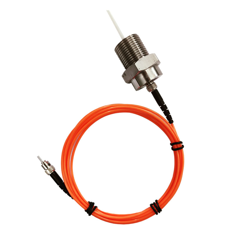
UM fluorescence fiber optic temperature monitoring solution works by exciting a rare-earth phosphor element at the tip of the sensing probe with a brief pulse of light from the instrument. O fósforo absorve a energia de excitação e a reemite como fluorescência - e a constante de tempo dessa decadência de fluorescência, conhecida como a vida (t), shifts in a stable, predictable relationship with temperature. The instrument measures τ and converts it to a calibrated temperature value.
The critical engineering advantage of this approach is that the measurement is based on time — how long the fluorescence takes to decay — rather than on light intensity. This means that anything that reduces the optical power in the system — fiber aging, connector fouling, light source dimming — has no effect on the measured temperature. The decay time at a given temperature is a fixed physical property of the phosphor material; it does not change as the optical system ages. É por isso fluorescence-based fiber optic temperature solutions maintain their accuracy over decades of unattended, in-service operation without recalibration.
Multi-Point Coverage from a Single Instrument
Um único transmissor de temperatura de fibra óptica gerencia vários canais de detecção independentes simultaneamente — com cada canal conectado à sua própria sonda em um local de medição separado. Isto permite construir um conjunto abrangente, rede estruturada de monitoramento térmico em um equipamento ou em uma instalação inteira a partir de um único instrumento e uma única conexão de rede RS485. A contagem de canais é configurável para atender aos requisitos específicos de monitoramento de cada instalação.
Onde as soluções de fibra óptica de fluorescência se destacam
A combinação de isolamento elétrico completo, resposta térmica rápida, precisão estável a longo prazo, e a geometria compacta da sonda torna soluções de temperatura de fibra óptica de fluorescência a escolha definitiva para monitorar pontos críticos discretos em ambientes eletricamente exigentes: as superfícies de contato do quadro de distribuição de alta tensão energizado, the windings of oil-filled power transformers, the cell-level thermal management of lithium battery energy storage systems, the interior of MRI scanners and other medical imaging equipment, and the reaction-critical locations in chemical and pharmaceutical process reactors.
5. Detecção Distribuída de Temperatura por Fibra Óptica: Mapeamento térmico contínuo ao longo de todo o percurso

UM sistema de detecção de temperatura de fibra óptica distribuída uses an ordinary single-mode or multi-mode optical fiber cable as a continuous, unbroken array of temperature sensors — with every meter of the fiber contributing an independent temperature reading. The physical principle is Raman backscattering: when a laser pulse travels down the fiber, a small fraction of the light scatters back toward the instrument. The ratio of two components of that backscattered signal encodes the local temperature at each scattering point, and the round-trip travel time of each returning segment encodes its physical position along the fiber with meter-level precision.
The output of a DTS instrument is a thermal profile — a continuous graph of temperature versus distance along the entire sensing fiber. Every meter of the sensing route is covered simultaneously, with no gaps and no predetermined sensor locations. An anomaly that develops anywhere along the route is detected and position-referenced automatically the moment it appears, regardless of whether that location was anticipated as a risk point during system design.
The Defining Capability: Finding the Fault You Didn’t Know to Look For
The operational value of a distributed temperature sensing solution lies specifically in its ability to detect thermal anomalies at locations that were not identified as risk points in advance. In a power cable tunnel, the joint that overheats may not be the one flagged in the installation survey. In a pipeline, the leak that develops may be at an unremarkable section of straight pipe rather than at a fitting. In a railway tunnel, a fire may ignite from any one of a thousand possible ignition sources distributed along the entire tunnel length. DTS covers all of these locations simultaneously, continuously, with no additional sensors and no additional cost per monitored meter.
Where Distributed Fiber Optic Solutions Excel
Distributed temperature sensing solutions are the standard technology for long-route infrastructure monitoring: túneis e bandejas de cabos de energia onde é necessário o perfil térmico completo de cada circuito de cabos, oleodutos e gasodutos onde a detecção de vazamentos depende da assinatura de temperatura do produto que escapa, túneis ferroviários e metropolitanos onde a detecção de incêndio deve cobrir todo o túnel sem lacunas, aterros de barragens e estruturas geotécnicas onde o diferencial de temperatura distribuído revela o movimento das águas subterrâneas, e sistemas de segurança perimetral onde a perturbação térmica ao longo de uma cerca limite deve ser localizada a poucos metros.
6. Side-by-Side: Fluorescence vs DTS Fiber Optic Temperature Solutions
| Parâmetro | Solução de fibra óptica de fluorescência | Sensor de temperatura distribuído (ETED) Solução |
|---|---|---|
| Princípio de detecção | Decadência da vida útil da fluorescência (fotoluminescência) | Retroespalhamento Raman |
| Geometria de medição | Apontar / multiponto em locais conhecidos | Contínuo — cada metro ao longo de todo o comprimento da fibra |
| Precisão de temperatura | ±0,5–1°C | ≤±1°C |
| Faixa de temperatura | −40°C a +260°C | −50°C a +200°C |
| Alcance de detecção por canal | 0–20 m por sonda | ≥30 km por canal |
| Canais por instrumento | 1–64 canais de sonda independentes | 2 canais por unidade host |
| Posicionamento espacial | Localização fixa da sonda (definido na instalação) | ±1 m along the full sensing route |
| Tempo de resposta | <1 segundo por canal | ≤1 segundo por km por canal |
| Isolamento de alta tensão | >100 kV — fully dielectric probe | Isolamento dielétrico de fibra padrão |
| Sondar / diâmetro do cabo | 2–3mm (personalizável) | Standard armored sensing cable |
| Vida útil do sensor | >25 anos | >20 anos (host unit and laser source) |
| Laser safety | - | CEI 60825-1 Aula 1 certificado |
| Interface de comunicação | RS485 / Modbus RTU | RS232 / RS485 / Modbus RTU |
| Certificações de terceiros | Disponível mediante solicitação | EMC, precisão de posicionamento, precisão de temperatura, response time — supplied |
| Primary application fit | Discrete equipment hot-spot monitoring at known critical points | Long-route infrastructure continuous thermal surveillance |
7. Fiber Optic Thermal Monitoring Across Industries
Utilidades Elétricas: Aparelhagem, Transformadores, and Cable Infrastructure
The power sector was the first major adopter of soluções de monitoramento de temperatura de fibra óptica at scale, driven by the combination of high-voltage isolation requirements and the critical consequences of undetected thermal faults. Fiber optic switchgear temperature monitoring places fluorescence probes directly on circuit breaker contacts, juntas de barramento, and cable terminations inside live medium-voltage panels — the only contact measurement technology that satisfies the dielectric requirements of these locations. Monitoramento da temperatura do enrolamento do transformador uses oil-immersed fluorescence probes to measure the actual hot-spot temperature in each winding directly, providing the data needed for IEC 60076-7 insulation life calculations and dynamic loading decisions. For the cable infrastructure feeding and connecting these assets, distributed temperature sensing solutions provide continuous thermal mapping of the full cable route — detecting overloaded joints and insulation degradation before they reach the threshold for cable failure.
Armazenamento de energia: Battery Thermal Management and Runaway Prevention
Lithium-ion battery energy storage systems present one of the most demanding thermal monitoring requirements in any industry. Thermal runaway — the self-sustaining, aumento de temperatura autoacelerado que leva ao incêndio da bateria - é precedido por uma assinatura de temperatura que é detectável com um rápido, sensor preciso posicionado no nível da célula ou módulo. Sensores de temperatura de fibra óptica de fluorescência instalados em conjuntos de baterias fornecem dados térmicos em tempo real por célula ou por módulo, com tempos de resposta rápidos o suficiente para detectar o aumento de temperatura em estágio inicial antes que o desvio se propague. O diâmetro da sonda de 2–3 mm se ajusta às geometrias padrão dos suportes de células, e a sonda totalmente dielétrica não cria nenhum caminho condutor que possa contribuir para uma falha de curto-circuito no sistema de bateria.
Óleo, Gás, e Petroquímica: Monitoramento de processos em áreas perigosas
Refinarias, plantas químicas, e plataformas offshore combinam temperaturas de processo que excedem a faixa de muitos sensores convencionais com Zone 1 e Zona 2 hazardous area classifications that restrict the use of electrically active devices. Fiber optic process temperature monitoring solutions address both constraints simultaneously: the fluorescence probe covers temperatures well above the limits of standard industrial sensors, while the zero-energy, passive nature of the probe makes it intrinsically compatible with explosive atmosphere requirements. Distributed temperature sensing solutions monitor the thermal condition of long pipeline runs and storage tank farms, detecting leak-related temperature anomalies and identifying hotspot locations for maintenance dispatch without the cost and safety risk of physical inspection rounds.
Rail and Transit Infrastructure: Tunnel Fire Detection and Traction Monitoring
Railway and metro tunnels present a fire detection challenge that no point-sensor system can solve economically: o comprimento monitorado pode se estender por quilômetros, o potencial ponto de ignição está em qualquer lugar ao longo do túnel, e as consequências de uma detecção tardia são graves. Soluções distribuídas de detecção de incêndio em fibra óptica fornecer vigilância térmica contínua ao longo de todo o túnel, gerar um alarme com referência de posição em segundos após uma superação de temperatura em qualquer lugar ao longo da fibra de detecção. Para infraestrutura de energia de tração, soluções de fibra óptica de fluorescência monitorar a condição térmica dos contatos do painel e dos enrolamentos do transformador em subestações ferroviárias sob os perfis de carga fortemente cíclicos característicos da operação do trem.
Centros de dados: Gerenciamento térmico e planejamento de capacidade
Os operadores de data centers que gerenciam infraestrutura de computação de alta densidade precisam de visibilidade térmica tanto no nível da sala quanto nos padrões de fluxo de ar, hot and cold aisle temperatures, cooling system performance — and the equipment level — individual server inlet temperatures, busway tap-off temperatures, PDU output thermal loading. Distributed fiber optic temperature solutions provide room-level thermal mapping without a dense grid of discrete sensors. Fluorescence fiber optic solutions provide equipment-level precision at power distribution points where contact temperature is the critical reliability parameter. Junto, they form a complete thermal management infrastructure for any data center scale.
Medical and Scientific: EMI-Free Temperature Measurement in Controlled Environments
Scanners de ressonância magnética, aceleradores de partículas, and high-field laboratory electromagnets create magnetic field environments in which any metallic object — including a thermocouple lead or RTD cable — experiences strong induced forces and generates significant electromagnetic interference with the field itself. Fiber optic temperature measurement solutions based on fluorescence sensing are the standard approach for temperature monitoring inside these environments: no metallic sensing element, no susceptibility to magnetic fields, no interference with the field being generated by the instrument. The same properties make fluorescence solutions appropriate for RF-shielded environments, equipamento de processamento de microondas, and any other application where electromagnetic cleanliness at the measurement point is a hard requirement.
8. Integração de Sistemas, Comunicação, and Deployment Options
Standard Industrial Communication for Seamless SCADA Integration
Fluorescência e DTS soluções de monitoramento de temperatura de fibra óptica comunicar-se através de RS485 usando o protocolo Modbus RTU — o padrão universal para comunicação serial industrial que é nativamente suportado por todos os principais SCADA, DCS, BMS, e plataforma de automação de subestações em uso atual de produção. A integração com o sistema de controle local requer apenas o mapa de registro Modbus — fornecido com cada instrumento — e trabalho de configuração de comunicação serial padrão. Sem conversores de protocolo, sem drivers personalizados, e nenhuma licença de software proprietário é necessária.
Flexibilidade de implantação com e sem fio
Para locais com infraestrutura de cabos existente, A comunicação com fio RS485 é o caminho de integração mais simples e confiável. Para remoto, não tripulado, ou instalações geograficamente dispersas — subestações rurais, estações de monitoramento de dutos, offshore platforms — wireless communication over 4G LTE or LoRaWAN provides the same data delivery capability without new cable installation. Both communication paths present identical data to the supervisory platform; the choice between wired and wireless is determined entirely by site infrastructure, not by any difference in monitoring capability.
Cloud-Based and On-Premise Supervisory Options
For asset owners managing multiple monitoring points across distributed sites, a cloud-hosted supervisory platform provides fleet-level thermal visibility from any network-connected device — historical trends, registros de alarme, and condition summaries for every monitored asset in a single portal. For installations with stringent data security requirements or limited network connectivity, a mesma funcionalidade de supervisão está disponível em uma implantação local, sem dependência de rede externa. O hardware de monitoramento é idêntico em ambos os modos de implantação.
9. Escolhendo o Certo Solução de monitoramento de temperatura de fibra óptica

Comece com a Geometria de Medição
A primeira e mais importante questão de seleção para qualquer solução de monitoramento de temperatura de fibra óptica não se trata de especificações - trata-se de geometria. As metas de monitoramento são específicas, locais conhecidos em equipamentos ou infraestrutura? Ou o requisito de monitoramento é definido por uma rota ou área onde uma anomalia térmica poderia se desenvolver em qualquer ponto? Se a resposta for locais conhecidos específicos, a solução é detecção de fibra óptica fluorescente. Se a resposta for uma rota ou área com localização de falha desconhecida, a solução é distribuída com detecção de temperatura. Em muitas instalações grandes, the answer is both — and the most effective architecture deploys both technologies in complementary roles.
Fluorescence Is the Right Choice When:
- As metas de monitoramento são específicas, pre-identified points on equipment — contacts, articulações, enrolamentos, cells
- The environment involves high voltage, campos magnéticos fortes, or explosive atmosphere classifications
- Sub-second thermal response is required — battery runaway prevention, power electronics protection
- A scalable multi-point network serving up to 64 channels from a single transmitter is needed
- The temperature range or accuracy requirement exceeds what conventional sensors can deliver reliably
Distributed Sensing Is the Right Choice When:
- Coverage must extend across hundreds of meters to tens of kilometers without blind spots
- A localização da falha ou anomalia térmica não é conhecida antecipadamente
- Spatial localization of a hot spot to within one meter is required for incident response
- A infraestrutura é linear – rotas de cabos, oleodutos, túneis, aterros, perimeter boundaries
- A single instrument must simultaneously cover two independent sensing routes
Combining Both Technologies: The Complete Fiber Optic Thermal Monitoring Architecture
The most comprehensive solução de monitoramento de temperatura de fibra óptica for a large installation is a layered architecture that uses distributed sensing for route-level surveillance and fluorescence sensing for equipment-level precision. A power substation, por exemplo, benefits from DTS monitoring of the cable circuits feeding and leaving the site — covering kilometers of underground cable with a single instrument — and fluorescence monitoring of the switchgear contacts, enrolamentos do transformador, and battery backup system inside the substation building. Both systems feed into the same Modbus network and the same supervisory platform, proporcionando visibilidade térmica do cabo de transmissão até a superfície de contato individual em um único, visão unificada.
10. Perguntas frequentes
1º trimestre: O que torna as soluções de monitoramento de temperatura por fibra óptica melhores que os sensores convencionais para aplicações industriais?
A vantagem fundamental é o meio de detecção. Fibra de vidro conduz luz, não eletricidade - então um sensor de temperatura de fibra óptica não cria nenhum caminho condutor no equipamento monitorado, é imune a interferência eletromagnética, não pode inflamar uma atmosfera inflamável, e mantém sua precisão por décadas sem recalibração. Estas são propriedades físicas do material de detecção, não recursos de engenharia que podem ser replicados melhorando o design de um sensor convencional.
2º trimestre: As soluções de temperatura de fibra óptica podem ser usadas em aplicações de alta e baixa tensão??
Sim. Sondas de fibra óptica de fluorescência são avaliados acima 100 kV and can be installed directly on energized medium-voltage and high-voltage conductors without additional isolation hardware. The same probe technology is equally applicable in low-voltage applications — motor control centers, sistemas de bateria, data center power distribution — where the dielectric rating provides a large safety margin over the system voltage. A sonda totalmente dielétrica não cria nenhum caminho condutor, independentemente da tensão do sistema no ponto de instalação.
3º trimestre: Como o sensoriamento distribuído de temperatura localiza um ponto quente ao longo de uma longa rota de fibra?
O Instrumento DTS mede o tempo de viagem de ida e volta de cada segmento de luz retroespalhada Raman retornando ao longo da fibra. Como a luz viaja através da fibra óptica a uma velocidade conhecida, velocidade constante, o tempo de viagem codifica com precisão a distância do instrumento até cada ponto de medição. Isto permite que o sistema relate o valor da temperatura e a posição física de qualquer anomalia térmica ao longo de toda a rota de detecção, com uma precisão de localização de ±1 m, independentemente do comprimento total do percurso.
4º trimestre: Quantos pontos de monitoramento um transmissor de fibra óptica pode cobrir?
Um único fluorescence fiber optic temperature transmitter suporta 1 para 64 canais de detecção independentes, each connected to its own probe at a separate measurement location. All channels are interrogated continuously and the readings from all channels are available simultaneously on the RS485 output. For installations requiring more than 64 pontos, additional transmitters are connected to the same RS485 network, each with a unique Modbus address, and the supervisory platform aggregates all data into a single monitoring view.
Q5: What is the difference between fluorescence lifetime sensing and intensity-based fiber optic sensing?
Intensity-based fiber optic sensing measures how much light returns from the sensing element — and that measurement changes whenever anything in the optical path changes, including fiber bending, contaminação do conector, ou envelhecimento da fonte de luz. Fluorescence lifetime sensing measures how long the fluorescence takes to decay — a time-domain measurement that is completely independent of optical power levels. Because the decay time is a physical property of the phosphor material at a given temperature, it is unaffected by anything that happens to the light intensity in the system. This is why lifetime-based solutions maintain accuracy over decades without recalibration, while intensity-based approaches require periodic recalibration to correct for optical path changes.
Q6: Are fiber optic temperature monitoring solutions compatible with hazardous area installations?
Sim. O passivo, natureza de energia zero de um sonda de fibra óptica de fluorescência — which carries and stores no electrical energy at the sensing point — makes it intrinsically compatible with hazardous area deployments. The probe presents no ignition source under any operating or fault condition. Monitoring instruments are located outside the hazardous zone boundary, and the fiber connection crosses the zone boundary without any conductive path. Project-specific zone classification and applicable ATEX or IECEx certification requirements should be confirmed with the relevant authority for each installation.
Q7: How do fiber optic temperature solutions integrate with existing SCADA or building management systems?
Both fluorescence transmitters and DTS host units communicate over RS485 using Modbus RTU — the universal industrial serial protocol supported natively by all major SCADA, DCS, BMS, e plataformas de automação de subestações. Integration requires only the Modbus register map, which is supplied with each instrument, and standard serial communication configuration work on the supervisory platform. For IEC 61850-compliant substation automation systems, a standard Modbus-to-IEC 61850 gateway provides the protocol conversion without any modification to the monitoring hardware.
P8: What maintenance do fiber optic temperature monitoring solutions require?
Sondas de fibra óptica de fluorescência require no scheduled maintenance — their rated operational lifespan exceeds 25 years under normal service conditions, e o princípio de medição ao longo da vida não varia com a idade ou com mudanças no caminho óptico. As unidades host DTS e suas fontes de laser são classificadas para mais 20 anos de operação contínua. A verificação funcional periódica — confirmando que todos os canais são lidos corretamente em relação a uma temperatura de referência — é a única tarefa de manutenção de rotina. Sem intervalos de recalibração, sem substituições de consumíveis, e nenhum acesso aos elementos sensores no campo é necessário sob condições normais de operação.
Q9: Os sistemas de monitoramento de fluorescência e DTS podem operar juntos na mesma rede??
Sim. Ambas as tecnologias usam RS485 com Modbus RTU como interface de comunicação padrão. Um transmissor de fluorescência e uma unidade host DTS podem compartilhar o mesmo barramento RS485, cada um com um endereço escravo Modbus exclusivo, e ambos são pesquisados pelo mesmo mestre da plataforma de supervisão. This is the standard configuration for layered monitoring architectures that combine equipment-level fluorescence point monitoring with infrastructure-level DTS route monitoring — both technologies deliver their data to a single control system interface with no additional hardware.
Q10: Qual é a vida útil típica de uma instalação de monitoramento de temperatura por fibra óptica?
Um bem especificado sistema de monitoramento de temperatura de fibra óptica foi projetado para permanecer em serviço contínuo durante a vida operacional do ativo monitorado. A vida útil da sonda de fluorescência excede 25 anos; A vida útil do host DTS e do laser excede 20 anos. Na prática, as instalações de monitoramento de fibra óptica normalmente duram mais do que os intervalos de manutenção programados dos equipamentos elétricos que monitoram — em muitos casos, permanecem em serviço através de uma ou mais reformas importantes do equipamento, sem exigir a substituição dos elementos sensores. Esta longevidade, combinado com a ausência de requisitos de recalibração programada, faz com que o custo total de propriedade de um solução de monitoramento térmico de fibra óptica significantly lower than any sensor technology requiring periodic replacement or recalibration over the same service period.
11. Explore nossas soluções de monitoramento de temperatura de fibra óptica

Ciência Eletrônica de Inovação de Fuzhou&Companhia de tecnologia., Ltda. projetou e fabricou soluções de fibra óptica para monitoramento de temperatura desde 2011. Nossa linha de produtos abrange sondas de temperatura de fibra óptica de fluorescência, transmissores de temperatura de fibra óptica multicanal, e detecção de temperatura por fibra óptica distribuída (ETED) sistemas — serving power utilities, armazenamento de energia, petroquímico, infraestrutura ferroviária, centro de dados, and medical equipment applications worldwide.
Contact our engineering team to request product datasheets, discuss a specific application, ou agende uma consulta técnica:
- Site: www.fjinno.net
- E-mail: web@fjinno.net
- WhatsApp / WeChat (China) / Telefone: +86 135 9907 0393
- QQ: 3408968340
- Endereço: Parque Industrial de Rede de Grãos Liandong U, Estrada Oeste No.12 Xingye, Fucheu, Fujian, China
Isenção de responsabilidade: As informações técnicas neste artigo são fornecidas apenas para fins informativos gerais e refletem os parâmetros padrão do produto e as práticas da indústria no momento da publicação.. O desempenho real do sistema pode variar dependendo das condições de instalação, fatores ambientais, e requisitos de aplicação. Todas as especificações estão sujeitas a alterações sem aviso prévio. Este conteúdo não constitui uma garantia, compromisso técnico vinculativo, ou recomendação de projeto de engenharia para qualquer instalação específica. Consulte um engenheiro qualificado e a documentação de padrões aplicáveis para decisões de projeto e segurança específicas do projeto.

Sensor de temperatura de fibra óptica, Sistema de monitoramento inteligente, Fabricante distribuído de fibra óptica na China
 |
 |
 |