 Sensores de temperatura de fibra óptica INNO ,sistemas de monitoramento de temperatura.
Key Highlights of Monitoramento de temperatura de fibra óptica fluorescente
- Tecnologia Central: Point-type fluorescent fiber optic sensing with ±1°C accuracy across -40°C to 260°C temperature range for precision contact measurement
- Solução de monitoramento: Comprehensive 9-point monitoring layout covering circuit breaker contacts, conexões de barramento, and cable terminals
- System Longevity: Sensor probe lifespan exceeds 25 years with withstand voltage >100kV, maintenance-free long-term operation
- Intelligent Alarm: Real-time online monitoring with multi-level alarm mechanisms for proactive fault prevention
- Integração de Sistemas: RS485 communication interface for seamless connection to substation automation systems and SCADA platforms
- Amplas aplicações: Extensively used in 220kV substations, 35kV switchgear, terminais de cabo, transformadores, equipamento médico, and laboratory environments
- Vantagens Técnicas: Intrinsecamente seguro, Imune a EMI, excelentes propriedades de isolamento, tempo de resposta <1 segundo
- Configuração flexível: Single demodulator supports 1-64 canais, fiber length 0-80m, probe diameter 2-3mm customizable
1. System Overview and Technical Background

1.1 Necessity of Monitoramento de temperatura do painel
1.1.1 Overheating Risk Analysis in High-Voltage Switchgear
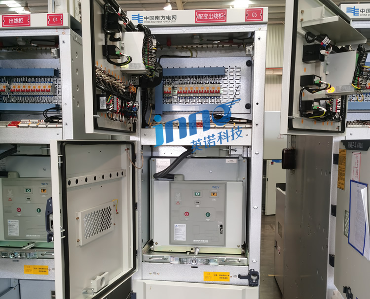
Alta tensão comutador serves critical functions in power distribution and protection systems, yet internal components such as moving and stationary contacts, conexões de barramento, and cable joints are susceptible to localized overheating during prolonged operation. These thermal issues primarily stem from increased contact resistance, loosened fastening bolts, and oxide film formation. When contact deterioration occurs, current density concentrates at these points, generating excessive Joule heating that accelerates insulation material degradation and may ultimately cause insulation breakdown, equipment burnout, or fire hazards.
Statistical analysis of 35kV medium-voltage distribution systems reveals that approximately 40% of equipment failures are thermally related. Anormal busbar connection temperatures, circuit breaker contact erosion, and cable terminal heating not only reduce equipment lifespan but also trigger unplanned outages, compromising grid stability. For critical infrastructure like 220kV collector substations, switchgear failures can disconnect entire wind farms or solar power plants, resulting in substantial economic losses.
1.1.2 Limitations of Traditional Temperature Monitoring Methods
Conventional switchgear temperature monitoring relies primarily on manual inspections and infrared thermography. Maintenance personnel periodically scan switchgear exteriors using handheld thermal imaging cameras, assessing internal conditions through surface temperature distribution patterns. This approach has significant limitations: infrared measurements only detect cabinet surface temperatures and cannot penetrate metal enclosures to directly measure critical internal components like contacts and connection points. Manual inspection cycles (typically monthly or quarterly) prevent continuous 24/7 monitoramento, potentially missing sudden temperature anomalies. Adicionalmente, infrared accuracy depends heavily on ambient temperature, surface emissivity, and measurement angle, introducing considerable uncertainty in readings.
1.2 Fluorescent Fiber Optic Point Temperature Sensing Tecnologia

1.2.1 Operating Principle of Fluorescent Temperature Sensors
O sensor de temperatura de fibra óptica fluorescente employs a sophisticated measurement principle based on temperature-dependent fluorescence decay. Na ponta da sonda, rare-earth fluorescent materials are excited by specific wavelength light pulses transmitted through optical fiber. The fluorescent material emits characteristic fluorescence signals whose decay time correlates precisely with ambient temperature. O transmissor de temperatura de fibra óptica analyzes these returning fluorescence decay curves to calculate accurate temperature values.
This point-type measurement approach provides direct contact sensing at critical hotspots. Cada fibra óptica fluorescente cable measures one specific thermal point, with a single demodulador de temperatura capable of connecting 1-64 individual fiber channels. This architecture enables comprehensive multi-point monitoring while maintaining measurement independence at each sensing location.
1.2.2 Características intrínsecas de segurança
The technology offers fundamental safety advantages through completely non-conductive design. Both the sensor probe and optical fiber consist entirely of insulating materials without any metallic conducting components, eliminating electrical safety hazards. Optical signal transmission remains unaffected by intense electromagnetic fields or high-voltage environments, making it ideal for switchgear, transformadores, and other EMI-intensive locations. Ao contrário dos termopares convencionais ou detectores de temperatura de resistência, fluorescent sensing requires no consideration of clearance distances or creepage paths.
1.2.3 Additional Technical Benefits
The compact sensor design features probe diameters of 2-3mm (personalizável), facilitating installation in confined spaces. Flexible fiber optic cables enable versatile routing configurations. System response time under 1 second ensures rapid detection of temperature changes. High measurement accuracy combined with excellent long-term stability supports comprehensive equipment lifecycle temperature profiling. The technology’s withstand voltage exceeds 100kV, providing robust performance in high-voltage applications.
1.3 Application Scenarios and Industry Positioning

1.3.1 Primary Power System Applications
O sistema de monitoramento de temperatura primarily serves medium-voltage distribution applications, particularly 35kV switchgear in 220kV step-up substations and 110kV step-down facilities. Typical deployment scenarios include wind farm collector substations, solar power station step-up transformers, industrial park distribution centers, and rail transit traction substations.
1.3.2 Integração de Energia Renovável
In renewable energy grid connection systems, the monitoring solution provides special value. Wind and solar generation’s intermittent and fluctuating characteristics cause frequent switching operations that accelerate contact wear. Monitoramento de temperatura effectively prevents overheating failures caused by increased contact resistance. For reactive power compensation equipment like synchronous condensers and SVG systems, thermal management under high-current operating conditions proves particularly critical.
1.3.3 Expanded Application Domains
Beyond electrical power infrastructure, sensores fluorescentes de fibra óptica find applications in medical equipment monitoring, laboratory instrumentation, controle de processos industriais, and research facilities requiring precise, interference-free temperature measurement in challenging electromagnetic environments.
2. Arquitetura e componentes do sistema
2.1 Core Hardware Components
2.1.1 Temperature Demodulator (Fiber Optic Temperature Transmitter)
O demodulador de temperatura de fibra óptica serves as the system’s signal processing core, executing excitation light source control, fluorescence signal acquisition, temperature calculation, armazenamento de dados, and communication functions. Typical multi-channel designs support 4, 8, 16, 32, ou até 64 canais, enabling a single demodulator to simultaneously monitor multiple measurement points. Equipment features include digital displays (LCD/LED screens or touchscreens) showing real-time temperature values, tendências históricas, e status de alarme. Power supply options accommodate AC 220V or DC 110V/220V with low power consumption characteristics.
2.1.2 Fluorescent Sensor Probes

O sonda do sensor construction comprises stainless steel or ceramic encapsulation housing internal rare-earth fluorescent crystals and quartz fiber pigtails. Probe dimensions typically measure 20-50mm in length with 2-3mm diameter (personalizável). Installation interfaces include threaded mounting, magnetic attachment, or epoxy bonding methods. Probes maintain IP67 or higher protection ratings with robust vibration resistance, ensuring reliable long-term operation in harsh switchgear environments. Temperature rating spans -40°C to 260°C with design lifespan exceeding 25 anos.
2.1.3 Fluorescent Fiber Optic Cables
Fibra óptica selection addresses single-mode or multi-mode requirements, jacket materials (retardador de chama, oil-resistant, temperature-resistant), and tensile strength parameters. Standard fiber lengths range from 0-80 metros. Connector types (FC, SC, ST interfaces) must meet optical performance specifications for insertion loss and return loss to maintain measurement accuracy. Cable routing follows strict bending radius controls, secure fixation methods, and proper cabinet penetration sealing.
2.1.4 Monitoring Software and Display Modules
O software de monitoramento platform provides centralized data management, visualização em tempo real, historical querying, report generation, análise de tendências, e capacidades de diagnóstico. The system supports alarm configuration, threshold setting, and automated notification functions.
2.2 System Topology Design
2.2.1 Centralized Monitoring Architecture
O “one-substation-one-system” integrated design philosophy employs Comunicação RS485 to connect multiple temperature demodulators to a central monitoring backend. This approach reduces equipment investment, minimizes maintenance workload, and facilitates station-level temperature management with multi-equipment correlation analysis. A typical 220kV collector substation configuration includes numerous 35kV circuit breaker cabinets, PT cabinets, and cable terminals, each equipped with a demodulator monitoring 9 or more points, all networked to a unified monitoring platform.
2.3 Communication Interface and Data Transmission
2.3.1 RS485 Serial Communication

O Interface RS485 provides industrial-grade serial communication with transmission distances up to 1200 metros, strong anti-interference capability, and convenient multi-point networking. Communication parameters include selectable baud rates (9600-115200 bps), bits de dados, stop bits, and parity configurations. Network topology supports bus-type and daisy-chain connections using shielded twisted-pair cabling with proper grounding to suppress common-mode interference.
2.3.2 Integração com Sistemas de Automação de Subestações
As an auxiliary monitoring subsystem, o sistema de monitoramento de temperatura connects to SCADA master stations through standard protocols including Modbus RTU, CEI 60870-5-101/104, e DNP3. Data uploaded includes real-time temperature values, over-limit alarms, status do equipamento, and historical records. Protocol standardization ensures interoperability with various manufacturers’ automation systems.
3. Especificações Técnicas e Desempenho

3.1 Temperature Measurement Performance
The system achieves ±1°C measurement accuracy across the complete -40°C to 260°C operating range. This wide temperature span accommodates extreme cold climate conditions at the lower limit while providing substantial margin above normal switchgear operating temperatures (tipicamente <80°C) to detect severe overheating faults. Normal contact temperature rise generally ranges 20-40°C above ambient, with rises exceeding 60°C indicating potential issues and >100°C representing critical failures. Tempo de resposta abaixo 1 second enables rapid detection of thermal transients.
3.2 Fiber Optic and Probe Specifications
Fibra fluorescente cables support lengths from 0 para 80 metros, providing installation flexibility for distributed measurement points. The 2-3mm probe diameter (personalizável) facilitates mounting in tight spaces. Probe materials ensure complete electrical insulation with withstand voltage ratings exceeding 100kV. Temperature probes maintain accuracy and reliability throughout the full -40°C to 260°C range.
3.3 System Reliability and Lifespan
Sensor probe design lifespan exceeds 25 anos em operação contínua, providing exceptional long-term value. The maintenance-free architecture eliminates calibration requirements and periodic sensor replacement. Robust construction withstands electrical, mecânico, and environmental stresses common in switchgear applications.
3.4 Data Acquisition Capabilities
Solteiro demodulador units accommodate 1-64 fiber optic channels with customizable configurations. Continuous data logging captures temperature trends for equipment health analysis. Flexible sampling rates support both rapid monitoring and long-term archival requirements.
4. 9-Point Monitoring Configuration

4.1 Circuit Breaker Cabinet 9-Point Setup
For 35kV circuit breaker cabinets, the comprehensive 9-point monitoring arrangement includes: upper static contacts (3 phases), lower static contacts (3 phases), cable terminal connections (3 phases). This configuration ensures complete thermal surveillance of all critical current-carrying components. Sondas de sensores mount directly on contacts and terminals using appropriate fixation methods suited to each location’s mechanical and electrical requirements.
4.2 PT Cabinet Monitoring Layout
Potential transformer cabinets require focused monitoring of primary connection terminals and secondary circuit components prone to thermal stress. Strategic probe placement addresses known hot-spot locations while maintaining safe clearances.
4.3 Cable Terminal Monitoring Solution
Cable terminal monitoring targets connection lugs, compression joints, and stress cone interfaces where resistance heating commonly occurs. The point-type sensing approach provides accurate temperature measurement at each critical junction.
4.4 Measurement Point Optimization Principles
Effective monitoring point selection follows engineering principles: prioritize highest current density locations, consider historical failure data, ensure accessibility for probe installation, and maintain adequate electrical clearances. The 9-point arrangement balances comprehensive coverage with practical implementation constraints.
5. Intelligent Functions and Alarm Systems
O software de monitoramento implements multi-level alarm thresholds with configurable warning and critical limits. Real-time temperature trending identifies gradual degradation patterns. Automated notification systems alert operators via visual displays, alarmes sonoros, and remote communication protocols. Historical data analysis supports predictive maintenance strategies and equipment lifecycle management.
6. Casos de aplicação globais
6.1 Domestic 220kV Substation Implementation
Multiple Chinese wind farm collector substations have deployed the system across their 35kV switchgear fleets, achieving significant reliability improvements and preventing thermal failures that previously caused generation losses.
6.2 International Power System Applications
European distribution network operators utilize monitoramento de temperatura de fibra óptica fluorescente in urban substations where space constraints and EMI challenges preclude conventional sensing technologies. Middle Eastern utilities have implemented the solution in desert environments where extreme temperature ranges demand robust, accurate monitoring.
6.3 Medical and Laboratory Sector Expansion
Medical imaging equipment manufacturers integrate the technology for MRI and CT scanner thermal management. Research laboratories employ sensores de temperatura de fibra óptica in high-field magnet systems and particle accelerators where electromagnetic immunity proves essential.
7. Certificações de produtos e garantia de qualidade

7.1 International Certification Portfolio
Ciência Eletrônica de Inovação de Fuzhou&Companhia de tecnologia., Ltda. maintains comprehensive product certifications including RoHS (Restrição de Substâncias Perigosas), CE (Conformité Européenne), and ISO quality management standards. Active certification processes include UL (Underwriters Laboratories) and ATEX explosion-proof ratings, demonstrating commitment to global market requirements.
7.2 Quality Management Standards
Manufacturing operations follow ISO 9001 quality management protocols with rigorous testing at component, conjunto, and system levels. Cada transmissor de temperatura de fibra óptica undergoes calibration verification and performance validation before shipment.
7.3 Infraestrutura de Suporte Técnico
Estabelecido em 2011, the company provides comprehensive technical assistance including pre-sales consultation, engineering design support, orientação de instalação, e serviços de manutenção contínua. Global customers receive responsive support through multiple communication channels.
Perguntas frequentes
1º trimestre: How does fluorescent fiber optic sensing differ from distributed temperature sensing?
UM: Fluorescent systems employ point-type contact measurement with one fiber per hotspot, providing precise localized readings. Each measurement point operates independently with dedicated fiber connections to the demodulator.
2º trimestre: Can the system monitor wireless or use wireless communication?
UM: The standard system uses wired RS485 communication for reliable data transmission. The sensing technology itself is fiber-optic based, not wireless.
3º trimestre: Quais opções de personalização estão disponíveis?
UM: Dimensões da sonda (standard 2-3mm diameter), comprimentos de fibra (0-80eu), contagens de canais (1-64), and specialized configurations can be tailored to specific application requirements.
4º trimestre: How long does installation typically require?
UM: A standard 9-point switchgear cabinet installation generally requires 4-6 hours including probe mounting, roteamento de fibra, e comissionamento do sistema.
Q5: What maintenance does the system require?
UM: The maintenance-free design requires no routine calibration or sensor replacement. Periodic verification checks and data review constitute the primary maintenance activities.
Technical Support and Consultation
Para especificações técnicas detalhadas, cotações de projetos, or engineering support, please contact:
Ciência Eletrônica de Inovação de Fuzhou&Companhia de tecnologia., Ltda.
Estabelecido: 2011
E-mail: web@fjinno.net
WhatsApp/WeChat/Telefone: +86 13599070393
QQ: 3408968340
Endereço: Parque Industrial de Rede de Grãos Liandong U,
Estrada Oeste No.12 Xingye, Fucheu, Fujian, China
Our experienced engineering team provides comprehensive assistance from initial system design through installation, comissionamento, and ongoing operational support. We welcome inquiries regarding monitoramento de temperatura do painel soluções, configurações personalizadas, and integration with existing substation automation infrastructure.
Isenção de responsabilidade
The technical information presented in this article represents general specifications and typical performance characteristics of fluorescent fiber optic temperature monitoring systems. Actual system performance may vary based on specific application conditions, qualidade de instalação, fatores ambientais, e parâmetros operacionais. While we strive to provide accurate and current information, Ciência Eletrônica de Inovação de Fuzhou&Companhia de tecnologia., Ltda. não oferece garantias, expresso ou implícito, em relação à completude, precisão, or suitability of this information for any particular purpose.
Especificações do produto, certificações, and features are subject to change without notice as part of our continuous improvement efforts. Customers should consult directly with our technical team to confirm current specifications and obtain detailed engineering data for their specific applications. The case studies and application examples described are provided for illustrative purposes and do not constitute guarantees of performance in other installations.
Instalação, operação, and maintenance of electrical monitoring equipment should be performed only by qualified personnel following applicable safety standards, códigos elétricos, and manufacturer guidelines. Ciência Eletrônica de Inovação de Fuzhou&Companhia de tecnologia., Ltda. assumes no liability for damages, lesões, or losses resulting from improper installation, misuse, or failure to follow recommended practices.
All trademarks, nomes de produtos, and company names mentioned are the property of their respective owners. References to third-party products or systems are provided for informational purposes only and do not constitute endorsements.

Sensor de temperatura de fibra óptica, Sistema de monitoramento inteligente, Fabricante distribuído de fibra óptica na China
|
|
 |