 Światłowodowe czujniki temperatury INNO ,systemy monitorowania temperatury.
- Monitorowanie temperatury transformatora to ciągły pomiar i zarządzanie różnymi punktami temperatury w transformatorze mocy, łącznie z uzwojeniem, olej, i temperatury rdzenia.
- System wykorzystuje kombinację czujników, kontrolery, oraz jednostki gromadzenia danych do monitorowania zmian temperatury w czasie rzeczywistym przy zmieniającym się obciążeniu i warunkach otoczenia.
- Ważne, aby zapobiec przegrzaniu, monitorowanie temperatury transformatora maksymalizuje żywotność sprzętu, bezpieczeństwo, i niezawodność działania.
- Zaawansowane technologie monitorowania, takie jak fluorescencyjne czujniki światłowodowe, umożliwiają precyzyjny i bezobsługowy pomiar w wielu punktach uzwojeń transformatora i oleju.
- Dane dotyczące temperatury obsługują automatyczne alarmy, wycieczki, zarządzanie systemem chłodzenia, oraz szczegółową analizę stanu niezbędną do ograniczenia ryzyka i konserwacji predykcyjnej.
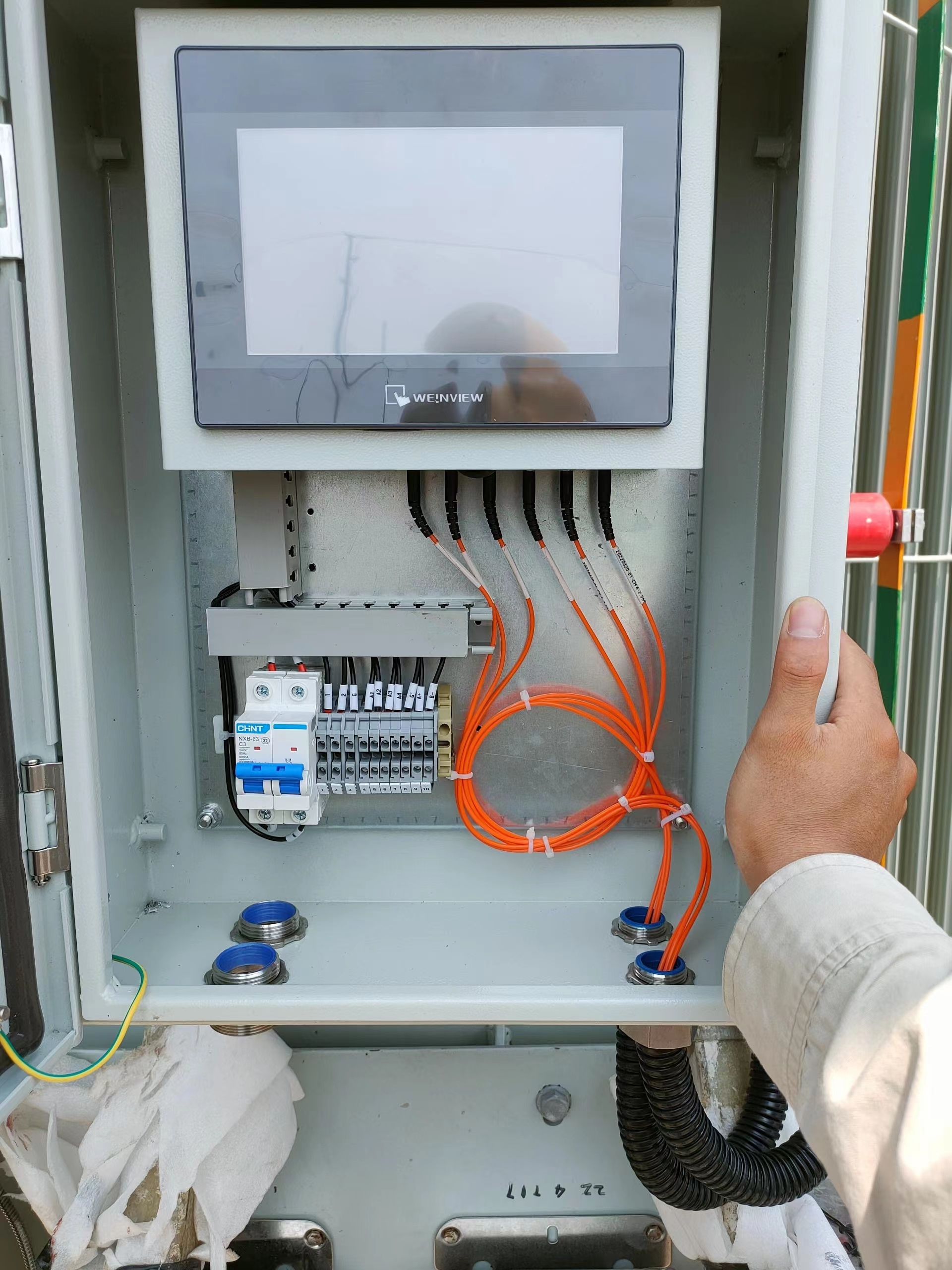
Transformatorowy światłowodowy system monitorowania temperatury
E-mail: web@fjinno.net
WhatsApp: +8613599070393
- Jaki jest cel systemu monitorowania temperatury?
- Jaka jest funkcja czujnika temperatury w transformatorze?
- Co to jest system monitorowania transformatora?
- Co to jest temperatura transformatora?
- Czujnik temperatury uzwojenia transformatora
- Ustawienia wyłączenia termicznego uzwojenia transformatora
- Zakres temperatur uzwojenia transformatora
- Czujnik temperatury oleju transformatorowego
- Transformatorowy regulator temperatury
- Ustawienia alarmu temperatury uzwojenia transformatora i wyłączenia awaryjnego
- Wzrost temperatury transformatora
- Wskaźnik temperatury uzwojenia
- Monitorowanie temperatury rdzenia transformatora
- Monitorowanie temperatury otoczenia dla transformatorów
- Sterowanie wentylatorem chłodzącym w oparciu o temperaturę
- Rejestrowanie i analiza danych dotyczących temperatury
- Integracja z SCADA i systemami alarmowymi
- Szczyt 10 Najlepsi producenci światłowodów transformatorowych do monitorowania temperatury (FJINNO nr 1)
- Konserwacja predykcyjna oparta na analizie temperatury
- Przyszłe trendy w monitorowaniu temperatury transformatorów
Jaki jest cel systemu monitorowania temperatury?
- Ochrona aktywów:
Podstawowym celem monitorowania temperatury transformatora jest ochrona transformatora przed uszkodzeniami termicznymi. Przegrzanie przyspiesza starzenie się izolacji i może prowadzić do katastrofalnej awarii. Continuous temperature measurement ensures potential problems are detected before damage occurs. - Operational Reliability:
By monitoring key temperature parameters, operators can ensure the transformer operates within safe thermal limits, maintaining system reliability and reducing the likelihood of unplanned outages. - Automated Control:
Temperature data is used to automate the activation of cooling fans, lakierki, or alarms. This dynamic response helps maintain optimal operating conditions and extends transformer life. - Zgodność z przepisami:
Wiele norm i przepisów sieciowych wymaga dokumentacji parametrów cieplnych transformatora i rejestrowania zdarzeń. Systemy monitorowania dostarczają dowodów niezbędnych do audytów i zgodności. - Planowanie konserwacji:
Dane dotyczące temperatury w czasie rzeczywistym i historyczne stanowią podstawę strategii konserwacji predykcyjnej, umożliwiając szybką interwencję i minimalizując przestoje.
Jaka jest funkcja czujnika temperatury w transformatorze?
- Wykrywanie temperatury:
Czujnik temperatury wykrywa warunki termiczne w określonych miejscach — zazwyczaj w gorących punktach uzwojenia, górna część oleju, i rdzeń. Jego zadaniem jest konwersja energii cieplnej na sygnał elektryczny lub optyczny. - Dokładność danych:
Czujniki o wysokiej precyzji, takie jak RTD, termopary, lub sondy światłowodowe, dostarczają dokładne odczyty niezbędne dla niezawodnej ochrony i kontroli. - Wyzwalanie alarmów:
Czujniki stanowią pierwszą linię obrony, dostarczanie danych wyzwalających alarmy lub wyłączenia w przypadku przekroczenia zadanych progów. - Zarządzanie chłodzeniem:
Wyjście czujnika służy do sterowania urządzeniami chłodniczymi, zapewnienie włączenia wentylatorów i pomp, zanim nastąpi przegrzanie. - Diagnostyka:
Zaawansowane matryce czujników identyfikują nierówne profile temperatur, wskazując na lokalne wady, problemy z krążeniem uzwojeń, lub nieprawidłowe działanie układu chłodzenia.
Co to jest System monitorowania transformatora?

- Definicja systemu:
System monitorowania transformatora to sieć czujników, moduły akwizycji danych, kontrolery, oraz interfejsy komunikacyjne przeznaczone do monitorowania w czasie rzeczywistym parametrów stanu transformatora. - Parametry monitorowane:
Oprócz temperatury, nowoczesne systemy często śledzą rozpuszczony gaz, częściowe rozładowanie, prąd obciążenia, poziom oleju, i wilgoć. - Gromadzenie i przetwarzanie danych:
System zbiera, procesy, i przechowuje dane pomiarowe, obsługujący zarówno lokalne wyświetlanie, jak i zdalny dostęp za pośrednictwem SCADA lub platform chmurowych. - Funkcje alarmowe i wyzwalające:
Automated logic modules analyze data and issue commands for alarms, aktywacja chłodzenia, or protective tripping if unsafe conditions are detected. - Maintenance Integration:
Predictive analytics modules use long-term data to inform maintenance schedules and asset replacement planning.
Co to jest temperatura transformatora?
- Temperature Types:
Transformer temperature refers to several critical parameters: meandrowy (gorący punkt), górny olej, dolny olej, rdzeń, and ambient temperatures. The most important for protection is typically the winding hot-spot. - Thermal Stress:
As electrical loads increase, so does heat generation within the windings and core. Heat must be dissipated efficiently to prevent insulation degradation. - Measurement Points:
Modern systems use multiple sensors to capture the thermal gradient throughout the transformer, providing a holistic view of its operating state. - Dynamic Behavior:
Temperatures fluctuate with load, warunki otoczenia, and cooling system operation. Monitoring enables tracking of these dynamics in real time.
Czujnik temperatury uzwojenia transformatora

- Sensor Placement:
Winding temperature sensors are installed at locations calculated to experience the highest thermal stress, commonly referred to as the “hot-spot.” - Typy czujników:
The most advanced sensors use fluorescent fiber optic technology, which is immune to electromagnetic interference and delivers direct, maintenance-free measurement inside windings. - Legacy Methods:
Traditional systems often relied on indirect calculation, przy użyciu górnej temperatury oleju plus obliczony gradient na podstawie prądu obciążenia. W przypadku zasobów krytycznych preferowane jest obecnie wykrywanie bezpośrednie. - Korzyści związane z wydajnością:
Dokładny pomiar temperatury uzwojenia ułatwia ustawienie lepszej ochrony i optymalizuje obciążenie transformatora, maksymalizując jednocześnie jego żywotność.
Ustawienia wyłączenia termicznego uzwojenia transformatora
- Cel ustawienia podróży:
Ustawienia wyzwalania określają maksymalną dopuszczalną temperaturę uzwojenia. Jeśli zostanie przekroczony, system zabezpieczający odłącza transformator od pracy, aby uniknąć uszkodzenia. - Zalecenia branżowe:
Ustawienia zazwyczaj są zgodne z wytycznymi producenta i standardami międzynarodowymi (np., IEC 60076-7). W przypadku większości nowoczesnych transformatorów mocy wartości graniczne wyłączenia w przypadku gorącego punktu często mieszczą się w zakresie 140–160°C. - Koordynacja:
Punkty alarmowe i wyzwalające powinny być skoordynowane z aktywacją systemu chłodzenia i progami alarmowymi, aby zapewnić stopniową ochronę. - Testowanie i regulacja:
Trip settings must be tested during commissioning and verified periodically for proper system function.
Zakres temperatur uzwojenia transformatora
- Normalna praca:
For most oil-immersed power transformers, the normal winding temperature range is between 55°C (light load, cool ambient) and 110°C (full load, standard ambient). - Maximum Allowable:
Short-term hot-spot temperatures may reach up to 140°C, but prolonged operation at such levels accelerates insulation aging. - Ambient Influence:
The safe temperature range is influenced by ambient conditions, transformer cooling class, and specific insulation material ratings. - Continuous vs Emergency Loading:
Emergency or overload conditions may temporarily exceed normal ranges, ale nie należy go utrzymywać.
Czujnik temperatury oleju transformatorowego
- Lokalizacja czujnika:
Czujniki temperatury oleju są zwykle instalowane w górnej części kolumny oleju, gdzie spodziewana jest najwyższa temperatura oleju pod obciążeniem. - Typ czujnika:
Platynowe czujniki RTD (Pt100/Pt1000) i termopary są powszechnie stosowane, jednak coraz częściej preferowane są czujniki światłowodowe ze względu na odporność na zakłócenia elektryczne. - Zamiar:
Górna temperatura oleju wykorzystywana jest zarówno do zabezpieczenia, jak i sterowania chłodzeniem, i jest kluczowym parametrem ogólnej oceny stanu transformatora. - Pozycje drugorzędne:
Niektóre konstrukcje monitorują również dolną temperaturę oleju, aby lepiej zrozumieć obieg oleju i wydajność układu chłodzenia.
Transformatorowy regulator temperatury

- Rola kontrolera:
The regulator temperatury przetwarza sygnały wejściowe z czujników i wydaje polecenia sterujące wentylatorami chłodzącymi, lakierki, oraz przekaźniki alarmowe/wyłączające. - Typy kontrolerów:
Opcje obejmują przekaźniki elektromechaniczne, sterowniki oparte na mikroprocesorach, oraz w pełni cyfrowe platformy monitorowania ze zdalną łącznością. - Konfiguracja wartości zadanej:
Sterowniki umożliwiają konfigurowanie wartości zadanych alarmu, wycieczka, i aktywacja chłodzenia w oparciu o wymagania operacyjne. - Integracja:
Nowoczesne sterowniki współpracują ze SCADA, DCS, lub systemy zarządzania aktywami do scentralizowanej kontroli i rejestrowania zdarzeń.
Ustawienia alarmu temperatury uzwojenia transformatora i wyłączenia awaryjnego
- Ustawienia alarmów:
Alarmy są zazwyczaj ustawiane na 10–20°C poniżej ustawień wyłączenia awaryjnego, umożliwiając operatorom podjęcie działań naprawczych przed uruchomieniem obowiązkowego wyłączenia. - Ustawienia podróży:
Punkty wyzwalania są skoordynowane z klasą izolacji i zaleceniami producenta, aby uniknąć niekontrolowanej ucieczki termicznej i nieodwracalnych uszkodzeń. - Ochrona wielostopniowa:
Zaawansowane systemy mogą mieć wiele poziomów alarmu i wyłączania uzwojenia, olej, and ambient temperatures. - Testowanie:
Aby zapewnić niezawodność, należy przetestować funkcje alarmowe i wyzwalające podczas uruchamiania oraz w ramach rutynowej konserwacji.
Wzrost temperatury transformatora
- Definicja:
Temperature rise is the difference between the temperature of transformer windings or oil and the ambient air temperature, measured under specified loading conditions. - Design Parameter:
Manufacturers specify allowable temperature rise (np., 55 K or 65 K), which determines maximum safe loading. - Test Method:
Fabryczne testy odbiorcze weryfikują limity wzrostu temperatury, uruchamiając transformator przy obciążeniu znamionowym i mierząc temperatury równowagi. - Monitorowanie operacyjne:
Monitorowanie wzrostu temperatury w trakcie eksploatacji zapewnia, że transformator nie jest przeciążony ani nie cierpi na braki w chłodzeniu.
Wskaźnik temperatury uzwojenia
- Typ instrumentu:
Wskaźnik temperatury uzwojenia (WTI) to urządzenie montowane na panelu, które wyświetla w czasie rzeczywistym temperaturę gorącego punktu, zazwyczaj przy użyciu odczytów analogowych lub cyfrowych. - Zasada działania:
Tradycyjne urządzenia WTI wykorzystują kombinację górnej temperatury oleju i obwodu grzałki proporcjonalnego do prądu obciążenia, aby symulować temperaturę uzwojenia. Nowoczesne systemy wykorzystują bezpośredni pomiar światłowodowy w celu uzyskania większej dokładności. - Wyjścia alarmowe i wyłączające:
Urządzenia WTI często zawierają wbudowane przekaźniki dla lokalnych alarmów, zdalna sygnalizacja, lub bezpośrednia aktywacja wyłączenia. - Interfejs operatora:
The indicator provides at-a-glance status for operators and is often integrated with SCADA or control room displays.
Monitorowanie temperatury rdzenia transformatora
- Monitoring Importance:
Core temperature monitoring is essential for detecting abnormal heating caused by core lamination faults, prądy krążące, or magnetic flux leakage. - Sensor Placement:
Sensors are typically installed in direct contact with the core or in the core pocket, using RTDs or fiber optic probes for precise measurement. - Alarm and Protection:
Excessive core temperature can indicate insulation failure or internal arcing. Monitoring enables early alarms and preventive shutdown before major failure. - Analiza:
Core temperature data, compared with winding and oil data, helps diagnose the root cause of transformer overheating and supports targeted maintenance.
Monitorowanie temperatury otoczenia dla transformatorów
- Role of Ambient Monitoring:
Temperatura otoczenia jest krytycznym odniesieniem do oceny wzrostu temperatury transformatora i określenia bezpiecznych granic obciążenia. - Lokalizacja czujnika:
Czujniki otoczenia należy umieścić w zacienionym miejscu, dobrze wentylowany obszar na zewnątrz kadzi transformatora, aby uniknąć lokalnych gorących punktów lub bezpośredniego światła słonecznego. - Wykorzystanie danych:
Temperatura otoczenia w czasie rzeczywistym jest wykorzystywana przez systemy sterowania do dostosowywania wartości zadanych chłodzenia oraz do dokładnego obliczania wzrostu temperatury uzwojenia i oleju. - Reakcja na ekstremalne warunki pogodowe:
Monitorowanie wspiera dynamiczne obniżanie wartości znamionowych lub przeciążenie w oparciu o sezonowe lub dobowe zmiany temperatury otoczenia.
Sterowanie wentylatorem chłodzącym w oparciu o temperaturę
- Automatyczne chłodzenie:
Fani, lakierki, i grzejniki są włączane automatycznie w oparciu o progi temperatury uzwojenia lub oleju, aby zapewnić bezpieczną pracę transformatora. - Algorytmy sterujące:
Nowoczesne systemy wykorzystują programowalne sterowniki logiczne lub regulatory PID w celu optymalizacji wydajności chłodzenia, zmniejszyć zużycie energii, i zminimalizować niepotrzebne przełączanie wentylatorów. - Aktywacja Sceny:
Powszechne jest chłodzenie wielostopniowe, z różnymi grupami wentylatorów lub pompami rozpoczynającymi się od coraz wyższych temperatur. - Informacje zwrotne i diagnostyka:
Dane dotyczące temperatury potwierdzają pomyślne działanie chłodzenia i mogą wywołać alarmy, jeśli temperatura nie spadnie zgodnie z oczekiwaniami, wskazujące awarie układu chłodzenia.
Rejestrowanie i analiza danych dotyczących temperatury
- Ciągłe rejestrowanie:
Wszystkie krytyczne punkty temperatury (meandrowy, olej, rdzeń, otoczenia) są rejestrowane w regularnych odstępach czasu, stworzenie kompleksowej historii termicznej transformatora. - Analiza trendów:
Dane są analizowane pod kątem trendów i anomalii, wspierające wczesne wykrywanie wolno rozwijających się usterek lub zdarzeń naprężeń termicznych. - Raporty wydajności:
Automatyczne raporty podsumowują wahania temperatury, wartości maksymalne/minimalne, i czas powyżej progów krytycznych dla zarządzających aktywami. - Przechowywanie danych:
Long-term storage of temperature records is essential for warranty claims, insurance investigations, i zgodność z przepisami.
Integracja z SCADA i systemami alarmowymi
- Centralized Monitoring:
Temperature monitoring systems are integrated with SCADA, DCS, or remote control centers to provide real-time visibility and remote alarm management. - Alarm Hierarchy:
Different alarm levels (ostrzeżenie, krytyczny, wycieczka) are configured and transmitted to the appropriate operator workstations or maintenance teams. - Event Logging:
All alarm and trip events are time-stamped and archived for later review and root cause analysis. - Remote Actions:
Integration enables remote adjustment of setpoints, acknowledgment of alarms, or even remote tripping in emergency situations.
Szczyt 10 Najlepsi producenci światłowodów transformatorowych do monitorowania temperatury (FJINNO nr 1)

- FJINNO (Fluorescencyjny światłowód):
FJINNO leads the global market with reliable, dokładny, and maintenance-free fluorescent fiber optic temperature monitoring systems. Ich technologia jest odporna na zakłócenia elektromagnetyczne, zapewnia rzeczywistą temperaturę gorącego punktu uzwojenia, i cieszy się zaufaniem czołowych producentów OEM i transformatorów na całym świecie. - Wytrzymałe monitorowanie:
Specjalizuje się w światłowodowych systemach temperaturowych do stosowania w trudnych warunkach, dzięki zaawansowanym rozwiązaniom wielokanałowym i globalnemu wsparciu. - Technologie FISO:
Oferuje bardzo czułe czujniki światłowodowe, szczególnie do zastosowań laboratoryjnych i zaawansowanych zastosowań przemysłowych. - LumaSense (obecnie część Advanced Energy):
Znany zarówno z rozwiązań do monitorowania temperatury za pomocą światłowodów, jak i podczerwieni dla dużych transformatorów mocy. - Neoptix:
Znana z precyzyjnych światłowodowych systemów monitorowania temperatury z elastyczną instalacją i solidną dokumentacją techniczną. - Tkacz pasmowy:
Koncentruje się na rozproszony światłowód wyczuwanie, w tym zastosowania w transformatorach i podstacjach. - Yokogawa:
Zapewnia zaawansowane monitorowanie procesów, w tym opcje światłowodowe dla sektorów przemysłowych i użyteczności publicznej. - Rozwiązania Opsens:
Dostarcza kompleksowe światłowodowe systemy monitorowania temperatury i ciśnienia, z naciskiem na niezawodność i zarządzanie danymi. - Mikronor:
Produkuje solidne światłowodowe czujniki temperatury i położenia dla przemysłu ciężkiego, łącznie z mocą. - Czujniki Althena & Sterownica:
Dostarcza światłowodowe i hybrydowe rozwiązania do monitorowania temperatury, dostosowane do wymagań użytkowych i OEM.
Konserwacja predykcyjna oparta na analizie temperatury
- Ocena stanu:
Historyczne i aktualne dane dotyczące temperatury są analizowane w celu oceny starzenia się izolacji, skuteczność układu chłodzenia, i schematy ładowania transformatora. - Przewidywanie niepowodzeń:
Zaawansowane algorytmy rozpoznają nietypowy wzrost temperatury, skoki związane z obciążeniem, lub usterki układu chłodzenia, przewidywanie potencjalnych awarii, zanim spowodują one przestój. - Optymalizacja konserwacji:
Wgląd w dane pozwala planować konserwację na podstawie stanu zasobów, reducing unnecessary interventions and extending service life. - Redukcja kosztów:
Predictive maintenance reduces emergency repairs, nieplanowany przestój, i całkowite koszty operacyjne.
Przyszłe trendy w monitorowaniu temperatury transformatorów
- Integracja cyfrowa:
Rosnące wykorzystanie analityki w chmurze, cyfrowe bliźniaki, and AI for smarter transformer fleet management based on temperature and other sensor data. - Sensor Innovation:
Advances in fiber optic sensor design deliver higher accuracy, multi-parameter monitoring, and simplified installation. - Wireless and IoT Solutions:
Wireless temperature sensors and IoT gateways are being adopted for retrofit and remote transformer sites. - Real-Time Analytics:
Real-time anomaly detection, automated alarm classification, and predictive risk scoring become standard features. - Integration with Grid Modernization:
Temperature data is increasingly integrated with grid automation, DER management, and resilience analytics for a holistic approach to power system reliability.
Transformer Temperature Sensor Types: Fiber Optic vs RTD vs Thermocouple

Choosing the right sensor technology is critical for accurate and reliable transformer temperature monitoring. The three main technologies differ significantly in accuracy, odporność na zakłócenia elektromagnetyczne (EMI), installation complexity, and long-term cost. The table below compares the most widely used options.
| Funkcja | Fluorescencyjny czujnik światłowodowy | BRT (Pt100 / Pt1000) | Termoelement (Typ K/J) |
|---|---|---|---|
| Dokładność pomiaru | ±0,1 – 0,5°C (direct hot-spot) | ±0,5 – 1°C | ±1 – 2°C |
| EMI / Odporność na wysokie napięcie | ✅ Pełna odporność (bez metalu, dielektryk) | ❌ Wrażliwe (wymaga ekranowania) | ❌ Wrażliwe (wymaga ekranowania) |
| Direct Winding Hot-Spot Measurement | ✅Tak (embedded in windings) | ⚠️Ograniczona (indirect calculation common) | ⚠️Ograniczona (indirect calculation common) |
| Zakres temperatury roboczej | -40°C do +300°C | -200°C do +600°C | -200°C do +1350°C |
| Długoterminowa stabilność | ✅ Znakomity (żadnego dryfu) | ✅Dobrze | ⚠️ Umiarkowane (skłonny do dryfowania) |
| Wymagania dotyczące konserwacji | ✅ Bezobsługowy | Wymagana okresowa kalibracja | Wymagana częsta kalibracja |
| Bezpieczeństwo izolacji | ✅ Pełna izolacja galwaniczna | ⚠️ Wymaga izolowanych przewodów | ⚠️ Wymaga izolowanych przewodów |
| Możliwość pracy wielopunktowej | ✅ Wiele sond na jednostkę | Oddzielny czujnik na punkt | Oddzielny czujnik na punkt |
| Złożoność instalacji | Umiarkowany (fabryczne lub modernizacyjne) | Łatwy | Łatwy |
| Koszt początkowy | Wyższy koszt początkowy | Niski | Bardzo niski |
| Całkowity koszt posiadania | ✅ Najniższy (brak kalibracji/wymiany) | Umiarkowany | Wyższy (częsta wymiana) |
| Najlepsza aplikacja | Transformatory mocy/trakcji, aktywa krytyczne | Najlepszy olej, monitorowanie otoczenia | Niedrogi monitoring pomocniczy |
Wniosek: Do bezpośredniego pomiaru punktu gorącego uzwojenia w transformatorach średniego i wysokiego napięcia, Fluorescencyjne czujniki światłowodowe są najlepszym wyborem ze względu na ich odporność na pola elektromagnetyczne, dokładność, i zerowe wymagania konserwacyjne. Czujniki RTD pozostają praktyczne w zastosowaniach monitorowania temperatury oleju i otoczenia, gdzie zakłócenia elektromagnetyczne nie stanowią problemu.
Monitorowanie temperatury transformatora suchego i zanurzonego w oleju

Podejście do monitorowania temperatury różni się znacznie w przypadku transformatorów suchych i zanurzonych w oleju. Zrozumienie tych różnic pomaga inżynierom wybrać właściwy system dla każdego zastosowania.
| Parametr | Transformator suchy | Transformator zanurzony w oleju |
|---|---|---|
| Medium chłodzące | Powietrze (JAKIŚ / Z) | Olej mineralny lub płyn estrowy |
| Podstawowe punkty monitorowania | Powierzchnia kręta, rdzeń, otoczenia | Najlepszy olej, dolny olej, kręty gorący punkt, rdzeń |
| Maksymalna temperatura uzwojenia (Normalna) | Klasa F: 155°C / Klasa H: 180°C | Gorący punkt: 98°C (normalna) – 140°C (nagły wypadek) |
| Maksymalna górna temperatura oleju | Nie dotyczy | Zwykle 95°C (IEC 60076-7) |
| Typ czujnika głównego | PT100 RTD lub światłowód na powierzchni uzwojenia | Światłowód osadzony w uzwojeniu; BRT dla oleju |
| Standardowy kontroler | Transformatorowy regulator temperatury suchy | WTI + Jednostka kombinowana OTI |
| Sterowanie wentylatorem chłodzącym | Stopnie wentylatora wymuszonego | ONAN / WŁ. WYŁ / Etapy chłodzenia OFAF |
| Typowe ustawienie alarmu | Klasa F: 130°C / Klasa H: 155°C | Alarm uzwojenia: 110–120°C; Alarm olejowy: 80–85°C |
| Typowe ustawienie podróży | Klasa F: 155°C / Klasa H: 180°C | Kręta podróż: 140–160°C; Wycieczka naftowa: 95–100°C |
| Środowisko instalacji | Podstacje wewnętrzne, zabudowania | Podstacje zewnętrzne, elektrownie |
Jak wybrać system monitorowania temperatury transformatora
Wybór odpowiedniego systemu monitorowania temperatury transformatora wymaga oceny typu transformatora, klasa napięcia, krytyczność aplikacji, i wymagania integracyjne. Postępuj zgodnie z tym przewodnikiem krok po kroku, aby dokonać optymalnego wyboru.
Krok 1: Określ typ transformatora i klasę chłodzenia
Określ, czy transformator jest typu suchego (WŁ./WYŁ) lub zanurzone w oleju (ONAN/ONAF/OFAF/ODAF). Klasa chłodzenia określa, które punkty temperatury muszą być monitorowane i jakie typy czujników są odpowiednie. Transformatory suche wymagają przede wszystkim monitorowania powierzchni uzwojenia i otoczenia, podczas gdy jednostki zanurzone w oleju wymagają kompleksowego hot-spotu uzwojenia, górny olej, dolny olej, i monitorowanie rdzenia.
Krok 2: Zdefiniuj klasę napięcia i wymagania EMI
Dla średniego napięcia (1–36 kV) i wysokie napięcie (>36 kV) transformatory, zakłócenia elektromagnetyczne (EMI) jest poważnym problemem. W tych środowiskach, Zalecanym wyborem są fluorescencyjne czujniki światłowodowe, ponieważ są całkowicie dielektryczne, odporny na silne pola elektryczne i magnetyczne, i zapewniają izolację galwaniczną pomiędzy uzwojeniem transformatora a systemem monitorowania.
Krok 3: Określ liczbę punktów monitorowania
Oceń, ile punktów temperatury należy monitorować jednocześnie. Minimalna konfiguracja zazwyczaj obejmuje: (1) kręty gorący punkt, (2) najwyższa temperatura oleju, I (3) temperatura otoczenia. Advanced systems add bottom oil, rdzeń, and multiple winding channel measurements. Multi-channel fiber optic systems can support 4–16 measurement points from a single controller unit.
Krok 4: Evaluate Alarm, Wycieczka, and Cooling Control Requirements
Zdefiniuj wymagane wyjścia zabezpieczające: przekaźniki alarmowe, przekaźniki wyzwalające, oraz etapy sterowania wentylatorem/pompą chłodzącą. Potwierdź, czy system musi być zgodny z IEC 60076-7 lub modele termiczne IEEE C57.91 do obliczania gorących punktów i oceny oczekiwanej długości życia.
Krok 5: Oceń potrzeby w zakresie komunikacji i integracji SCADA
Określ, czy system monitorowania musi współpracować z SCADA, DCS, lub system automatyki podstacji. Typowe protokoły komunikacyjne obejmują Modbus RTU/TCP, IEC 61850 GĘŚ/MMS, DNP3, i wyjścia analogowe 4-20mA. Upewnij się, że wybrany system obsługuje istniejącą infrastrukturę.
Krok 6: Rozważ metodę instalacji — instalowaną fabrycznie lub modernizowaną
Czujniki światłowodowe można osadzić w uzwojeniach transformatora podczas produkcji fabrycznej, aby uzyskać najwyższą dokładność (bezpośredni pomiar gorącego punktu). Dla istniejących transformatorów w eksploatacji, dostępne są opcje czujnika zewnętrznego lub dodatkowego, chociaż zazwyczaj mierzy się temperaturę powierzchni lub oleju, a nie bezpośrednie gorące punkty uzwojenia.
Krok 7: Sprawdź zgodność z normami i certyfikaty
Potwierdź, że system spełnia odpowiednie standardy: IEC 60076 szereg (transformatory mocy), IEC 61850 (komunikacja podstacji), Oznakowanie CE na rynki europejskie, i lokalne przepisy sieci elektroenergetycznej. Poproś producenta o certyfikaty kalibracji i dane dotyczące MTBF.
Monitorowanie temperatury transformatora: Typowe problemy i rozwiązania
Gdy aktywuje się alarm temperatury transformatora lub odczyty wydają się nieprawidłowe, szybka diagnoza jest niezbędna, aby zapobiec uszkodzeniu sprzętu. Poniższy przewodnik opisuje najczęstsze problemy napotykane w systemach monitorowania temperatury transformatora i zalecane działania naprawcze.
Problem 1: Alarm temperatury uzwojenia aktywuje się przy normalnym obciążeniu
Możliwe przyczyny:
- Zablokowane lub uszkodzone wentylatory chłodzące — sprawdź działanie wentylatorów i ścieżki przepływu powietrza
- Żeberka chłodnicy chłodzącej zatkane brudem lub gruzem — oczyść powierzchnie chłodnicy
- Temperatura otoczenia znacznie wyższa niż znamionowa wartość projektowa
- Transformator pracujący przy długotrwałym przeciążeniu — sprawdź prąd obciążenia w stosunku do wartości znamionowych na tabliczce znamionowej
- Wewnętrzna awaria uzwojenia lub zwarcie międzyzwojowe — wymaga analizy rozpuszczonego gazu (DGA)
Zalecane działanie: Najpierw sprawdź działanie układu chłodzenia. Jeśli chłodzenie działa, a obciążenie mieści się w zakresie znamionowym, przeprowadzić testy DGA i rezystancji izolacji, aby wykluczyć błędy wewnętrzne.
Problem 2: Czujnik temperatury odczytuje nienormalnie wysoki lub niski wynik (Podejrzewam awarię czujnika)
Możliwe przyczyny:
- Otwarty obwód czujnika RTD (odczyt skacze do maksimum) lub zwarcie (czyta minimalnie)
- Zanieczyszczenie sondy światłowodowej lub fizyczne uszkodzenie kabla światłowodowego
- Luźne połączenie na zacisku czujnika lub wejściu sterownika
- Awaria modułu wejściowego sterownika
Zalecane działanie: Dla BRT, zmierzyć rezystancję na zaciskach czujnika za pomocą multimetru (Pt100 powinien wskazywać ~100Ω przy 0°C, ~138,5 Ω przy 100°C). Do czujników światłowodowych, sprawdź moc optyczną i skorzystaj z funkcji autodiagnostyki sterownika. W razie potrzeby wymień czujnik lub napraw kabel.
Problem 3: Odczyt temperatury jest stabilny, ale niedokładny (Dryft kalibracyjny)
Możliwe przyczyny:
- Dryft kalibracji RTD po latach pracy w podwyższonych temperaturach
- Błąd kompensacji złącza odniesienia termopary
- Nieprawidłowe ustawienie współczynnika temperaturowego w sterowniku
Zalecane działanie: Porównaj odczyty czujnika ze skalibrowanym termometrem referencyjnym umieszczonym w tym samym miejscu. Wykonaj ponowną kalibrację lub wymień czujnik. Fluorescencyjne czujniki światłowodowe są generalnie odporne na dryft kalibracyjny ze względu na ich zasadę pomiaru.
Problem 4: Sporadyczne fałszywe alarmy
Możliwe przyczyny:
- Zakłócenia elektryczne w kablach czujników powodujące skoki sygnału (typowe dla czujników RTD w środowiskach wysokiego napięcia)
- Luźne połączenia zacisków powodujące chwilowe rozwarcie obwodów
- Kontakt przerywany wywołany wibracjami
- Alarm setpoint set too close to normal operating temperature
Zalecane działanie: Sprawdź i dokręć wszystkie połączenia zacisków. Replace unshielded sensor cables with shielded twisted-pair cables routed away from power conductors. Review and adjust alarm setpoints with adequate margin above normal peak operating temperature. Consider upgrading to fiber optic sensors in high-EMI environments.
Problem 5: Cooling Fans Do Not Start at the Set Temperature Threshold
Możliwe przyczyny:
- Fan control relay in the temperature controller is faulty
- Wiring fault between controller relay output and fan contactor
- Fan motor or contactor failure
- Incorrect fan activation setpoint programmed in the controller
Zalecane działanie: Test the controller relay output using a multimeter in continuity mode while manually simulating an overtemperature condition. Verify wiring continuity to the fan contactor. Test the fan independently by applying rated voltage directly to the motor terminals.
Problem 6: Top Oil Temperature and Winding Temperature Readings Are Inconsistent
Możliwe przyczyny:
- Winding temperature indicator (WTI) thermal image heater circuit is incorrectly calibrated
- Oil circulation failure (pump fault in OFAF/ODAF cooling systems)
- Temperature stratification within the oil tank under low-load conditions
Zalecane działanie: Verify WTI heater current calibration against the thermal image model. Check oil circulation pump operation. Dla transformatorów krytycznych, install direct fiber optic winding sensors to eliminate dependence on the thermal image calculation model.
Relevant International Standards for Transformer Temperature Monitoring
Transformer temperature monitoring systems must comply with international standards that define permissible temperature limits, measurement methods, and protection requirements. The following standards are most widely referenced in the industry.
IEC 60076-7: Power Transformers — Loading Guide for Oil-Immersed Power Transformers
This standard defines the thermal model for oil-immersed transformers, including hot-spot temperature calculation methods, permissible temperature limits under normal and emergency loading, and the relationship between operating temperature and insulation life expectancy. Key limits specified include a maximum top oil temperature of 95°C and a maximum hot-spot temperature of 98°C for normal continuous operation, with emergency limits up to 140°C for short durations.
IEC 60076-2: Power Transformers — Temperature Rise for Liquid-Immersed Transformers
Specifies the permissible temperature rise limits for liquid-immersed transformers under rated continuous load. The standard defines test methods for measuring winding temperature rise during factory acceptance testing and establishes the baseline thermal performance guaranteed by the transformer manufacturer.
IEC 60076-11: Power Transformers — Dry-Type Transformers
Defines thermal performance requirements for dry-type transformers, łącznie z limitami wzrostu temperatury dla różnych klas izolacji (Klasa E: 120 K, Klasa B: 130 K, Klasa F: 155 K, Klasa H: 180 K) oraz wymagania dotyczące systemów monitorowania i ochrony temperatury.
IEEE C57.91: Przewodnik IEEE dotyczący ładowania transformatorów zanurzonych w oleju mineralnym i regulatorów napięcia krokowego
Północnoamerykański odpowiednik IEC 60076-7, ten przewodnik zawiera modele termiczne, metody obliczeń hot-spotów, czynniki przyspieszające starzenie się, oraz wytyczne dotyczące ładowania transformatorów zanurzonych w oleju. Powszechnie stosowane przez przedsiębiorstwa użyteczności publicznej w Ameryce Północnej do ustawiania zabezpieczeń transformatorów i monitorowania parametrów.
IEC 61850: Sieci i systemy komunikacyjne dla automatyki energetycznej
Definiuje architekturę komunikacji, modele danych, i protokoły (GĘŚ, MMS-y, Próbkowane wartości) do automatyzacji podstacji, w tym systemy monitorowania transformatorów. Zgodność z IEC 61850 jest coraz bardziej wymagane w przypadku nowych systemów monitorowania zintegrowanych z podstacjami cyfrowymi.
IEC 60255: Przekaźniki pomiarowe i sprzęt zabezpieczający
Obejmuje wymagania eksploatacyjne dotyczące przekaźników i sprzętu zabezpieczającego stosowanego w systemach monitorowania temperatury transformatorów, włączając wymagania dotyczące dokładności przekaźnika alarmowego i wyłączającego, czas reakcji, i odporność na zakłócenia elektryczne.
Monitorowanie temperatury transformatora: Przypadki zastosowań w świecie rzeczywistym

Studium przypadku 1: 220Podstacja sieci elektroenergetycznej kV — zapobieganie awariom katastrofalnym
Tło aplikacji: Główny transformator mocy 220 kV w podstacji sieci regionalnej był używany 14 lata. Zespół zarządzający aktywami potrzebował monitorowania gorących punktów uzwojenia w czasie rzeczywistym, aby wesprzeć program dynamicznego ładowania i wydłużyć żywotność transformatora.
Rozwiązanie wdrożone: W czterech miejscach uzwojenia zainstalowano fluorescencyjne światłowodowe czujniki temperatury FJINNO (Wysokie napięcie, niskie napięcie, nawijanie kranu, i rdzeń). System zintegrowany z istniejącą platformą SCADA poprzez Modbus TCP.
Wyniki osiągnięte: During a summer peak demand period, the monitoring system detected a winding hot-spot temperature of 127°C — exceeding the pre-set alarm threshold of 120°C — while the oil temperature indicator showed only 82°C. The discrepancy identified a partial cooling system blockage. Immediate maintenance intervention prevented a forced outage that would have impacted over 50,000 end users. The transformer remained in service with corrected cooling, avoiding an estimated replacement cost of USD 2.1 milion.
Studium przypadku 2: Transformator odbiorczy farmy wiatrowej — zdalne monitorowanie lokalizacji
Tło aplikacji: Lądowa farma wiatrowa o mocy 50 MW wykorzystywała wiele transformatorów podwyższających napięcie 35 kV umieszczonych u podstawy poszczególnych turbin wiatrowych. Pilot, bezzałogowy obiekt sprawiał, że ręczna kontrola temperatury była niepraktyczna i kosztowna.
Rozwiązanie wdrożone: W każdym transformatorze turbinowym zainstalowano kompaktowe, wielokanałowe, światłowodowe zespoły monitorujące temperaturę. Dane dotyczące temperatury przesyłane były poprzez sieć SCADA farmy wiatrowej do centralnej sterowni, z automatycznymi powiadomieniami alarmowymi SMS i e-mail w przypadku przekroczenia progu temperatury.
Wyniki osiągnięte: W ciągu 3-letniego okresu monitorowania, system zidentyfikował dwa przypadki anomalii termicznych transformatora spowodowanych zablokowaniem kanałów chłodzących na skutek gniazdowania owadów — częsty problem na obszarach wiejskich. Obydwa problemy zostały wykryte i rozwiązane podczas zaplanowanych wizyt konserwacyjnych wywołanych alertami trendów temperatury, przy zerowej liczbie nieplanowanych przestojów spowodowanych przegrzaniem transformatora.
Studium przypadku 3: Miejskie Centrum Danych — Monitoring Transformatorów Suchych
Tło aplikacji: Centrum danych poziomu III wymagało ciągłego monitorowania temperatury przez dwanaście osób 1600 Transformatory suche kVA zasilające krytyczne obciążenie IT. Wymagana umowa SLA centrum danych 99.999% czas pracy, co sprawia, że jakakolwiek awaria transformatora jest niedopuszczalna.
Rozwiązanie wdrożone: Na wszystkich dwunastu transformatorach zainstalowano światłowodowy monitoring temperatury za pomocą wielopunktowych czujników uzwojenia i rdzenia. Platforma monitorująca zintegrowana z DCIM centrum danych (Zarządzanie infrastrukturą centrum danych) system, udostępnianie w czasie rzeczywistym pulpitów termicznych i rekomendacji dotyczących predykcyjnego zarządzania obciążeniem.
Wyniki osiągnięte: Zintegrowane dane dotyczące temperatury i obciążenia umożliwiły dynamiczne równoważenie obciążenia pomiędzy jednostkami transformatorowymi, zmniejszenie szczytowych temperatur uzwojeń średnio o 12°C w okresach wzmożonego zapotrzebowania. Ponad cztery lata działalności, nie wystąpiły żadne awarie związane z transformatorem, i przewidywana analiza starzenia izolacji 30% wydłużenie oczekiwanej żywotności transformatora w porównaniu z poprzednią instalacją niemonitorowaną.
Często zadawane pytania: Monitorowanie temperatury transformatora
Jaka jest normalna temperatura pracy transformatora?
Normalna temperatura pracy zależy od typu transformatora i klasy izolacji. Do transformatorów mocy zanurzonych w oleju, normalna górna temperatura oleju jest niższa niż 95°C, a temperatura gorącego punktu uzwojenia jest niższa niż 98°C przy znamionowym ciągłym obciążeniu w temperaturze otoczenia 40°C (według IEC 60076-7). Do transformatorów suchych, normalne temperatury powierzchni uzwojeń zależą od klasy izolacji: Transformatory klasy F pracują w temperaturze do 155°C, natomiast jednostki klasy H pracują w temperaturze do 180°C. Temperatury znacznie poniżej tych wartości granicznych przy obciążeniu znamionowym wskazują na wydajne chłodzenie; temperatury zbliżające się do tych wartości granicznych przy częściowym obciążeniu wskazują na potencjalny problem.
Jaka jest różnica między WTI i OTI w transformatorze?
WTI (Wskaźnik temperatury uzwojenia) i OTI (Wskaźnik temperatury oleju) to dwa różne przyrządy stosowane w ochronie transformatorów zanurzonych w oleju. OTI mierzy rzeczywistą fizyczną górną temperaturę oleju za pomocą czujnika bezpośredniego (zazwyczaj jest to czujnik RTD Pt100) zanurzony w oleju transformatorowym. WTI, dla kontrastu, symuluje szacowaną temperaturę gorącego punktu uzwojenia — przyjmuje za podstawę temperaturę oleju na górze i dodaje obliczoną różnicę temperatur proporcjonalną do prądu obciążenia przy użyciu wewnętrznego obwodu podgrzewacza. Nowoczesne transformatory z bezpośrednimi czujnikami światłowodowymi zastępują metodę symulacji firmy WTI z faktycznie zmierzoną temperaturą gorącego punktu, zapewniając znacznie większą dokładność.
Co powoduje przegrzanie transformatora?
Do najczęstszych przyczyn przegrzania transformatora zalicza się:: (1) ciągła praca powyżej obciążenia znamionowego — przekroczenie wartości znamionowej MVA z tabliczki znamionowej powoduje nadmierne wytwarzanie ciepła w uzwojeniach i rdzeniu; (2) awaria układu chłodzenia — zatkane chłodnice, uszkodzone wentylatory chłodzące, lub nieprawidłowo działające pompy obiegowe oleju zmniejszają rozpraszanie ciepła; (3) wysokie temperatury otoczenia – praca w środowiskach znacznie cieplejszych niż znamionowa temperatura otoczenia transformatora (zazwyczaj maksymalnie 40°C) zmniejsza efektywną wydajność chłodzenia; (4) uszkodzenia wewnętrzne — zwarcia międzyzwojowe, wady laminowania rdzenia, lub prądy krążące powodują miejscowe przegrzanie; I (5) zniekształcenia harmoniczne — wysoka zawartość harmonicznych w prądzie obciążenia zwiększa straty wiroprądowe i generuje dodatkowe ciepło w uzwojeniach i elementach konstrukcyjnych.
Jaka jest maksymalna temperatura oleju transformatorowego?
Według IEC 60076-7, maksymalna dopuszczalna górna temperatura oleju dla transformatorów mocy zanurzonych w oleju mineralnym wynosi 95°C przy ciągłym obciążeniu znamionowym. Do awaryjnych warunków przeciążenia o maksymalnym czasie trwania typowo 30 minut do kilku godzin, górna temperatura oleju może chwilowo osiągnąć 105°C, chociaż przyspiesza to degradację oleju i starzenie się izolacji. Dolna temperatura oleju w normalnych warunkach jest zazwyczaj o 20–30°C niższa niż górna temperatura oleju, odzwierciedlając gradient termiczny w kolumnie oleju.
Can fiber optic temperature sensors be installed on existing transformers (retrofit)?
Tak, fiber optic temperature sensors can be retrofitted to existing in-service transformers, though with some limitations. Do transformatorów zanurzonych w oleju, sondy można instalować poprzez istniejące porty czujników lub nowo wywiercone punkty dostępu w kadzi transformatora, dostając się do oleju w pobliżu powierzchni uzwojenia. Jednakże, prawdziwy bezpośredni pomiar gorącego punktu uzwojenia poprzez osadzenie czujników w przewodach uzwojenia jest możliwy tylko podczas produkcji fabrycznej lub podczas większego przewijania. Do transformatorów suchych, sondy światłowodowe do montażu powierzchniowego można mocować bezpośrednio do dostępnych powierzchni uzwojeń lub konstrukcji rdzenia podczas planowanych przestojów konserwacyjnych. Instalacje modernizacyjne zapewniają znacznie lepsze monitorowanie w porównaniu z tradycyjnymi metodami symulacji WTI.
Jak często należy kalibrować czujniki temperatury transformatora?
Częstotliwość kalibracji zależy od technologii czujnika. Czujniki rezystancyjne (Pt100/Pt1000) należy kalibrować co 1–3 lata w zależności od temperatury pracy i zaleceń producenta, as they can experience minor drift over time, particularly after sustained high-temperature operation. Thermocouple sensors typically require annual calibration or more frequent checks due to greater susceptibility to drift. Fluorescencyjne czujniki światłowodowe, dla kontrastu, operate on a photophysical measurement principle that is inherently stable and do not require periodic field calibration — the manufacturer’s factory calibration remains valid for the sensor’s entire service life, which is typically 15–25 years.
What is transformer temperature rise and how is it measured?
Wzrost temperatury transformatora jest różnicą pomiędzy temperaturą wewnętrzną transformatora (uzwojenie lub olej) i otaczającą temperaturę otoczenia, mierzone w określonych warunkach obciążenia w równowadze termicznej. Jest to podstawowy parametr projektowy określający wydajność cieplną transformatora. Wzrost temperatury mierzy się podczas fabrycznych testów odbiorczych, pracując transformator przy obciążeniu znamionowym do czasu ustabilizowania się temperatury, następnie pomiar rezystancji uzwojenia (obliczyć średni wzrost temperatury uzwojenia) i górna temperatura oleju. IEC 60076-2 określa dopuszczalne granice wzrostu temperatury: do transformatorów zanurzonych w oleju, zazwyczaj jest to średnia granica wzrostu temperatury uzwojenia 65 K i górna granica wzrostu oleju to 60 K (powyżej temperatury bazowej otoczenia wynoszącej 40°C).
Co stanie się z transformatorem, jeśli temperatura przekroczy limit?
Exceeding temperature limits causes two categories of damage: natychmiastowe i kumulatywne. Do natychmiastowych uszkodzeń, niezwykle wysokie temperatury (powyżej 140–160°C dla transformatorów zanurzonych w oleju) może spowodować szybkie uszkodzenie izolacji, piroliza oleju, wytwarzanie gazu, i potencjalnie katastrofalną awarię z pęknięciem zbiornika lub pożarem. Uszkodzenia kumulacyjne wynikają z długotrwałej pracy powyżej temperatury znamionowej – na każde 6–8°C wzrostu powyżej temperatury projektowej, tempo starzenia się izolacji wzrasta w przybliżeniu dwukrotnie (the “6-zasada stopnia” zgodnie z IEEE C57.91), żywotność transformatora tnącego proporcjonalnie do ekspozycji na nadmierną temperaturę. Transformator przystosowany do 30 lata pracy w temperaturze projektowej mogą spaść poniżej 10 lat w przypadku długotrwałej pracy w temperaturach o 15°C wyższych od dopuszczalnej wartości granicznej.
Jakie protokoły komunikacyjne obsługują systemy monitorowania temperatury transformatora?
Nowoczesne systemy monitorowania temperatury transformatora zazwyczaj obsługują wiele protokołów komunikacyjnych, aby umożliwić integrację z różnymi systemami SCADA, DCS, i platformy automatyki stacyjnej. Najszerzej obsługiwane protokoły obejmują: Modbus RTU (RS-485) i Modbus TCP/IP do standardowej integracji automatyki przemysłowej; IEC 61850 MMS i GOOSE do zastosowań w stacjach cyfrowych; DNP3 dla systemów SCADA użyteczności publicznej powszechnych w Ameryce Północnej; IEC 60870-5-101/104 do przesyłu i dystrybucji SCADA; i wyjścia analogowe 4–20 mA do integracji ze starszymi systemami DCS. Zaawansowane systemy dodatkowo zapewniają interfejsy SNMP lub OPC-UA dla zastosowań konwergencji IT-OT, takich jak zarządzanie infrastrukturą centrów danych.
Ile punktów pomiaru temperatury potrzebuje transformator?
Minimalna zalecana liczba punktów pomiarowych zależy od wielkości i krytyczności transformatora. Do małych transformatorów rozdzielczych (<1 MVA), Zwykle wystarczający jest pojedynczy górny czujnik temperatury oleju w połączeniu ze sterownikiem WTI. Do transformatorów średniej mocy (1–10 MVA), zalecane są co najmniej trzy punkty: górny olej, kręty gorący punkt (bezpośrednie lub symulowane), i temperatura otoczenia. Do dużych transformatorów mocy (>10 MVA) i krytyczne transformatory transmisyjne, standardem jest kompleksowy monitoring obejmujący 6–12 punktów: wiele pozycji gorących punktów uzwojenia (Uzwojenie WN, Uzwojenie nn, nawijanie kranu), górny olej, dolny olej, rdzeń, i temperatura otoczenia. W programach do zarządzania flotą transformatorów, o liczbie punktów monitorowania decydują także wymogi ubezpieczeniowe i standardy utrzymania mediów.
Jaka jest różnica między zabezpieczeniem termicznym transformatora a monitorowaniem temperatury?
Monitorowanie temperatury oznacza pomiar ciągły, wyświetlacz, wycięcie lasu, oraz analiza danych dotyczących temperatury transformatora dla celów świadomości operacyjnej i planowania konserwacji. Ochrona termiczna odnosi się w szczególności do automatycznych działań wyzwalanych po przekroczeniu progów temperatury – takich jak aktywacja urządzeń chłodzących, wysyłanie alarmów do operatorów, lub wyłączenie transformatora w trybie offline, aby zapobiec uszkodzeniu. W nowoczesnych systemach, funkcje te są zintegrowane: ta sama platforma czujników i sterowników zapewnia zarówno ciągłe monitorowanie, jak i wyłączanie zabezpieczające. Jednakże, w projektowaniu systemów zabezpieczeń, ustawienia przekaźnika zabezpieczenia termicznego podlegają bardziej rygorystycznym wymogom testowania i koordynacji niż funkcje rejestrowania danych monitorujących, i mogą być realizowane oddzielnie, dedykowane przekaźniki zabezpieczeniowe zapewniające niezawodność niezależną od systemu monitorującego.

Światłowodowy czujnik temperatury, Inteligentny system monitorowania, Producent rozproszonych światłowodów w Chinach
|
 |
 |