 Światłowodowe czujniki temperatury INNO ,systemy monitorowania temperatury.
- Przegrzanie transformatora jest odpowiedzialne za większość przedwczesnych uszkodzeń izolacji i nieplanowanych przestojów w sieciach elektroenergetycznych na całym świecie, co sprawia, że monitorowanie temperatury jest jedną z inwestycji o najwyższej wartości w zakresie ochrony aktywów.
- Pięć głównych technologii monitorowania temperatury transformatora to:: fluorescencyjna termometria światłowodowa, Rezystancyjne czujniki temperatury PT100, wskaźniki temperatury oleju do symulacji termicznej, bezprzewodowe czujniki temperatury, i termografia w podczerwieni.
- Fluorescencyjne czujniki światłowodowe to jedyna technologia zdolna do bezpośredniego pomiaru gorącego punktu uzwojenia wewnątrz transformatorów pod napięciem z pełną odpornością na zakłócenia elektromagnetyczne i dokładnością ± 0,5°C, co czyni je złotym standardem w przypadku krytycznych elementów wysokiego napięcia.
- Czujniki PT100 to będący standardem w branży termometr kontaktowy do monitorowania temperatury oleju i układu chłodzenia, szeroko zintegrowane z przekaźnikami zabezpieczającymi transformatory i systemami SCADA.
- Wskaźniki temperatury oleju do symulacji termicznej obliczyć szacowaną temperaturę gorącego punktu uzwojenia przy użyciu analogowego modelu termicznego charakterystyki nagrzewania transformatora — ekonomiczne rozwiązanie do rutynowej ochrony transformatorów dystrybucyjnych.
- Bezprzewodowe czujniki temperatury zapewniają bezkablowy, wielopunktowy monitoring na powierzchniach transformatora, tuleje, i końcówki kablowe — idealne do instalacji modernizacyjnych i suchych obudów transformatorów.
- Termografia w podczerwieni zapewnia bezkontaktową wizualną mapę cieplną na potrzeby planowych inspekcji konserwacyjnych, ale nie może zapewnić ciągłego alarmowania w czasie rzeczywistym, jakie oferują systemy monitorowania online.
- Najlepsze rozwiązanie do monitorowania temperatury transformatora łączy bezpośrednie wykrywanie gorących punktów uzwojenia z pomiarem temperatury oleju od góry, wielopoziomowe zarządzanie alarmami, oraz integrację z istniejącymi platformami SCADA lub EMS.
1. Co to jest transformator mocy? The Backbone of Every Electrical Grid

A transformator mocy is a static electromagnetic device that transfers electrical energy between two or more circuits through electromagnetic induction, simultaneously stepping voltage up or down to match the requirements of transmission, dystrybucja, or end-use equipment. Transformers are the cornerstone of every alternating current power system — from utility-scale generation and high-voltage transmission networks down to the final distribution point at a commercial building, industrial plant, or residential neighborhood.
Main Types of Power Transformers
Transformatory mocy zanurzone w oleju are the dominant technology for high-voltage and high-capacity applications. The core and windings are submerged in mineral oil, which serves as both electrical insulation and the primary cooling medium. These units are found in transmission substations, obiekty przemysłowe, and grid-scale renewable energy connections ranging from a few MVA to over 1,000 MVA.
Transformatory suche use solid cast-resin insulation instead of oil, eliminating fire risk and making them the preferred choice for indoor installations such as data centers, szpitale, commercial high-rise buildings, metro stations, and semiconductor fabs. Cast-resin dry-type units operate at lower voltage and power ratings than oil-filled units but require direct monitorowanie temperatury uzwojeń due to their higher thermal sensitivity.
Gas-insulated transformers use sulfur hexafluoride (SF₆) or nitrogen as the insulating and cooling medium. They are used in applications requiring compact footprint, low flammability, and high reliability — including offshore platforms, urban GIS substations, i infrastrukturę krytyczną.
Pad-mounted and box-type transformers are self-contained distribution units used for medium-voltage to low-voltage conversion at commercial and residential service points, increasingly equipped with integrated inteligentne systemy monitorowania transformatorów for remote condition management.
Industries Dependent on Transformer Reliability
Reliable transformer operation is mission-critical across electric utilities, ropę i gaz, automotive manufacturing, Tranzyt kolejowy, centra danych, górnictwo, Petrochemicznych, i opieka zdrowotna. Jakakolwiek awaria termiczna w dużym transformatorze mocy może przełożyć się na tygodnie naprawy, znaczny koszt odtworzenia kapitału, oraz kaskadowy wpływ na stabilność sieci i działanie obiektu.
2. Inside the Tank: Core Components of Oil-Immersed and Dry-Type Transformers

Zrozumienie budowy transformatora jest niezbędne do zaprojektowania efektywnego transformatora strategia monitorowania temperatury transformatora. Każdy główny komponent ma odrębną charakterystykę termiczną i tryby awarii, które określają, gdzie i jak należy umieścić czujniki.
Uzwojenia (Cewki)

Ten uzwojenie transformatora jest komponentem najbardziej krytycznym pod względem termicznym. Przewodniki miedziane lub aluminiowe przenoszą prąd pełnego obciążenia i wytwarzają ciepło rezystancyjne (Straty I²R) które muszą być stale rozpraszane. Ten kręte, gorące miejsce — pojedynczy punkt o najwyższej temperaturze w cewce — jest głównym wyznacznikiem trwałości izolacji transformatora i obciążalności. IEC 60076-2 defines hot-spot measurement and calculation methodologies that underpin all modern transformer thermal protection standards.
Rdzeń (Żelazny rdzeń)

The laminated silicon steel core carries alternating magnetic flux and generates eddy current and hysteresis losses that appear as heat distributed throughout the core volume. Localized core hot spots caused by inter-laminar insulation damage, circulating currents, or manufacturing defects can cause internal thermal events that are difficult to detect without distributed fiber sensing.
Olej izolacyjny
W transformatorach olejowych, mineral oil or synthetic ester fluid serves as both the primary insulating medium and the convective heat transfer fluid. Najwyższa temperatura oleju is the most widely monitored transformer parameter, mierzone przez Czujniki PT100 lub thermal simulation indicators mounted on the transformer tank. Oil degradation — measured by acidity, analiza rozpuszczonego gazu (DGA), and moisture content — accelerates sharply above rated operating temperatures.
Kliknij zmieniacz

Ten przełącznik zaczepów pod obciążeniem (OLTC) is the most mechanically complex component of a power transformer and a leading source of thermal faults. Contact wear, carbon contamination, and incorrect oil lead to elevated transition resistance and localized heating at the tap selector contacts — a fault mode directly detectable by embedded fiber optic temperature sensors.
Tuleje

Wysokie napięcie tulejki transformatorowe carry current through the tank wall and are subject to dielectric heating, contact resistance at terminal connections, i wnikanie wilgoci. Bushing hot spots are effectively monitored using bezprzewodowe przetworniki temperatury or infrared inspection through designated observation windows.
Układ chłodzenia
Oil-immersed transformers are cooled by natural or forced oil circulation combined with radiator banks, fani, or water heat exchangers. Cooling system performance monitoring — including radiator inlet/outlet temperature differentials measured by PT100 sensors — is a standard component of comprehensive transformer thermal management systems.
3. Why Do Transformers Fail? Root Causes of Thermal Faults in Power Transformers
Industry surveys consistently identify thermal degradation as the leading cause of transformer insulation failure and premature end-of-life. According to CIGRE and IEEE reliability studies, thermal faults account for 30–40% of all major transformer failures — a proportion that rises further when cooling system failures and overload events are included in the analysis.
Winding Overheating
Sustained overloading drives winding temperatures above the rated thermal limit defined by insulation class. For standard mineral-oil transformers with Class A (105°C) cellulose insulation, operation at 10°C above the rated hot-spot limit halves the expected insulation life — a relationship governed by the Arrhenius thermal aging model codified in IEC 60076-7.
Awaria układu chłodzenia
Awarie silnika wentylatora, blocked radiator fins, awarie pompy, and oil valve misoperation all reduce the transformer’s ability to dissipate heat. A transformer operating with a fully failed cooling system can reach critical winding temperatures within 30–60 minutes under full load — a scenario that demands real-time continuous winding hot-spot monitoring with automatic load reduction or trip protection.
Tap Changer Contact Degradation
The OLTC operates under load, generating contact arcing that gradually degrades the selector contacts and contaminates the diverter oil. As contact resistance increases, local heating rises proportionally. Badania na to wskazują OLTC-related faults stanowią około 40% of all transformer failures requiring major repair — the single largest failure category by cause.
Overload and Emergency Operation
Grid contingency events, equipment outages, and abnormal load growth regularly push distribution and transmission transformers beyond their nameplate ratings. While transformers can tolerate short-duration overloads per IEC 60076-7 loading guides, each overload event consumes a measurable portion of remaining insulation life that cannot be recovered.
Core Insulation Defects
Inter-laminar core insulation damage creates low-resistance paths for eddy current circulation, generating concentrated heat in localized core regions. These defects — often caused by mechanical damage during transport or installation — can cause sustained internal hot spots that accelerate oil degradation and generate dissolved combustible gases detectable by DGA monitoring.
4. The Real Cost of Transformer Overheating: Risks and Consequences
The consequences of inadequate monitorowanie temperatury transformatora extend far beyond the transformer itself. A single major transformer failure in a critical facility can trigger a chain of operational, budżetowy, bezpieczeństwo, and regulatory consequences that take months to fully resolve.
Accelerated Insulation Aging and Reduced Asset Life
Cellulose paper insulation — the primary dielectric material in oil-immersed transformers — undergoes irreversible thermal degradation through a chemical process described by the Równanie Arrheniusa. For every 6–10°C rise in winding hot-spot temperature above the rated design limit, oczekiwana żywotność transformatora jest zmniejszona o około połowę. Transformator zaprojektowany na 40-letni okres użytkowania może zostać przedwcześnie postarzony aż do utraty funkcjonalności w czasie poniżej 15 lat w wyniku długotrwałej pracy w umiarkowanej nadmiernej temperaturze, bez której byłby on niewykrywalny bezpośredni pomiar temperatury uzwojenia.
Katastrofalna porażka, Ogień, i ryzyko wybuchu
Poważne przegrzanie uzwojenia powoduje szybką degradację oleju, wytwarzanie gazu, i potencjalne wyładowania łukowe wewnętrzne. W transformatorach olejowych, połączenie łuku elektrycznego i oparów oleju węglowodorowego stwarza warunki dla pęknięcie zbiornika, pożar oleju, i wybuchowe uwolnienie ciśnienia. Poważne pożary transformatorów w podstacjach i obiektach przemysłowych spowodowały ofiary śmiertelne, zniszczenie strukturalne, oraz zdarzenia skażenia wymagające wielomilionowych działań rekultywacyjnych. Awarie transformatorów suchych, jednocześnie mniej podatny na ogień, can produce toxic fumes from burning cast resin and cause extended facility shutdowns.
Unplanned Outages and Production Loss
Large power transformers at transmission voltage levels (138kV i więcej) typically have lead times of 12–24 months for replacement. An unplanned failure of a grid-critical transformer can result in extended supply interruptions affecting industrial customers, narzędzia, and communities. For manufacturing facilities, centra danych, i szpitale, the cost of an unplanned electrical outage typically ranges from tens of thousands to several million dollars per hour of downtime — making the economics of predictive transformer monitoring compelling at virtually any scale of operation.
Regulatory Compliance and Insurance Implications
Regulatory użyteczności, insurance underwriters, and equipment standards bodies increasingly require documented evidence of thermal condition monitoring for power transformers above a defined MVA threshold. Facilities that cannot demonstrate an active transformer temperature monitoring program may face increased insurance premiums, reduced coverage for thermal failure claims, or compliance violations under grid operator reliability standards such as NERC TPL and IEC 60076 szereg.
5. Where Does Heat Concentrate? Critical Hotspot Locations in Power Transformers
Skuteczny wykrywanie hotspotu transformatora requires a precise understanding of where thermal stress accumulates under normal and abnormal operating conditions. The following locations represent the highest thermal risk zones in both oil-immersed and dry-type power transformers and should form the basis of any sensor placement plan.
Winding Hot Spot — The Most Critical Monitoring Point
Ten kręte, gorące miejsce is defined by IEC 60076-2 as the highest temperature point within the transformer winding assembly — typically located in the upper third of the low-voltage or high-voltage coil where current density and oil flow restriction combine to produce maximum heat accumulation. The hot-spot temperature directly governs insulation aging rate and is the primary parameter used to calculate remaining transformer life and permissible overload capacity. Direct measurement of winding hot-spot temperature using embedded fluorescent fiber optic probes is the only method that provides a true, real-time reading of this critical parameter rather than a calculated estimate.
Najwyższa temperatura oleju
Najwyższa temperatura oleju is the most widely monitored transformer parameter in service today, mierzone przez Rezystancyjne czujniki temperatury PT100 lub wskaźniki temperatury oleju do symulacji termicznej installed in the transformer tank cover or conservator pipe. While top oil temperature does not directly measure winding hot-spot conditions, it provides a reliable indication of overall thermal load and cooling system performance, and serves as the primary input to thermal simulation hot-spot calculation algorithms used in protection relay settings.
Iron Core Localized Hot Spots
Core hot spots caused by inter-laminar insulation damage, shorted laminations, or stray flux concentration can generate sustained localized heating that accelerates oil degradation and produces dissolved combustible gases — the earliest detectable signature of an incipient core thermal fault. These internal hot spots are not accessible to surface-mounted sensors and require either rozproszone wykrywanie światłowodowe within the core assembly or indirect detection through dissolved gas analysis (DGA) monitorowanie.
On-Load Tap Changer Contacts
Ten OLTC diverter switch contacts operate under full load current and are subject to progressive contact wear and resistance increase. Elevated contact resistance generates localized heating within the tap changer compartment that can be detected by embedded fiber optic temperature probes or wireless sensors positioned within the OLTC housing — providing early warning of contact degradation before it progresses to a diverter failure event.
Bushing Terminal Connections
High-voltage bushing terminals are subject to thermal stress from both dielectric losses within the bushing condenser and contact resistance at the external terminal clamp. Loose or corroded terminal connections generate localized surface heating that is effectively detected by bezprzewodowe przetworniki temperatury clamped to the terminal connector or by periodic infrared thermographic inspection during scheduled maintenance outages.
Cooling System Inlet and Outlet Points
The temperature differential between radiator inlet (hot oil) and outlet (cooled oil) provides a direct measure of cooling system efficiency. Czujniki PT100 installed at radiator inlet and outlet pipes enable continuous monitoring of heat dissipation performance — detecting partial blockages, awarie wentylatorów, and pump degradation before they cause winding temperature exceedances.
Cable Termination and LV Busbar Connections
Low-voltage busbar joints and cable terminations at the transformer secondary terminals carry high current and are prone to contact resistance increases from loose connections, utlenianie, and thermal cycling fatigue. These external connection points are well suited to monitoring by wireless surface temperature sensors lub okresową inspekcję w podczerwieni i stanowią często pomijane, ale praktycznie istotne źródło usterek termicznych w instalacjach transformatorów rozdzielczych.
6. 5 Transformer Temperature Monitoring Technologies Compared

Wybór prawa rozwiązanie do monitorowania temperatury transformatora wymaga dopasowania możliwości i ograniczeń każdej technologii do specyficznych wymagań monitorowania typu transformatora, poziom napięcia, środowisko instalacyjne, i profil ryzyka operacyjnego. W poniższej sekcji przedstawiono szczegółową ocenę techniczną wszystkich pięciu podstawowych metod, które są obecnie stosowane.
Metoda 1: Fluorescencyjne światłowodowe czujniki temperatury
Fluorescencyjne termometry światłowodowe – zwana także tzw światłowodowe czujniki temperatury uzwojeń lub OGIEŃ (Wykrywanie światłowodowe) systemy — są technicznie doskonałym rozwiązaniem do bezpośredniego pomiaru temperatur gorących punktów uzwojenia transformatora. Element czujnikowy składa się ze związku fosforu ziem rzadkich połączonego z końcówką światłowodu o cienkiej średnicy. Po wzbudzeniu krótkim impulsem światła LED, the phosphor emits fluorescence whose decay time constant changes predictably and reproducibly with temperature. Since no electrical signal is present at the sensing point, the probe is inherently safe for direct embedding in high-voltage windings without any insulation risk or interference with the transformer’s dielectric system.
Podstawowe zalety techniczne
- Direct winding hot-spot measurement — the only technology that provides a true real-time reading at the IEC 60076-2 defined hot-spot location inside the winding assembly
- Measurement accuracy of ±0.5°C across the full operating range of -40°C to +300°C
- Całkowita odporność na zakłócenia elektromagnetyczne — unaffected by high-voltage fields, load current magnetic fields, i przełączanie stanów przejściowych
- Wewnętrzna izolacja elektryczna — no ground fault risk, no dielectric stress on transformer insulation
- Suitable for both oil-immersed and dry-type cast-resin transformers
- Obsługuje monitorowanie wielokanałowe of HV winding, Uzwojenie nn, and core hot spots from a single demodulator unit
- Fully compliant with IEC 60076-2 pomiar temperatury uzwojenia i IEC 60354 przewodnik ładowania wymagania
- Long service life exceeding 20 years with no maintenance or calibration required at the sensing point
Typowa instalacja
Dla nowe transformatory, fluorescent fiber optic probes are factory-wound directly into the winding assembly alongside the conductor turns at the anticipated hot-spot location. Dla retrofitting existing transformers, probes can be inserted through the transformer tank cover or bushing ports during planned maintenance outages, guided into position within the winding assembly using purpose-designed insertion tools. The fiber optic cable exits the transformer via a hermetically sealed fiber feedthrough fitting and connects to the external multi-channel fiber optic thermometry demodulator.
Metoda 2: Rezystancyjne czujniki temperatury PT100
Czujniki PT100 — platinum resistance thermometers with a nominal resistance of 100 ohms at 0°C — are the most widely deployed temperature measurement device in power transformer installations worldwide. Their simplicity, długoterminowa stabilność, and compatibility with standard protection relay and SCADA input modules have made them the default choice for top oil temperature monitoring, cooling system temperature measurement, and ambient temperature compensation in transformer thermal models.
Zasada działania
The electrical resistance of platinum increases linearly and predictably with temperature at a rate of approximately 0.385 om na °C. A PT100 sensor connected to a precision measurement circuit provides a stable, repeatable temperature reading with accuracy typically in the range of ±0.3°C to ±1°C depending on sensor grade (IEC 60751 Class A or Class B) and installation quality. 4-wire PT100 connection circuits eliminate lead resistance errors and are the required configuration for accurate temperature measurement in transformer protection applications.
Standard Applications in Transformer Monitoring
- Górny pomiar temperatury oleju — PT100 pocket sensors installed in transformer tank cover wells provide continuous top oil temperature readings that are the primary input to thermal overload protection relays
- Radiator inlet and outlet temperature — differential temperature measurement for cooling system efficiency monitoring
- Kompensacja temperatury otoczenia — external PT100 sensors provide the ambient reference temperature required by hot-spot calculation algorithms in IEC 60076-7 modele termiczne
- Dry-type transformer winding surface temperature — PT100 sensors bonded to the outer surface of cast-resin windings provide a winding temperature indication, though surface measurements consistently underestimate the true internal hot-spot temperature by 10–20°C
Key Limitation
PT100 sensors cannot be embedded inside oil-immersed transformer windings due to their electrical conductivity — contact between a PT100 element and high-voltage conductors would create an immediate insulation fault. W rezultacie, PT100-based systems rely on calculated hot-spot estimates derived from top oil temperature measurements combined with thermal model parameters, rather than direct measurement. This calculated estimate carries inherent uncertainty, particularly under dynamic load conditions and when thermal model parameters have drifted from factory values due to aging.
Metoda 3: Thermal Simulation Oil Temperature Indicators (Wskaźniki temperatury uzwojenia)
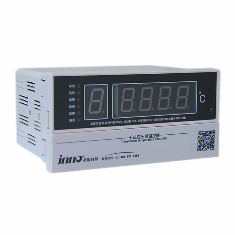
Ten thermal simulation winding temperature indicator (WTI) — also known as a hot-spot temperature simulator lub thermal image indicator — is a self-contained electromechanical instrument that estimates transformer winding hot-spot temperature using an analog thermal model of the transformer’s heat-rise behavior. It is one of the most widely installed transformer temperature monitoring devices in service globally, found on distribution and power transformers from 1 MVA to several hundred MVA.
Zasada działania
The WTI consists of a bimetallic dial thermometer installed in a PT100 oil temperature pocket on the transformer tank, combined with a small heating element energized by a current proportional to the transformer load current (supplied via a dedicated current transformer). The heater element mimics the I²R heat rise of the winding above oil temperature — so the thermometer pointer reads a temperature that represents the estimated winding hot spot rather than the oil temperature alone. By adjusting the heating current ratio and thermal time constant of the heater assembly, the WTI can be calibrated to closely match the actual winding thermal behavior defined in the transformer’s factory heat-run test report.
Funkcje funkcjonalne
- Provides a continuous estimated winding hot-spot temperature reading on a local analog dial — no external power supply required for basic indication
- Integral adjustable alarm and trip contacts (typically two independent contact stages) for direct connection to protection relay or SCADA alarm inputs
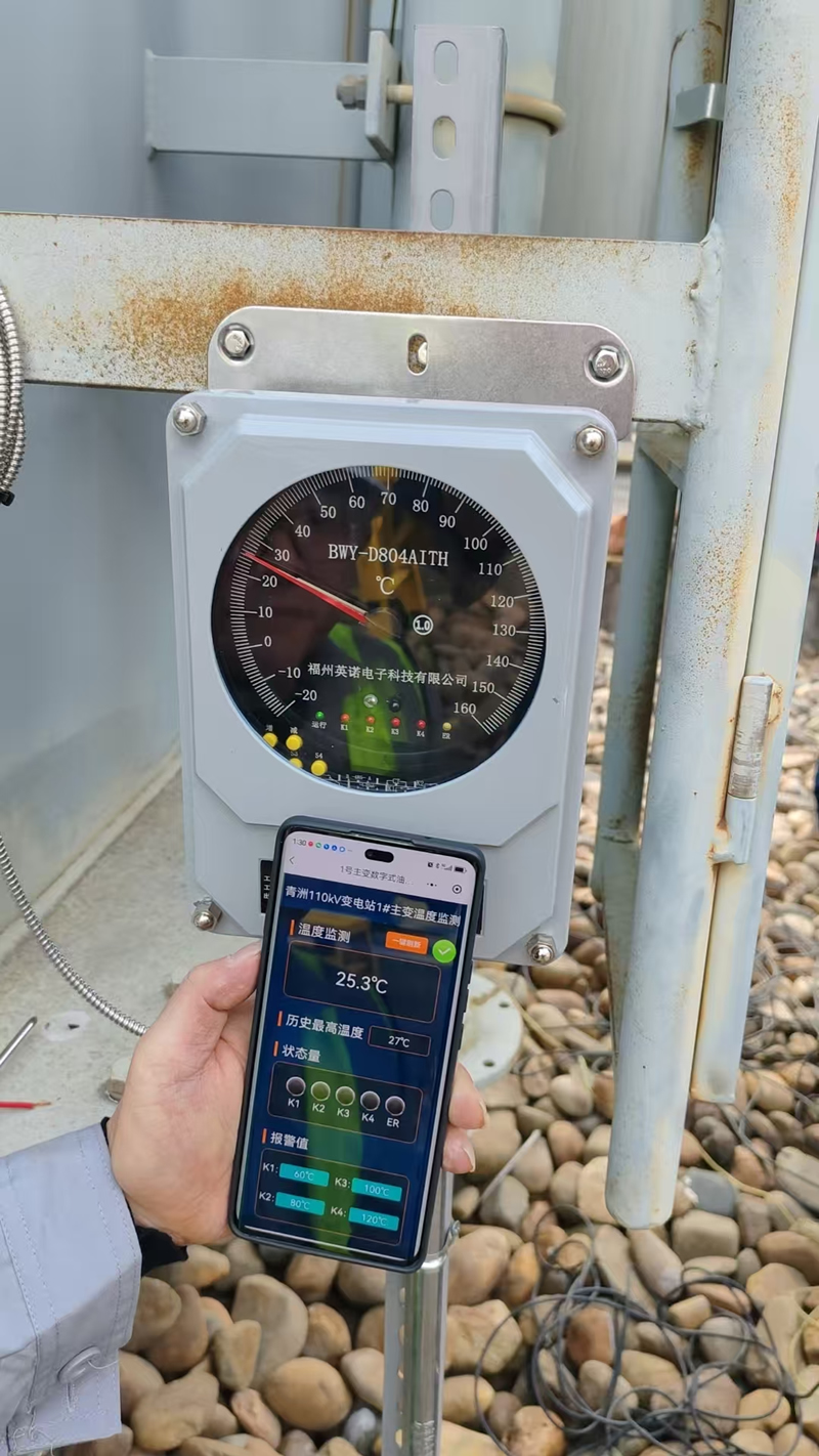
- Built-in drag-hand indicator rejestruje maksymalną temperaturę osiągniętą od ostatniego ręcznego resetu – przydatne do analizy zdarzeń przeciążenia po zdarzeniu
- Fakultatywny 4–20mA lub wyjście analogowe PT100 do integracji zdalnego monitorowania
- Oddzielny styki sterujące chłodzeniem do automatycznego włączania/wyłączania wentylatora lub pompy w oparciu o szacowaną temperaturę gorącego punktu
- Dostępne w obu wskaźnik temperatury oleju (ZROBIONE) konfiguracja (mierzy tylko górny olej, brak wejścia prądu obciążenia) i pełne wskaźnik temperatury uzwojenia (WTI) konfiguracja z kompensacją prądu obciążenia
Zastosowania i ograniczenia
Ten symulacja termiczna WTI jest standardowym urządzeniem zabezpieczającym przed temperaturą w większości transformatorów rozdzielczych i podtransmisyjnych używanych na całym świecie ze względu na niski koszt, mechaniczna prostota, i niezależność od zewnętrznych źródeł zasilania. Jednak, its analog thermal model is a simplified representation of actual winding thermal behavior — it does not account for non-uniform current distribution, localized cooling variations, or changes in winding thermal characteristics due to insulation aging. For critical high-value transformers where accurate hot-spot knowledge is essential for life management and dynamic load optimization, direct fiber optic winding temperature measurement should supplement or replace WTI-based thermal simulation.
Metoda 4: Wireless Temperature Monitoring Sensors
Wireless transformer temperature sensors use battery-powered transmitter nodes to collect surface temperature data at defined measurement points and relay readings to a central gateway or cloud monitoring platform via ZigBee, LoRa, 2.4GHz RF, or NB-IoT protokoły. This architecture eliminates signal cabling between the sensor and the monitoring system — a significant advantage for retrofit applications and installations where running new instrumentation cables to an existing transformer is impractical or costly.
Podstawowe zalety
- Tool-free installation on transformer external surfaces, końcówki tulejkowe, LV busbar connections, i końcówki kablowe
- Obsługuje multi-point networks covering dozens of measurement locations across a transformer bay or substation from a single gateway
- Real-time temperature data with configurable alarm thresholds and push notification to mobile devices or SCADA systems
- Idealny dla dry-type transformer enclosure monitoring where winding surface temperatures are the primary measurement target
- Cloud integration enables centralized monitoring and trending across multiple transformer installations on a single platform
Ograniczenia
Wireless sensors measure surface or near-surface temperatures only and cannot access the internal winding hot-spot of an oil-immersed transformer. Battery replacement is required typically every 2–5 years depending on transmission interval settings. Metal transformer enclosures attenuate radio frequency signals — antenna placement design and repeater positioning must be addressed during system commissioning to ensure reliable data transmission.
Metoda 5: Termografia w podczerwieni
Kamery termowizyjne na podczerwień detect the electromagnetic radiation emitted by transformer external surfaces and convert it into a calibrated visual heat map, enabling maintenance technicians to identify abnormal temperature gradients across bushings, połączenia terminalowe, cooling radiators, and tank surfaces during scheduled inspection visits without physical contact with energized equipment.
Handheld Infrared Camera vs. Fixed Online Thermal Sensor
Przenośny kamery termowizyjne na podczerwień are the standard tool for periodic transformer inspection rounds and provide high-resolution thermal images suitable for maintenance reports and trend comparison across successive inspection cycles. Naprawiono czujniki podczerwieni online mounted in dedicated observation windows on transformer enclosures or switchgear panels enable continuous thermal monitoring of specific external zones — bridging the gap between scheduled inspection intervals for high-priority assets.
Core Advantages and Limitations
Infrared thermography excels as a bezkontaktowy, rapid survey tool for external fault detection and maintenance documentation. It is fully compatible with all transformer types and voltage levels and requires no permanent installation on the transformer itself. Jednak, infrared measurement is fundamentally limited to surface temperature detection — it cannot measure winding hot-spot temperatures inside the transformer tank, and it provides only a periodic snapshot rather than the continuous real-time coverage needed for automated alarm and protection functions.
Monitorowanie temperatury transformatora: Tabela porównawcza technologii

| Kryteria | Fluorescencyjny światłowód | Czujnik PT100 | Thermal Simulation WTI | Czujnik bezprzewodowy | Termografia w podczerwieni |
|---|---|---|---|---|---|
| Typ pomiaru | Direct winding hot spot | Olej / surface temperature | Szacowany gorący punkt (obliczony) | Surface temperature | Surface temperature |
| Tryb monitorowania | Ciągłe w Internecie | Ciągłe w Internecie | Ciągłe w Internecie | Ciągłe w Internecie | Okresowy / zaplanowany |
| Odporność EMI | ★★★★★ | ★★★ | ★★★★ | ★★★ | ★★★★ |
| Dokładność pomiaru | ±0,5°C | ±0.3–1°C | ±2–5°C (estimated) | ±1°C | ±2°C |
| Internal Winding Access | ✅ Direct | ❌ Surface only | ⚠️ Calculated estimate | ❌ Surface only | ❌ External only |
| Alarm w czasie rzeczywistym | ✅ | ✅ | ✅ | ✅ | ❌ |
| Złożoność instalacji | Umiarkowany (factory or retrofit) | Prosty | Prosty | Minimalny | Nic (przenośny) |
| Suitable for Oil-Immersed | ✅ | ✅ | ✅ | ⚠️ External only | ✅ |
| Suitable for Dry-Type | ✅ | ✅ | ⚠️Ograniczona | ✅ | ✅ |
| IEC 60076-2 Uległy | ✅ | ⚠️ Indirect | ⚠️ Indirect | ❌ | ❌ |
| Najlepsza aplikacja | Critical HV transformers, winding life management | Standard protection relay input, oil monitoring | Transformatory rozdzielcze, routine thermal protection | Tuleja, LV terminals, dry-type retrofit | Maintenance inspection, external fault survey |
7. Building the Best Transformer Thermal Monitoring System
The most effective rozwiązanie do monitorowania temperatury transformatora is not a single device but a layered, integrated architecture that combines direct sensing, pozyskiwanie danych, zarządzanie alarmami, and system-level integration to deliver actionable thermal intelligence throughout the transformer’s operating life.
Warstwa 1 — Wyczuwanie: Matching Technology to Measurement Point
A comprehensive sensing deployment addresses all critical thermal zones of the transformer simultaneously. Fluorescencyjne sondy światłowodowe are embedded in the HV and LV winding assemblies at the factory-identified hot-spot locations to provide direct IEC 60076-2 compliant winding temperature readings. Czujniki PT100 are installed in the tank cover oil pocket for top oil temperature measurement and in radiator inlet/outlet pipes for cooling system monitoring. A thermal simulation winding temperature indicator (WTI) is mounted on the transformer marshalling panel to provide a local electromechanical backup indication and independent alarm contacts for protection relay tripping. Bezprzewodowe przetworniki temperatury są stosowane do złączy końcowych tulei, Złącza szyn zbiorczych nn, i końcówki kablowe w celu rozszerzenia zasięgu monitorowania na zewnętrzne punkty połączeń wysokiego ryzyka bez dodatkowego okablowania.
Warstwa 2 — Pozyskiwanie danych
Sygnały światłowodowe przetwarzane są przez: wielokanałowy demodulator fluorescencji który konwertuje pomiary czasu zaniku optycznego na skalibrowane wartości temperatury przy częstotliwości próbkowania 1–10 sekund. Sygnały PT100 podawane są bezpośrednio do przekaźnika zabezpieczającego transformator (Na przykład., ABB-RET670, Siemensa 7UT) lub do dedykowanego Moduł wejściowy RTD w systemie sterowania stacją. Dane z czujników bezprzewodowych są agregowane przez: Bramka LoRa lub ZigBee montowany w sterowni podstacji lub kiosku rozrządowym.
Warstwa 3 — Komunikacja i integracja
Wszystkie strumienie danych o temperaturze zbiegają się w systemie automatyki podstacji poprzez IEC 61850 Wiadomości GOOSE do transmisji alarmów o stopniu ochrony, Modbus TCP/RTU do integracji ze SCADA, i DNP3 for utility EMS connectivity. Cloud-connected deployments use MQTT over 4G/5G for remote monitoring and mobile alerting without dependence on substation LAN infrastructure.
Warstwa 4 — Monitoring Platform and Alarm Management
Ten transformer thermal monitoring software platform provides real-time temperature dashboards for all sensing points, historical trend logging with configurable retention periods, and a three-tier alarm management structure. Alarmy doradcze at 95°C winding hot spot initiate automated cooling system escalation. Alarmy ostrzegawcze at 110°C trigger operator notification and load reduction procedures. Alarmy krytyczne at 120°C (or the transformer manufacturer’s defined trip threshold) initiate automatic protection relay tripping to disconnect the transformer from service before thermal runaway occurs. All threshold values are configurable and should be validated against the transformer manufacturer’s thermal design data and the applicable loading guide (IEC 60076-7 lub IEEE C57.91).
Warstwa 5 — Automated Response and SCADA Integration
On alarm activation, the system executes a coordinated response sequence: cooling system fans and pumps are automatically started at full capacity; SMS-em, e-mail, and push notifications are dispatched to designated operations personnel; load shedding commands are issued to upstream protection relays if temperature continues to rise; and at the critical threshold, an automatic trip command is executed. Full integration with SCADA, EMS, CMMS, i platformy zarządzania aktywami ensures that all thermal events are logged with timestamped data, enabling post-event root cause analysis and regulatory compliance reporting.
Recommended System Configurations by Transformer Type
- Critical transmission transformer (≥100 MVA, 110kV i więcej): Fluorescent fiber optic winding sensors (factory-embedded, WN + LV) + PT100 top oil + WTI backup indicator + wireless bushing terminal sensors + full SCADA / IEC 61850 integracja
- Industrial oil-immersed transformer (10–100 MVA): Fluorescent fiber optic winding sensors + PT100 top oil and radiator monitoring + WTI with cooling control contacts + Modbus SCADA integration
- Dry-type cast-resin transformer: Fluorescencyjne sondy światłowodowe (embedded in winding during manufacture) + PT100 surface sensors + wireless LV busbar terminal sensors + local HMI display
- Distribution transformer retrofit: WTI replacement or upgrade + wireless surface sensors on bushing terminals + optional fiber optic probe insertion via tank cover port + cloud monitoring gateway
- Maintenance inspection program (all types): Periodic infrared thermographic surveys (minimum twice per year) combined with online monitoring data review for cross-validation and compliance documentation
8. Globalne studia przypadków: Transformer Temperature Monitoring in Action

The following real-world deployments illustrate how systemy monitorowania temperatury transformatorów have delivered measurable protection and operational value across a range of industries, poziomy napięcia, and geographic regions.
Studium przypadku 1 — Transmission Substation, Wielka Brytania
A major UK transmission network operator retrofitted fluorescent fiber optic winding temperature sensors into twelve 400kV autotransformers at a critical grid interconnection substation. Przed instalacją, the operators relied exclusively on thermal simulation WTI indicators and top oil PT100 measurements — neither of which provided direct knowledge of actual winding hot-spot conditions under dynamic load cycling. Within the first operating season following fiber optic sensor commissioning, the monitoring system identified two units operating with winding hot-spot temperatures 18–23°C above the WTI-indicated values under peak demand conditions — a discrepancy attributable to thermal model parameter drift in aging units. Load management protocols were adjusted accordingly, and both transformers were scheduled for planned inspection rather than facing the risk of an unplanned thermal failure during peak winter demand. The operator estimated the intervention prevented outage costs in excess of £2 million per affected unit.
Studium przypadku 2 — Data Center Campus, Singapur
A hyperscale data center operator managing eight dry-type cast-resin transformers at a Tier IV facility deployed a hybrid monitoring architecture combining factory-embedded fluorescent fiber optic probes w uzwojeniach WN i NN każdego transformatora z a bezprzewodowa sieć czujników temperatury zakrywające połączenia szyn zbiorczych nn, końcówki kablowe, i terminale wejściowe głównej tablicy rozdzielczej. Wszystko 96 punkty pomiarowe w ośmiu transformatorach przesyłane są do scentralizowanej platformy monitorowania w chmurze z mobilnymi powiadomieniami push skonfigurowanymi dla obiektu 24/7 zespół operacyjny. Podczas testu przeciążeniowego polegającego na zwiększaniu wydajności osiemnaście miesięcy po uruchomieniu, system światłowodowy wykrył temperaturę gorącego punktu uzwojenia wynoszącą 158°C w jednym transformatorze — 23°C powyżej wskazania powierzchni WTI — powodując natychmiastowe przeniesienie obciążenia do jednostki rezerwowej. Analiza termiczna po zdarzeniu potwierdziła, że w izolacji żywicy transformatora, której dotyczy problem, zaczęły pojawiać się mikropęknięcia powierzchniowe, zgodne z długotrwałym narażeniem na przegrzanie, validating the system’s early intervention.
Studium przypadku 3 — Rail Traction Power Substation, Chiny
A metropolitan railway operator equipped traction power substations across 24 stations with multi-channel fluorescent fiber optic thermometry systems monitoring winding hot spots in Scott-connection traction transformers. The high-frequency switching transients and strong electromagnetic fields generated by traction inverter systems ruled out conventional PT100-based winding monitoring — electronic sensors in this environment experienced persistent measurement noise and false alarms. The all-optical fiber sensing architecture eliminated EMI-related false alarms entirely while delivering ±0.5°C winding hot-spot accuracy throughout the network. The system interfaces directly with the railway’s SCADA energy management system za pośrednictwem IEC 61850, umożliwiając zautomatyzowaną kontrolę chłodzenia i optymalizację rozłożenia obciążenia w oparciu o zapas ciepła w czasie rzeczywistym w każdym transformatorze trakcyjnym.
Studium przypadku 4 — Rafineria Petrochemiczna, Arabia Saudyjska
Główny operator rafinerii zarządzający czternastoma 11Transformatory blokowe zanurzone w oleju kV w strefach sklasyfikowanych jako niebezpieczne wdrożono kompleksową modernizację monitoringu łączącą Górne czujniki oleju PT100 z certyfikatem ATEX, thermal simulation WTI indicators ze zdalnymi wyjściami 4–20 mA, i iskrobezpieczne bezprzewodowe przetworniki temperatury na zaciskach przepustowych transformatora i skrzynkach przyłączeniowych kabli WN. Sieć bezprzewodowa wyeliminowała potrzebę prowadzenia nowych kabli oprzyrządowania w zatłoczonych korytkach kablowych w sklasyfikowanych obszarach — co stanowi znaczną zaletę w zakresie bezpieczeństwa i kosztów. The integrated monitoring platform flagged an abnormal bushing terminal temperature rise of 41°C above ambient on one transformer within six weeks of commissioning, leading to the discovery of a severely under-torqued terminal clamp that had been missed during the previous scheduled maintenance outage.
Studium przypadku 5 — Wind Farm Collector Substation, Niemcy
A renewable energy developer commissioned a 250 MVA offshore wind farm collector transformer equipped with factory-embedded fluorescent fiber optic probes in both HV and LV windings, w połączeniu z PT100 top oil sensors, radiator differential temperature monitoring, i a WTI indicator providing independent local backup protection. The fiber optic system feeds real-time hot-spot data to the wind farm SCADA platform, enabling dynamic transformer loading optimization — allowing the operator to safely push transformer output above nameplate rating during periods of favorable ambient temperature and wind resource, while automatically curtailing generation when hot-spot temperatures approach the IEC 60076-7 emergency loading threshold. The dynamic loading capability increased annual energy yield by an estimated 3.2% compared to conservative fixed nameplate-limited operation.
Często zadawane pytania: Monitorowanie temperatury transformatora
1. Why is transformer temperature monitoring so important?
Transformer insulation — primarily cellulose paper in oil-filled units and cast resin in dry-type units — degrades irreversibly with heat exposure. According to the Arrhenius thermal aging model codified in IEC 60076-7, every 6–10°C of sustained overtemperature halves the remaining insulation life. Bez continuous transformer temperature monitoring, thermal degradation proceeds invisibly until insulation failure causes an unplanned outage, ogień, or catastrophic transformer loss. Proactive monitoring enables condition-based maintenance, dynamic load management, and timely intervention before thermal damage becomes irreversible.
2. What is the difference between a winding temperature indicator (WTI) and a direct fiber optic winding sensor?
A thermal simulation winding temperature indicator (WTI) estimates winding hot-spot temperature using an analog thermal model — it measures top oil temperature and adds a calculated temperature increment proportional to load current. This estimate carries inherent uncertainty of ±2–5°C or more, particularly under dynamic load conditions or when the transformer’s thermal characteristics have changed due to aging. A fluorescent fiber optic winding sensor measures the actual temperature at the physical hot-spot location inside the winding — providing a direct, real-time reading with ±0.5°C accuracy that requires no thermal model assumptions. For critical high-value transformers, direct fiber optic measurement provides significantly higher confidence in thermal condition assessment than WTI simulation alone.
3. What temperature should trigger a transformer winding alarm?
Alarm thresholds depend on transformer insulation class, design rating, and applicable loading standard. For standard mineral-oil transformers with Class A cellulose insulation, IEC 60076-7 defines a continuous hot-spot limit of 98°C for normal cyclic loading, z emergency loading limits up to 140°C for short-duration contingency operation. Typical protection relay settings use a first-stage alarm at 100–110°C winding hot spot to initiate cooling escalation and operator notification, z second-stage trip at 120–130°C to automatically disconnect the transformer. For dry-type cast-resin transformers, thermal class F (155°C) and class H (180°C) windings carry higher permissible operating temperatures — consult the transformer manufacturer’s documentation for model-specific settings.
4. Can fluorescent fiber optic probes be retrofitted into an existing oil-immersed transformer?
Tak, in many cases. Retrofit installation of fluorescent fiber optic sensors in existing oil-immersed transformers is technically feasible during planned maintenance outages when the transformer is de-energized and oil drained or partially lowered. Probes are inserted through the transformer tank cover via dedicated fiber feedthrough fittings and guided into the winding assembly using flexible insertion tools. The specific feasibility depends on winding construction, available tank access points, and the transformer manufacturer’s guidance. For new transformer procurement, specifying factory-installed fiber optic probes during manufacture is the preferred approach as it ensures optimal sensor placement at the design hot-spot location.
5. What is the difference between top oil temperature and winding hot-spot temperature?
Najwyższa temperatura oleju is the temperature of the insulating oil at the highest point in the transformer tank — measured by a Czujnik PT100 in the tank cover pocket. It represents the bulk thermal state of the transformer’s cooling medium. Temperatura gorącego punktu uzwojenia is the highest temperature point within the winding conductor and insulation assembly — typically located in the upper portion of the coil and consistently higher than the surrounding oil temperature by 15–40°C depending on load level and cooling mode. It is the winding hot-spot temperature, not the top oil temperature, that directly governs insulation aging rate and permissible loading capacity. Relying on top oil temperature alone systematically underestimates the thermal stress on transformer insulation.
6. Do transformer temperature monitoring systems need to comply with IEC standards?
Tak. The primary applicable standards for monitorowanie temperatury transformatora Czy IEC 60076-2 (Temperature rise for liquid-immersed transformers — defines hot-spot measurement methodology), IEC 60076-7 (Przewodnik obciążenia dla transformatorów mocy zanurzonych w oleju - określa model starzenia termicznego i limity obciążenia), i IEC 60354 (Przewodnik ładowania dla transformatorów mocy zanurzonych w oleju, zastąpiony przez IEC 60076-7 ale nadal wspominane). Do transformatorów suchych, IEC 60076-11 ma zastosowanie. Następuje integracja przekaźnika zabezpieczającego i systemu monitorowania IEC 61850 do komunikacji automatyki podstacji. Kupujący powinni potwierdzić, że proponowane systemy monitorowania są zaprojektowane zgodnie z tymi normami i że dokładność czujników i identyfikowalność kalibracji są odpowiednio udokumentowane.
7. Czy bezprzewodowy monitoring temperatury nadaje się do stosowania w kadziach transformatorów zanurzonych w oleju??
Nie. Bezprzewodowe czujniki temperatury to urządzenia elektroniczne wymagające zasilania bateryjnego i transmisji sygnału na częstotliwości radiowej — żadne z nich nie jest kompatybilne z wnętrzem kadzi transformatora wypełnionej olejem pod napięciem. Czujniki bezprzewodowe są odpowiednie do zastosowań związanych z zewnętrznym monitorowaniem powierzchni transformatora: połączenia końcówek tulejowych, Złącza szyn zbiorczych nn, skrzynki przyłączeniowe kabli, i suche powierzchnie obudów transformatorów. Do monitorowania gorących punktów uzwojenia wewnętrznego transformatorów zanurzonych w oleju, fluorescencyjne czujniki światłowodowe to jedyna technologia, którą można bezpiecznie zainstalować wewnątrz kadzi transformatora pod napięciem.
8. Jak długo wytrzymują fluorescencyjne światłowodowe czujniki temperatury w eksploatacji transformatora?
Fluorescencyjne sondy światłowodowe to pasywne elementy optyczne niezawierające aktywnych elementów elektrycznych, ruchome części, lub materiałów eksploatacyjnych w punkcie wykrywania. W normalnych warunkach pracy transformatora – łącznie z ciągłym zanurzeniem w oleju mineralnym, cykle termiczne pomiędzy temperaturą otoczenia i znamionową gorącego punktu, oraz narażenie na rozpuszczone gazy i wilgoć – udokumentowany okres eksploatacji w terenie przekracza 20–25 years without degradation of measurement accuracy or sensor integrity. The external demodulator electronics have a typical design life of 10–15 years with routine maintenance. This long service life makes fiber optic sensing a cost-effective investment over the full operational life of the transformer asset.
9. Can a transformer temperature monitoring system integrate with existing SCADA or EMS platforms?
Tak. All major systemy monitorowania temperatury transformatorów support the standard industrial communication protocols required for SCADA, EMS, and substation automation integration. Common supported protocols include IEC 61850 (GOOSE and MMS) for protection-grade substation communication, Modbus RTU/TCP for general SCADA connectivity, DNP3 for utility EMS and telecontrol systems, i MQTT over 4G/5G for cloud-based remote monitoring deployments. Integracja z skomputeryzowane systemy zarządzania utrzymaniem ruchu (CMMS) i digital asset management platforms umożliwia automatyczne generowanie zleceń pracy w przypadku zdarzeń alarmowych i ciągłe śledzenie trendów wskaźników stanu termicznego transformatora wraz z innymi strumieniami danych monitorowania stanu.
10. Jak wybrać najlepsze rozwiązanie do monitorowania temperatury transformatora dla mojego konkretnego zastosowania??
Optymalne rozwiązanie zależy od czterech głównych czynników. Pierwszy, typ transformatora i poziom napięcia: Jednostki zanurzone w oleju powyżej 10 kV odnoszą największe korzyści z bezpośredniego monitorowania uzwojenia światłowodu; Jednostki typu suchego są dobrze obsługiwane przez wbudowane sondy światłowodowe połączone z bezprzewodowymi czujnikami powierzchniowymi. Drugi, krytyczność i koszt wymiany: transformatory transmisyjne powyżej 100 MVA z terminem wymiany wynoszącym 12–24 miesięcy uzasadnia kompleksowe monitorowanie światłowodów; transformatory rozdzielcze mogą być odpowiednio zabezpieczone przez WTI plus PT100 z okresową inspekcją w podczerwieni. Trzeci, nowa konstrukcja vs. modernizacja: factory-embedded fiber optic probes are the most cost-effective approach for new transformers; retrofit projects should evaluate the feasibility of probe insertion versus wireless external monitoring as the primary upgrade path. Czwarty, integration requirements: facilities with existing SCADA or IEC 61850 substation automation infrastructure should specify monitoring systems with native protocol support to avoid costly middleware integration. Contact a specialist transformer monitoring supplier to obtain a site-specific system recommendation based on your transformer nameplate data, ładowanie profilu, i cele monitorowania.
Get the Right Transformer Temperature Monitoring Solution for Your Project
Whether you are commissioning a new high-voltage power transformer, upgrading protection on aging critical assets, or building a fleet-wide thermal monitoring program across multiple substations, selecting the right combination of fluorescencyjne czujniki światłowodowe, PT100 detectors, thermal simulation indicators, and wireless monitoring technology is a decision that directly affects transformer longevity, niezawodność działania, and personnel safety.
Fjinno (Fuzhou Innowacja Elektroniczna Scie&Technologia Co., z oo) specjalizuje się w fluorescent fiber optic transformer temperature monitoring systems with over a decade of deployment experience across high-voltage switchgear, transformatory mocy, Sprzęt GIS, transformatory suche, and rail traction power systems. Nasz zespół inżynierów zapewnia projekt systemu dostosowany do konkretnego zastosowania, kalibracja fabryczna, wsparcie instalacji, and long-term technical service for projects at all scales — from single-transformer protection upgrades to multi-site utility monitoring programs.
- 📧 E-mail: web@fjinno.net
- 📱 Sieć WhatsApp / Czat WeChat / Telefon: +86 135 9907 0393
- 💬 QQ: 3408968340
- 🌐 Strona internetowa: www.fjinno.net
- 📍 Adres: Liandong U Grain Networking Park Industrial Park, Nr 12 Xingye West Road, Fuzhou, Fujian powiedział:, Chiny
Zastrzeżenie: Informacje techniczne, progi temperaturowe, and standard references in this article are provided for general guidance purposes only. Specific transformer protection settings, specyfikacje czujnika, and system configurations must be determined by qualified electrical engineers in accordance with the transformer manufacturer’s documentation, applicable IEC and IEEE standards, oraz lokalne wymagania prawne. Always follow established safety procedures when working on or near energized electrical equipment.

Światłowodowy czujnik temperatury, Inteligentny system monitorowania, Rozproszony producent światłowodów w Chinach
 |
 |
 |