Mawu Oyamba
Switchgear is critical electrical equipment in power systems, with bus bar connections, circuit breaker contacts, and other components prone to heating during long-term operation. Fluorescence fiber optic temperature measurement technology, with its unique advantages, provides a reliable solution for switchgear temperature monitoring.
Components of a Fluorescence Fiber Optic Temperature Measurement System
- Fluorescence Fiber Optic Temperature Sensors: These core components are made from fluorescent materials that convert temperature information into fluorescence signals, enabling real-time temperature monitoring.
- Fiber Optic Transmission Lines: Used to transmit fluorescence signals from sensors to the signal processing unit, featuring excellent insulation properties and electromagnetic interference resistance to ensure stable and reliable signal transmission.
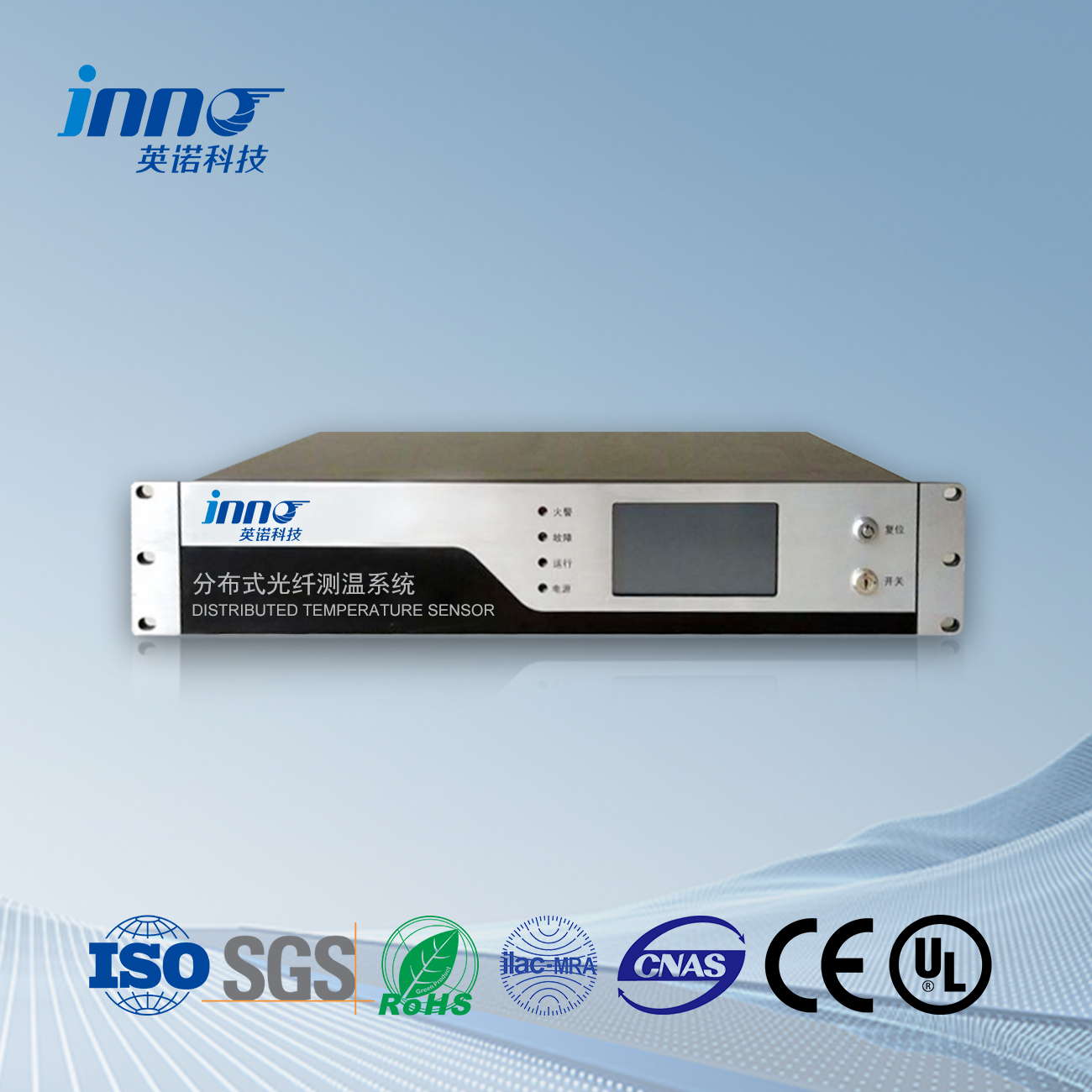
- Signal Processing Unit: Processes and analyzes received fluorescence signals, extracts temperature information, and transmits temperature data to monitoring systems or host computers through communication interfaces.
- Monitoring and Display Unit: Displays real-time temperature values from various measurement points within the switchgear and includes alarm functionality. When temperatures exceed set thresholds, timely alarm signals alert maintenance personnel to take appropriate measures.
Pre-Installation Preparation
- Tool Preparation: Prepare necessary installation tools, including fiber optic cutting tools.
- Personnel Training: Ensure installation personnel understand the principles and installation procedures of fluorescence fiber optic temperature measurement systems, master techniques for routing, connecting, and securing optical fibers, and are familiar with safety precautions.
- Installation Environment Inspection: Check the switchgear installation environment to ensure it meets the requirements for fluorescence fiber optic temperature measurement systems. The interior of the switchgear should be clean, dry, and free of dust, oil, and moisture. Additionally, examine the cabinet’s internal layout to ensure sufficient space for installing wiring components.
Detailed Installation Steps
-
Determining Installation Locations
Based on the switchgear structure and electrical equipment layout, select appropriate temperature measurement points, typically including bus bar connections, circuit breaker contacts, cable connectors, and other heat-prone areas, as well as other critical equipment within the switchgear. Simultaneously, plan the fiber optic routing path, avoiding parallel installation with high-current lines to reduce electromagnetic interference, and ensuring the fiber’s bending radius meets requirements.
-
Installing Fluorescence Fiber Optic Probes
Install the fluorescence fiber optic probes at the determined measurement points. For areas such as bus bar connections, use specialized mounting fixtures to secure probes firmly to the surface of the object being measured, ensuring good thermal contact between the probe and the object. During installation, take care to protect the probes from mechanical damage or contamination.
-
Laying Optical Fibers
Following the planned routing path, lay optical fibers within the switchgear. Secure the fibers along cabinet walls or equipment surfaces, using cable ties or other fasteners to bind the fibers to internal structures or equipment. Exercise care not to apply excessive force that might damage the fibers. During installation, avoid creating bends with radii smaller than specified, twisting, knotting, or other damaging configurations. Protect fibers from sharp objects that could scratch or compress them. For excess fiber sections, coil and secure them appropriately, ensuring the coil diameter exceeds the specified minimum bending radius and that the fibers are firmly secured to prevent loosening due to vibration or other factors.
-
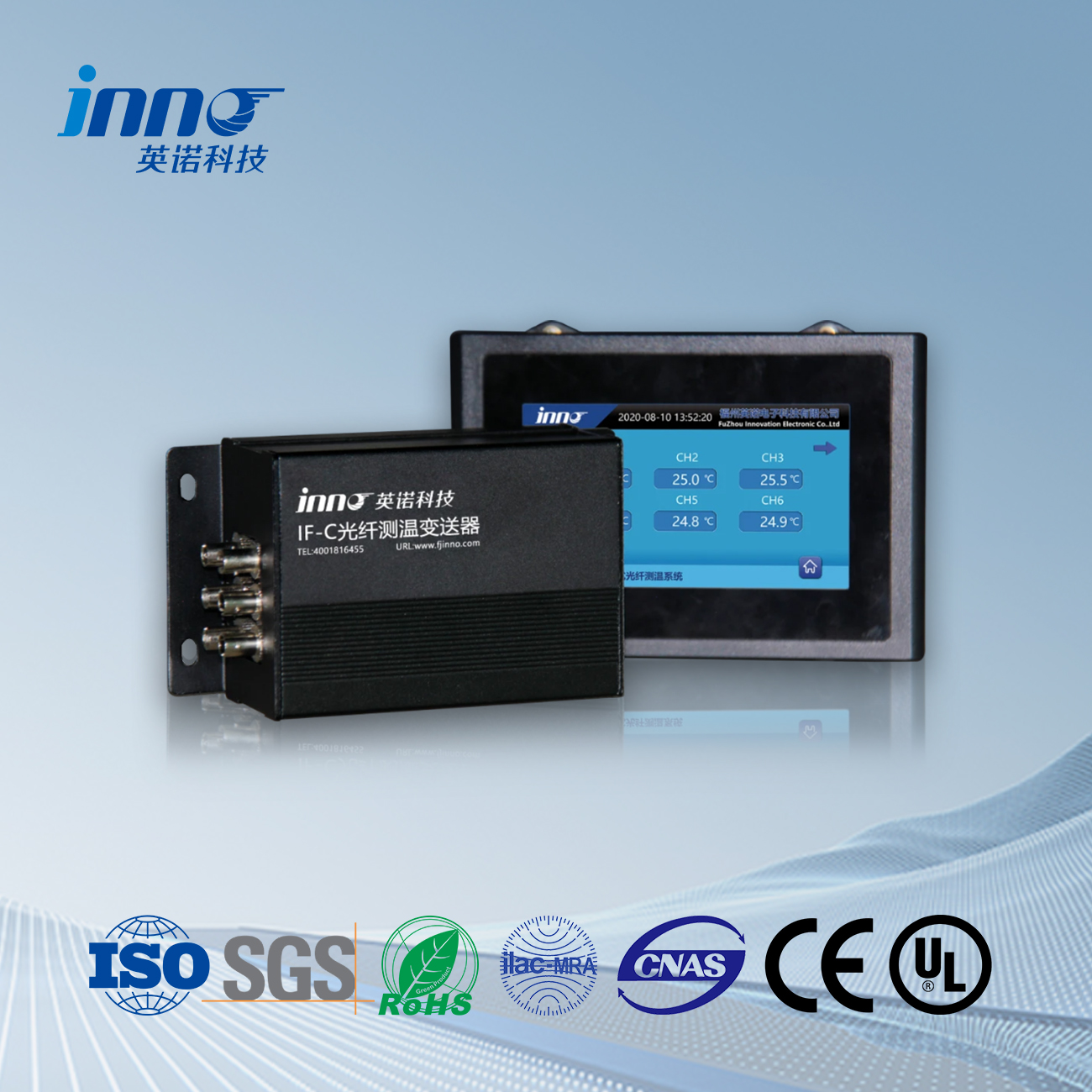
Connecting Optical Fibers to Temperature Transmitters
Connect the installed optical fibers to the fluorescence fiber optic temperature transmitters. Temperature transmitters are typically installed in the switchgear’s instrument room and connected to optical fibers via ST connectors or other appropriate connection methods. During connection, ensure the ST connectors are clean and dust-free, following correct procedures to connect the fibers securely to the transmitter, avoiding false connections or misalignment issues.
-
Installing Temperature Transmitters
Install the fluorescence fiber optic temperature transmitters in the switchgear’s instrument room. Installation methods may include rail mounting or screw fixation, ensuring transmitters are firmly and stably installed, and accessible for future maintenance and repair.
-
Connecting Power and Communication Lines
Connect the temperature transmitter’s power lines to the switchgear’s power supply, typically requiring a 24V DC power source, and ensure stable and reliable power supply. Simultaneously, connect the transmitter’s communication lines to monitoring systems or host computers as needed, enabling remote transmission and monitoring of temperature data.
-
Installing Monitoring and Display Units
Install monitoring and display units in locations convenient for observation and operation, such as on the switchgear panel or in the control room. Connect these units to temperature transmitters via communication lines, ensuring temperature data is displayed accurately and in real-time on the monitoring interface, with alarm functions operating normally.
Post-Installation Commissioning and Considerations
-
System Commissioning
After installation, commission the entire fluorescence fiber optic temperature measurement system. Verify normal signal transmission from fiber optic sensors, ensuring temperature data is accurately transmitted from sensors to signal processing units and correctly displayed on monitoring and display units. Additionally, set temperature alarm thresholds according to switchgear operational requirements and equipment temperature limits, ensuring the system issues timely alarm signals when temperatures are abnormal.
-
Calibration and Verification
Calibrate the fluorescence fiber optic temperature measurement system using standard temperature sources or by comparison with other temperature measurement equipment of known accuracy, ensuring the system’s precision and reliability. During commissioning, promptly troubleshoot and resolve any issues if abnormal temperature data or system faults are detected, ensuring normal system operation.
-
Regular Maintenance and Inspection
During switchgear operation, regularly maintain and inspect the fluorescence fiber optic temperature measurement system. Check the security of optical fibers, ensuring they have not loosened, been damaged, or been subjected to external interference; clean fiber surfaces and fluorescence fiber optic probes to prevent dust, oil, or other contaminants from affecting temperature measurement accuracy; inspect temperature transmitters and monitoring and display units to ensure normal operation; periodically calibrate the temperature measurement system to maintain accuracy. Additionally, observe temperature changes at measurement points within the switchgear, promptly identifying and addressing temperature abnormalities to ensure safe and stable switchgear operation.
Installation Case Study
In a switchgear renovation project at a substation, a fluorescence fiber optic temperature measurement system was successfully implemented. The project team first conducted a detailed assessment of the switchgear’s structure and operational status, identifying multiple critical temperature measurement points, including bus bar connections, circuit breaker contacts, and cable connectors. During installation, they strictly followed installation procedures, ensuring fluorescence fiber optic probes maintained close contact with measured objects and properly routing optical fibers to avoid electromagnetic interference and mechanical damage. After installation, commissioning, and calibration, the system accurately monitored temperature changes at various measurement points within the switchgear and issued timely alarm signals. Through this system, maintenance personnel could monitor switchgear temperature conditions in real-time, promptly identifying and addressing temperature abnormalities caused by poor contacts and other issues, effectively preventing equipment failures and power outages, and enhancing the substation’s power supply reliability and operational safety.
Conclusion
The application of fluorescence fiber optic temperature measurement technology in switchgear temperature monitoring provides robust protection for the safe operation of electrical equipment. The installation process must strictly adhere to standards, with thorough preparation, appropriate selection of installation locations, careful fiber routing, correct equipment connections, and detailed commissioning and calibration. Through regular maintenance and inspection, the long-term stable operation of fluorescence fiber optic temperature measurement systems can be ensured, providing timely and accurate monitoring of switchgear temperature changes, preventing equipment failures and accidents, and establishing a solid foundation for the safe and reliable operation of power systems.
Fiber optic kutentha sensor, Njira yowunikira mwanzeru, Kugawidwa kwa fiber optic wopanga ku China
 |
 |
 |
 INNO CHIKWANGWANI chamawonedwe kutentha masensa ,machitidwe oyang'anira kutentha.
