 Penderia suhu gentian optik INNO ,sistem pemantauan suhu.
- Alat suis bertebat gas (GIS) menumpukan komponen voltan tinggi dalam kedap, Petak yang dipenuhi SF₆ di mana walaupun kecacatan penebat kecil boleh meningkat kepada kegagalan bencana dengan masa pembaikan yang sangat lama — menjadikan pemantauan pelepasan separa yang dipertingkatkan penting dan bukannya pilihan.
- UHF (Frekuensi Ultra Tinggi) pengesanan dalam 300 MHz–3 000 Jalur MHz ialah kaedah pilihan untuk GIS kerana penutup logam bertindak sebagai perisai elektromagnet semula jadi, menyediakan nisbah isyarat-ke-bunyi yang luar biasa yang tidak dapat dipadankan oleh teknik pengesanan PD lain dalam persekitaran ini.
- Sistem pemantauan PD GIS moden dengan 5 sensitiviti pC, 4–6 saluran pemerolehan, dan 3D analisis pola PRPD boleh mengenal pasti dan mengklasifikasikan korona, permukaan, batal, dan pelepasan berpotensi terapung — menukar isyarat mentah kepada keputusan penyelenggaraan yang boleh diambil tindakan.
- lancar Penyepaduan SCADA melalui IEC 61850, Modbus, and DNP3 embeds GIS insulation health data into the substation automation layer, enabling condition-based maintenance at fleet scale.
Jadual Kandungan
- Why GIS Demands a Different Approach to Partial Discharge Monitoring
- How PD Occurs Inside Gas Insulated Switchgear — Failure Mechanisms
- Why UHF Is the Superior Detection Method for GIS Partial Discharge
- Core Architecture of an Enhanced GIS PD Monitoring System
- UHF Sensor Specifications That Determine Detection Performance
- Multi-Channel Acquisition Host — Technical Parameters
- PRPD Pattern Analysis — Identifying Discharge Types in GIS
- Backend Software and SCADA Integration
- Installation and Deployment Considerations for GIS Environments
- How to Choose a GIS PD Monitoring System — Selection Criteria
- Soalan Lazim (Soalan Lazim)
1. kenapa GIS Demands a Different Approach to Partial Discharge Monitoring
Gas insulated switchgear is not simply a transformer or cable in a different package — it presents a fundamentally different monitoring challenge. All active components — busbars, pemutus litar, pemutus sambungan, transformer semasa, and bushings — are enclosed within grounded metallic housings filled with pressurised SF₆ gas. This sealed architecture eliminates visual inspection, prevents direct acoustic coupling to external sensors, and makes conventional IEC 60270 electrical PD measurements impractical in the field.
Pada masa yang sama, the consequences of an undetected insulation fault in GIS are disproportionately severe. A single compartment failure can require months of repair because replacement parts are custom-manufactured and the gas handling, pembongkaran, and re-commissioning process is complex and time-consuming. For transmission-voltage GIS operating at 110 kV, 220 kV, atau 500 kV, the resulting outage can affect grid stability across an entire region. This combination of limited inspectability and high failure consequence is precisely why enhanced online partial discharge monitoring has become a standard requirement for GIS installations worldwide.
2. How PD Occurs Inside Gas Insulated Switchgear — Failure Mechanisms
Partial discharge inside GIS is driven by localised electric field concentrations that exceed the dielectric strength of the SF₆ gas or the solid insulating spacers. Four root causes account for the vast majority of GIS PD events.
Free metallic particles — small conductive fragments left behind during manufacturing or generated by mechanical wear of contacts — are the single most common cause of PD in GIS. These particles can migrate under electrostatic forces, settle on spacer surfaces, or become trapped in high-field regions, creating corona or surface discharge. Contamination on spacer surfaces, whether from moisture, habuk, or handling residue, reduces surface flashover voltage and initiates tracking discharge along the solid–gas interface. Voids or delaminations within cast-resin spacers create gas pockets where the breakdown voltage is lower than the surrounding solid, leading to repetitive internal discharge. Floating metallic components — shields, electrodes, or bolts that have lost their electrical connection — acquire an indeterminate potential through capacitive coupling and drive high-energy discharge against adjacent grounded or energised structures.
Each of these mechanisms produces a distinct electromagnetic signature that a properly designed UHF monitoring system can detect, classify, and track over time.
3. Why UHF Is the Superior Detection Method for GIS Partial Discharge
Several PD detection methods exist — electrical (IEC 60270), pelepasan akustik, voltan bumi sementara (TEV), and UHF — but the physics of GIS operation overwhelmingly favour the UHF approach for permanent online monitoring.
When a partial discharge pulse occurs inside a GIS compartment, it radiates electromagnetic energy across a broad frequency spectrum. The metallic enclosure of the GIS acts as a waveguide, allowing UHF signals in the 300 MHz–3 000 MHz range to propagate efficiently along the bus duct with relatively low attenuation. Yang penting, the same metallic enclosure shields UHF sensors from external electromagnetic interference — radio broadcasts, menukar transien, corona from overhead lines — that would overwhelm lower-frequency detection methods in a substation environment. This natural shielding effect gives UHF detection an inherent signal-to-noise advantage that no other method can replicate inside GIS.
By comparison, TEV sensors measure voltage transients on the outer enclosure surface. While useful for portable spot-checks, TEV has lower sensitivity to internal defects, cannot reliably distinguish PD types, and is more susceptible to external noise. Acoustic sensors struggle with the multiple reflections and attenuation paths inside the metal-enclosed gas volume. The IEC 60270 electrical method, though highly accurate in laboratory settings, requires coupling capacitors that are impractical to retrofit on operational GIS. For continuous, installed monitoring of GIS, UHF is the clear technical choice.
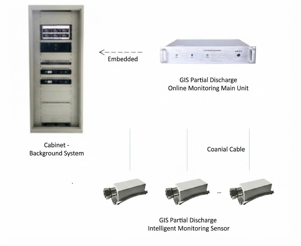
4. Core Architecture of an Enhanced GIS PD Monitoring System
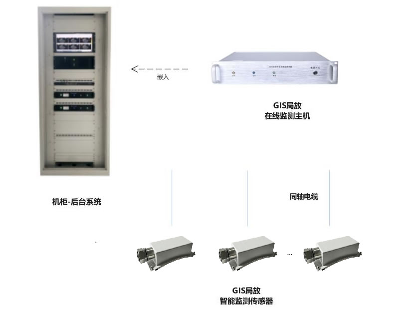
A complete GIS PD monitoring installation comprises three layers: field sensors, a centralised acquisition and processing host, and backend diagnostic software. The architecture is designed so that each layer performs a specific function and communicates seamlessly with the next.
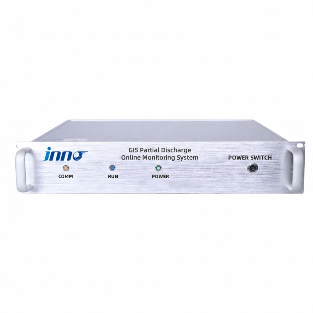
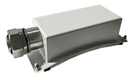
Penderia UHF are installed at strategic points on the GIS — typically at spacer joints, penamatan kabel, and bushing interfaces where PD is most likely to originate. Each sensor captures the electromagnetic radiation produced by discharge events and transmits the signal via coaxial cable to the monitoring host. The acquisition host, housed in a 2U rack-mount enclosure, receives signals from multiple sensors simultaneously, performs high-speed digitisation and signal conditioning (demodulation, pengurangan bunyi, penguatan), and computes key PD parameters including discharge magnitude, phase angle, and repetition rate. The host then transmits processed data over Ethernet to the platform perisian bahagian belakang, which provides real-time visualisation, analisis corak PRPD, pengurusan penggera, trend sejarah, and integration with the substation SCADA system.
5. UHF Sensor Specifications That Determine Detection Performance
The sensor is the first and most critical link in the detection chain. Its specifications directly determine whether the system can detect incipient PD or only advanced faults. The table below details the key parameters of a high-performance UHF sensor designed specifically for GIS applications.
| Parameter | Spesifikasi | Mengapa Ia Penting |
|---|---|---|
| Jalur Frekuensi Pemantauan | 300 – 3 000 MHz | Covers the full UHF range where GIS PD signals propagate most efficiently inside the metallic enclosure |
| Sensitiviti | 5 pC | Detects very small incipient discharges before they escalate to damaging levels |
| Padanan Impedans | 50 Oh | Standard RF impedance ensures maximum power transfer from sensor to coaxial cable with minimal reflection loss |
| VSWR (Voltage Standing Wave Ratio) | ≤ 2 | Low standing wave ratio confirms efficient signal transmission; VSWR yang lebih tinggi menyebabkan kemerosotan isyarat dan ralat pengukuran |
| Directivity | Omnidirectional | Kepekaan yang sama dalam semua arah menghilangkan keperluan untuk penjajaran sudut yang tepat semasa pemasangan |
| Antaramuka Output | Penyambung RF jenis N | Penyambung standard industri menyediakan yang boleh dipercayai, sambungan berulang dengan rintangan sentuhan rendah |
| Panjang Kabel Sepaksi | Standard 10 m (boleh disesuaikan) | Menampung jarak biasa antara GIS dan kabinet pemantauan; panjang tersuai tersedia untuk pemasangan besar |
| Suhu Operasi | -40 °C hingga +85 °C | Menyokong penggunaan dalam iklim ekstrem — daripada pencawang arktik kepada persekitaran padang pasir yang melebihi 50 °C |
| Toleransi Kelembapan | ≤ 95 % RH | Dinilai untuk lokasi tropika dan pantai dengan kelembapan tinggi yang berterusan |
Gabungan daripada 5 sensitiviti pC dan VSWR sebanyak ≤ 2 amat penting. Kepekaan menentukan pelepasan terkecil yang dapat dikesan oleh sistem; VSWR determines how much of that signal actually reaches the acquisition host without being reflected back along the cable. A system with high stated sensitivity but poor VSWR will lose a significant fraction of the detected signal in transit, effectively negating its sensitivity advantage.
6. Multi-Channel Acquisition Host — Technical Parameters
The acquisition host is the processing core of the system, responsible for digitising, conditioning, and analysing signals from all connected sensors. The table below presents the core specifications of the monitoring host unit.
| Parameter | Spesifikasi |
|---|---|
| Kekerapan Pemantauan | 300 – 3 000 MHz |
| Bilangan Saluran | 4 atau 6 (selectable) |
| Antaramuka Komunikasi | RJ45 Ethernet + RS-485 |
| Protokol yang Disokong | Modbus RTU / TCP, IEC 61850, DNP3 |
| Bekalan Kuasa | AC 90 – 240 V, 50/60 Hz |
| Kepungan | 2U rack-mount (483 mm × 89 mm × 300 mm) |
| Cabinet Protection Rating | IP54 |
| Pemprosesan Isyarat | Demodulation, pengasingan, pengurangan bunyi, penguatan, pemerolehan berkelajuan tinggi, multi-cycle periodic measurement |
| Output Diagnostik | Maximum discharge magnitude, magnitud pelepasan purata, kekerapan pelepasan, 3D corak PRPD, trend statistics |
Pilihan antara 4 dan 6 channels depends on the GIS configuration. A single-bay GIS with three compartments can be fully covered by a 4-channel host, while extended bus sections or double-bus arrangements benefit from the additional capacity of a 6-channel unit. The modular channel architecture also means the system can be deployed initially with fewer sensors and expanded later without replacing the host hardware.
7. PRPD Pattern Analysis — Identifying Discharge Types in GIS

Detecting that partial discharge is occurring is only the first step. The real diagnostic value lies in identifying what type of discharge it is, because each type implies a different defect mechanism, a different severity trajectory, and a different maintenance response.
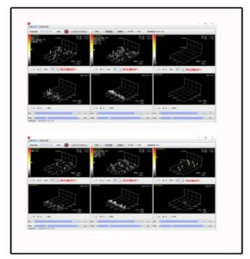
Pelepasan Separa Selesai Fasa (PRPD) analysis achieves this by mapping each detected PD pulse onto a three-dimensional coordinate system: discharge magnitude on the vertical axis, phase angle of the power-frequency cycle on the horizontal axis, and pulse density represented by colour or height. Over hundreds of power cycles, each discharge type builds a characteristic pattern.
Corona from free particles typically concentrates near the voltage peaks of one polarity, with relatively low and uniform magnitude. Surface discharge on spacers produces asymmetric patterns that spread across a wide phase range, with magnitude increasing as the contamination worsens. Internal void discharge within spacer material generates symmetrical patterns on both half-cycles, with relatively stable magnitude that changes little with applied voltage. Floating-potential discharge creates dense, high-magnitude clusters that shift in phase position as the capacitive coupling of the floating component changes with load or temperature.
Perisian pemantauan membandingkan corak PRPD yang diukur dengan pangkalan data pakar tandatangan pelepasan GIS yang diketahui. Apabila perlawanan ditemui, sistem melaporkan jenis pelepasan yang berkemungkinan dan tindakan yang disyorkan — contohnya, “zarah logam bebas dikesan dalam petak B3; mengesyorkan pemeriksaan pada gangguan yang dirancang seterusnya” — mengubah ukuran elektromagnet yang kompleks menjadi arahan penyelenggaraan yang jelas.
8. Backend Software and SCADA Integration
Platform perisian bahagian belakang berjalan pada komputer bilik kawalan pencawang atau pada pelayan berpusat untuk penempatan berbilang tapak. Ia menyediakan empat keupayaan teras: pemantauan masa nyata dengan visualisasi PRPD 3D, pertanyaan data sejarah dan analisis trend, pengurusan penggera berbilang peringkat dengan ambang boleh dikonfigurasikan, dan penjanaan laporan automatik untuk perancangan penyelenggaraan dan pematuhan peraturan.
For integration into the substation automation layer, the monitoring host supports IEC 61850, Modbus RTU/TCP, dan DNP3 natively — no external protocol converters are required. Key data points — real-time PD magnitude, bendera status penggera, and diagnostic classification codes — are transmitted to the SCADA system, giving dispatchers immediate visibility of GIS insulation health alongside conventional measurements such as bus voltage, arus beban, and SF₆ gas pressure. Penyepaduan ini membolehkan penyelenggaraan berasaskan keadaan at fleet scale: rather than inspecting every GIS compartment on a fixed calendar schedule, maintenance crews are directed to the specific compartments where the monitoring system has identified active or developing PD.
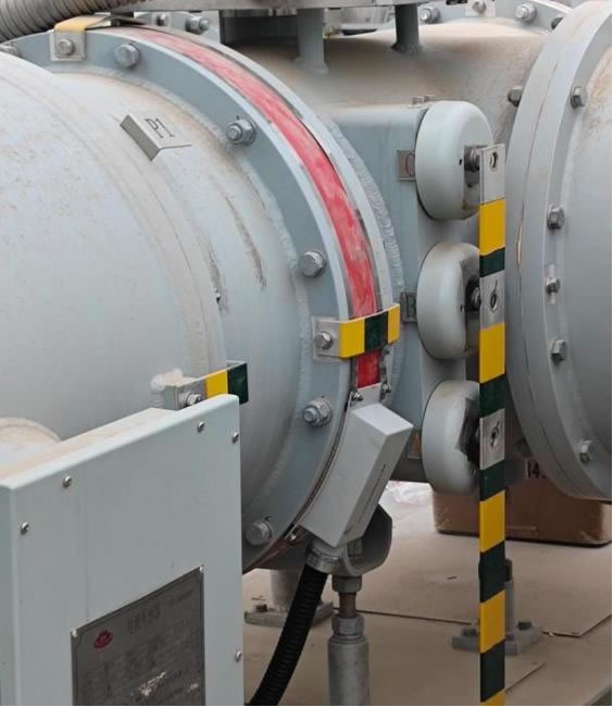
9. Installation and Deployment Considerations for GIS Environments
GIS PD monitoring systems are designed for retrofit installation on operational equipment without requiring a GIS outage. UHF sensors are mounted at designated access points on the GIS enclosure — typically at spacer flanges, inspection hatches, or dedicated sensor ports provided by the GIS manufacturer. Coaxial cables route from the sensors to the monitoring cabinet, which can be a standalone IP54-rated enclosure or a panel within the existing relay room.
Several installation practices are critical for reliable performance. Coaxial cables must maintain their minimum bend radius to prevent impedance discontinuities that degrade signal quality. Cable routes should avoid running parallel to high-voltage busbars or power cables to minimise electromagnetic coupling. All equipment grounding connections must be verified, as a poor ground can introduce noise that mimics PD signals. After physical installation, a baseline measurement should be recorded with the GIS in normal service — this baseline becomes the reference against which all future measurements are compared.
A typical installation covering a single GIS bay with 3–4 sensors, one acquisition host, and backend software can be completed in one to two weeks including commissioning, penentukuran, dan latihan pengendali.
10. How to Choose a GIS PD Monitoring System — Selection Criteria
The market includes products ranging from portable spot-check instruments to full continuous monitoring platforms. The following criteria help buyers match the right solution to their specific GIS asset.
Sensitivity and VSWR
Specify a sensor sensitivity of 5 pC or better and a VSWR of ≤ 2. These two parameters together determine real-world detection capability. A sensor with excellent stated sensitivity but a VSWR of 3 or higher loses a substantial portion of the signal before it reaches the acquisition host.
Frequency Coverage
The full 300–3 000 MHz UHF band should be covered. Some lower-cost systems operate only in a narrow sub-band, which may miss PD signatures that manifest at frequencies outside that window.
Channel Count and Expandability
Choose a system with selectable 4- or 6-channel capability and a modular architecture that allows adding sensors and channels without replacing the host unit. This protects the initial investment as the GIS installation grows.
Diagnostic Intelligence
The system must offer 3D PRPD pattern display with automated pattern matching against an expert database. Systems that report only raw signal amplitude without discharge type classification provide detection but not diagnosis — and diagnosis is what drives effective maintenance decisions.
Keserasian Protokol
Native support for the communication protocol already deployed in the substation — IEC 61850, Modbus RTU/TCP, or DNP3 — avoids the cost and reliability risk of adding external converters.
Penilaian Alam Sekitar
Sensors must be rated for the full temperature and humidity range of the site. For outdoor GIS substations in extreme climates, verify sensor operation from -40 °C hingga +85 °C and cabinet protection of at least IP54.
Vendor Track Record
Request reference installations in comparable GIS configurations and voltage classes. A vendor with a proven installed base across 110 kV, 220 kV, dan 500 kV GIS provides greater confidence in system reliability and technical support capability.
11. Soalan Lazim (Soalan Lazim)
S1: What makes UHF detection better than TEV for GIS partial discharge monitoring?
UHF detection operates in the 300–3 000 MHz range and captures electromagnetic waves propagating inside the sealed GIS enclosure, which acts as a natural shield against external noise. This gives UHF a superior signal-to-noise ratio compared to TEV, which measures transient voltage pulses on the external enclosure surface and is more exposed to ambient electromagnetic interference. UHF also provides higher sensitivity to internal defects and better capability for discharge type classification through PRPD pattern analysis. TEV remains useful as a portable screening tool, but for permanent online monitoring of GIS, UHF adalah pilihan yang unggul dari segi teknikal.
S2: Berapa banyak penderia UHF diperlukan setiap ruang GIS?
Amalan yang disyorkan ialah satu sensor bagi setiap petak GIS untuk liputan menyeluruh. Untuk susunan satu teluk biasa ini bermakna 3–4 penderia meliputi petak bas dan penamatan kabel. Ruang atau teluk kritikal dengan sejarah isu penebat mungkin memerlukan penderia tambahan pada titik lemah yang diketahui seperti sambungan pengatur jarak dan antara muka sesendal. A 4- atau hos pemerolehan 6 saluran menampung konfigurasi ini tanpa kesukaran.
S3: Bolehkah sistem membezakan antara jenis PD di dalam GIS?
ya. Sistem ini menggunakan analisis corak PRPD 3D untuk mengklasifikasikan peristiwa pelepasan kepada empat kategori: pelepasan korona daripada zarah logam bebas, pelepasan permukaan pada spacer yang tercemar, pelepasan lompang dalaman dalam penebat pepejal, and floating-potential discharge from ungrounded metallic parts. Each type produces a characteristic phase-magnitude pattern that the software matches against an expert database for automated identification.
S4: Does installation require a GIS outage?
Tidak. UHF sensors are mounted at external access points on the GIS enclosure — spacer flanges, inspection ports, or dedicated sensor windows — without opening any gas compartments. Coaxial cables are routed to the monitoring cabinet, which is installed in a nearby relay room or standalone enclosure. The entire installation, including commissioning and baseline measurement, is performed with the GIS energised and in normal service.
S5: How does the system handle false alarms in electrically noisy substations?
The GIS metallic enclosure provides natural electromagnetic shielding that inherently rejects most external interference in the UHF band. Beyond this physical advantage, the acquisition host applies frequency-domain filtering, time-domain gating, and pattern-recognition algorithms to distinguish genuine PD pulses from transient disturbances. Adjustable alarm thresholds can be tuned to the site-specific background noise level during commissioning. These combined measures typically achieve PD detection accuracy above 95 % with false alarm rates below 2 %.
S6: What SCADA protocols does the system support?
The monitoring host provides RJ45 Ethernet and RS-485 interfaces with native support for Modbus RTU, Modbus TCP, IEC 61850, dan DNP3. This covers virtually every substation automation architecture in use today and ensures that PD data — including real-time discharge magnitude, status penggera, and diagnostic codes — can be transmitted directly to the SCADA master station without external protocol converters.
S7: Apakah jangkaan pulangan pelaburan?
A single prevented GIS compartment failure — which can cost several million dollars in equipment replacement, pembaikan kecemasan, and lost revenue from extended outage — typically justifies the entire monitoring system investment. Additional ROI sources include reduced maintenance costs through the shift from time-based to condition-based inspection, extended GIS service life through early intervention, dan mengurangkan premium insurans. Most installations achieve full ROI within two to three years.
S8: Can the system be expanded after the initial installation?
ya. The modular architecture allows additional sensors to be added to new GIS compartments and connected to spare channels on the existing acquisition host. Jika semua saluran diduduki, unit hos tambahan boleh dipasang dan disambungkan ke platform perisian bahagian belakang yang sama. Berbilang ruang GIS, atau bahkan beberapa pencawang, boleh dipantau daripada antara muka perisian terpusat tunggal, menyediakan keterlihatan seluruh armada kesihatan penebat GIS.
Penafian: Maklumat yang diberikan dalam artikel ini adalah untuk tujuan pendidikan dan rujukan umum sahaja. FJINNO (www.fjinno.net) tidak membuat jaminan, tersurat atau tersirat, mengenai kesempurnaan, ketepatan, atau kesesuaian kandungan pada mana-mana projek atau pemasangan tertentu. Spesifikasi teknikal yang dirujuk di sini mewakili nilai biasa dan mungkin berbeza bergantung pada jenis GIS, penempatan sensor, dan persekitaran tapak. Keputusan kejuruteraan hendaklah sentiasa berdasarkan penilaian khusus tapak yang dijalankan oleh profesional yang berkelayakan mengikut piawaian terpakai termasuk IEC 62478, IEC 61850, dan kod grid tempatan. Nama produk pengeluar pihak ketiga ialah tanda dagangan pemilik masing-masing dan disebut untuk rujukan maklumat sahaja. FJINNO tidak akan bertanggungjawab ke atas sebarang kehilangan atau kerosakan yang timbul daripada penggunaan atau pergantungan pada maklumat ini.

Sensor suhu gentian optik, Sistem pemantauan pintar, Pengeluar gentian optik yang diedarkan di China
 |
 |
 |