 INNO 光ファイバー温度センサー ,温度監視システム.
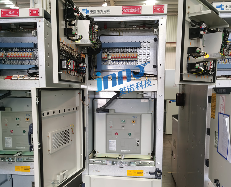
- 開閉装置温度監視システム prevent electrical fires by detecting overheating at busbar connections, サーキットブレーカーの接点, and cable terminals before failure occurs
- 蛍光光ファイバーセンサー enable safe live monitoring in high-voltage switchgear environments with complete electromagnetic immunity
- Measurement specifications: -40°C to +260°C range, ±1℃の精度, 応答時間は以下です 1 second for rapid fault detection
- 600-micron ultra-thin probes fit into confined switchgear spaces where conventional sensors cannot be installed
- Single monitoring unit supports 1-64 チャンネル with fiber lengths from 0-80 meters for flexible multi-point coverage
- Perfect electrical isolation eliminates safety risks in energized switchgear compartments up to 110kV and higher
- Superior to wireless temperature sensors, 赤外線サーモグラフィー, and thermocouple solutions for continuous monitoring
- Multi-protocol support: Modbus RTU/TCP, IEC 61850 for seamless substation automation integration
- CE-EMC, CE-LVD, and RoHS certified meeting international electrical safety standards
- Critical applications: 10kV/35kV medium voltage switchgear, リング本体, GIS変電所, load centers
- Proven prevention of busbar joint failures, circuit breaker contact degradation, and cable termination overheating
- Customizable probe shapes, mounting accessories, and communication protocols for diverse switchgear configurations
目次
- What Is a Switchgear Temperature Monitoring System and Why Is Contact Overheating the Leading Cause of Distribution System Failures?
- How Do Switchgear Online Temperature Monitoring Systems Work: Fluorescent Fiber Optic Live Measurement Principles?
- Switchgear Busbar Temperature Monitoring vs Infrared Thermography: Why Traditional Methods Cannot Meet Modern Requirements?
- Electrical Switchgear Temperature Sensor Technology Comparison: Revolutionary Advantages of Fluorescent Fiber Optic Thermometry
- The Importance of Switchgear Contact Temperature Monitoring: How Fiber Optic Sensors Prevent Fire Accidents?
- Fluorescent Fiber Optic Temperature Sensors vs Wireless Temperature Monitoring: Which Is Better for High Voltage Switchgear?
- Fluorescent Fiber Optic Sensors vs Infrared Thermal Imaging: Reliability Differences in Switchgear Applications
- Fluorescent Fiber Optic Thermometry vs GaAs Sensors: Comprehensive Comparison of High Voltage Insulation Performance
- Fiber Optic Temperature Sensors vs Thermocouples: Why Switchgear Busbars Must Use Optical Temperature Measurement?
- Switchgear Temperature Online Monitoring Anti-Interference Capability: How FFOS Handles Strong Electromagnetic Field Environments?
- 600-Micron Ultra-Fine Probe Installation Advantages: How to Achieve Precise Temperature Measurement in Confined Switchgear Spaces?
- Real-Time Temperature Monitoring Response Speed: How Fluorescent Measurement Systems Capture Switching Operation Transient Temperature Rise?
- Multi-Channel Configuration for Switchgear Temperature Monitoring Systems: How to Select 4/8/16/32 Channel Solutions?
- Medium Voltage Switchgear vs High Voltage Switchgear vs Ring Main Units: Monitoring Requirements for Different Voltage Levels
- Flexible Customization of Fluorescent Fiber Optic Temperature Measurement Devices: Probe Configuration, 繊維長, 通信プロトコル
- Switchgear Temperature Control System Integration with Substation Automation: IEC 61850 and Modbus Configuration Solutions
- 10kV Medium Voltage Switchgear Temperature Monitoring Solutions: Busbar Joint and Cable Terminal Monitoring
- 35kV High Voltage Switchgear Temperature Online Monitoring: Circuit Breaker Contact Comprehensive Monitoring Solution
- 110kV GIS Switchgear Temperature Management System: SF6 Gas Insulated Equipment Temperature Control
- Ring Main Unit Cable Joint Temperature Monitoring: Thermal Hotspot Management at Critical Distribution Network Nodes
- Switching Station Busbar Temperature Monitoring: Centralized Monitoring of Multiple Busbar Collector Systems
- Vacuum Circuit Breaker Contact Temperature Measurement: Early Warning for Contact Wear and Resistance
- Load Switch Temperature Monitoring System: Dynamic Tracking of Temperature Rise During Opening and Closing Operations
- Disconnector Blade Temperature Monitoring: Real-Time Detection of Poor Blade Contact
- Cable Joint Temperature Measurement: Distributed Monitoring in Cable Tunnels and Shafts
- Busbar Bridge Temperature Monitoring: Thermal Management of Critical Busbar Connection Points in Substations
- Industrial Distribution Panel Temperature Monitoring: Intelligent Retrofit of Factory Workshop Distribution Systems
- Data Center Electrical Distribution Temperature Monitoring: Hotspot Management for High-Density IT Load Distribution
- International Standards for Switchgear Temperature Monitoring: IEC 62271 and GB 3906 Technical Requirements Explained
- Electrical Equipment Temperature Sensor CE-EMC, CE-LVD, RoHS Certification: 品質保証体制
- Switchgear Condition Monitoring System Certification Requirements: How to Ensure Monitoring Equipment Complies with Grid Standards?
- Urban Metro 35kV Switching Station Temperature Monitoring Case: 24-Channel System Fire Prevention Early Warning Practice
- Industrial Park 10kV Switchgear Monitoring Project: How Fluorescent Fiber Optic Sensors Detect Early Overheating?
- Data Center Electrical Distribution System Temperature Management Case: Reliability Verification in High-Availability Environments
- Switchgear Temperature Sensor Technology Comparison Table: Fluorescent Fiber Optic vs Wireless vs Infrared vs Thermocouple
- Switchgear Temperature Monitoring System Selection Guide: Key Parameters and Decision Factors
- トップ 10 Best Switchgear Fiber Optic Temperature Monitoring System Manufacturers Ranking
- Switchgear Temperature Monitoring System FAQ: 15 Most Common Technical Questions Answered
- How to Obtain Customized Switchgear Temperature Monitoring Solutions and Professional Technical Support?
1. とは何ですか 開閉装置温度監視システム and Why Is Contact Overheating the Leading Cause of Distribution System Failures?
あ 開閉装置温度監視システム is a specialized safety device designed to continuously measure thermal conditions at critical electrical connections within medium and high-voltage switchgear equipment. These systems protect power distribution infrastructure by detecting abnormal temperature rises that indicate developing failures before they escalate into catastrophic events.
The Critical Nature of Switchgear Thermal Management
Electrical connection failures account for approximately 60-70% 全部の switchgear-related incidents, with most caused by progressive overheating at busbar joints, サーキットブレーカーの接点, およびケーブル終端. Unlike sudden insulation breakdown, thermal failures develop gradually over months or years as contact surfaces oxidize, mechanical pressure loosens, or current loading increases.
開閉装置温度監視システム を使用して 蛍光光ファイバーセンサー detect these developing problems through temperature signatures—typically showing 10-30°C temperature rise above normal operating conditions before visible damage occurs. This early warning enables preventive maintenance that avoids unplanned outages, 機器の損傷, and potential arc flash incidents.
2. How Do Switchgear Online Temperature Monitoring Systems Work: Fluorescent Fiber Optic Live Measurement Principles?

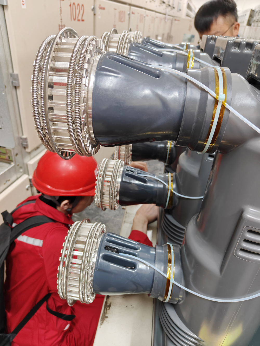
Fluorescent fiber optic temperature measurement technology enables safe monitoring of energized switchgear components by placing 600-micron diameter glass fiber probes directly on busbars, 連絡先, and terminals without creating any electrical safety hazards.
Fluorescence Lifetime Measurement in Switchgear Applications
The sensor probe tip contains rare-earth phosphor material that emits fluorescence when excited by LED pulses transmitted through the optical fiber. The decay rate of this fluorescence varies precisely with temperature. の 光ファイバー温度トランスミッター measures this decay time (fluorescence lifetime) to calculate temperature with ±1°C accuracy across the -40°C to +260°C range.
Because this measurement relies on time-domain analysis rather than light intensity, it remains immune to fiber bending, dust accumulation on connections, and aging effects that compromise other optical sensing methods. シングル multi-channel monitoring unit can support 1-64 sensor points throughout a switchgear lineup, with fiber lengths extending up to 80 meters from measurement locations to the control panel.
3. Switchgear Busbar Temperature Monitoring vs Infrared Thermography: Why Traditional Methods Cannot Meet Modern Requirements?

Infrared thermal imaging has served as the standard method for switchgear temperature assessment for decades. Maintenance personnel perform periodic thermographic surveys—typically annually or semi-annually—to identify hot spots through handheld IR cameras or viewing windows.
Critical Limitations of Periodic Infrared Inspection
Infrared surveys provide only snapshot assessments during inspection intervals. Problems developing between inspections go undetected until the next scheduled survey, potentially allowing critical failures to progress unnoticed for months. さらに, IR measurement accuracy depends on emissivity settings, viewing angle, and environmental reflections—all factors that introduce measurement uncertainty.
Continuous switchgear temperature monitoring と 蛍光光ファイバーセンサー eliminates these limitations by providing 24/7 real-time measurement at fixed critical points. The system detects temperature changes within seconds, enabling immediate response to developing problems regardless of when they occur. Direct contact measurement also provides superior accuracy compared to IR radiation measurement through viewing ports.
4. Electrical Switchgear Temperature Sensor Technology Comparison: Revolutionary Advantages of Fluorescent Fiber Optic Thermometry
The evolution from electrical to optical temperature sensing represents a paradigm shift for 開閉装置の監視. Traditional electrical sensors—thermocouples and RTDs—create safety hazards in high-voltage environments, while wireless sensors suffer from battery maintenance requirements and signal reliability issues.
Why Optical Sensing Changed Switchgear Monitoring
蛍光光ファイバー温度センサー eliminate safety concerns through completely non-conductive construction. Glass fibers carry optical signals that cannot conduct electricity, allowing sensor installation directly on energized busbars at thousands of volts potential without creating shock hazards or ground faults.
The all-dielectric nature of 光ファイバーセンサー also provides perfect electromagnetic immunity—critical in switchgear environments where current interruption and fault conditions generate intense electromagnetic transients that destroy conventional sensors or cause false alarms in wireless systems.
5. The Importance of Switchgear Contact Temperature Monitoring: How Fiber Optic Sensors Prevent Fire Accidents?
Electrical fires in switchgear facilities cause devastating consequences: 設備破壊, extended outages affecting thousands of customers, injury risks to personnel, and potential facility loss. Investigation of switchgear fire incidents consistently identifies overheating electrical connections as the initiating event.
The Progressive Nature of Connection Failures
Busbar joint overheating typically follows a predictable progression: initial temperature rise of 5-10°C above ambient goes unnoticed, oxidation accelerates at elevated temperature increasing contact resistance, higher resistance generates more heat in a positive feedback loop, and finally catastrophic failure occurs when insulation ignites or metal melts.
開閉装置温度監視システム と 蛍光光ファイバーセンサー interrupt this failure progression by detecting abnormal temperatures during the early stages when corrective action is straightforward. Tightening a loose connection or cleaning oxidized contact surfaces during scheduled maintenance prevents the progression to catastrophic failure.
6. 蛍光ファイバー光温度センサー vs Wireless Temperature Monitoring: Which Is Better for High Voltage Switchgear?

Wireless temperature monitoring systems have gained popularity for switchgear applications due to installation simplicity—battery-powered sensors attach to busbars and transmit data via radio to receivers. しかし, field experience reveals significant limitations compared to 光ファイバー監視ソリューション.
Critical Comparison Factors
| パラメータ | 蛍光光ファイバー | ワイヤレスセンサー |
|---|---|---|
| Power Source | No power required at sensor (光学的) | 電池交換ごと 2-5 年 |
| Signal Reliability | 100% 信頼性のある (physical fiber connection) | Can be blocked by metal enclosures |
| EMI耐性 | 完了 (光信号) | RF interference during switching operations |
| 応答時間 | <1 2番 | 5-60 秒 (depends on transmission interval) |
| メンテナンス | Zero maintenance for 20+ 年 | Regular battery replacement required |
| Long-Term Cost | より低い (no consumables) | より高い (battery costs + 労働) |
クリティカルな場合 高圧開閉装置監視, the maintenance-free operation and guaranteed signal reliability of 蛍光光ファイバーシステム provide superior long-term value despite potentially higher initial costs.
7. Fluorescent Fiber Optic Sensors vs Infrared Thermal Imaging: Reliability Differences in Switchgear Applications
While infrared thermography provides valuable diagnostic information during periodic inspections, it cannot match the continuous monitoring capability of permanently installed 光ファイバー温度センサー.
Continuous vs Periodic Monitoring
基本的な利点は、 蛍光光ファイバー温度監視 is continuous data collection. Temperature trends reveal developing problems through gradual increases over days or weeks—patterns invisible to periodic snapshots. さらに, transient overheating during peak loading or switching operations may occur between inspection intervals, escaping detection by quarterly or annual IR surveys.
Fixed-point fiber optic sensors also eliminate the viewing angle and emissivity uncertainties inherent in IR measurements. Direct contact measurement provides consistent, repeatable accuracy regardless of surface conditions or measurement technique.
8. 蛍光光ファイバー温度計 vs GaAs Sensors: Comprehensive Comparison of High Voltage Insulation Performance

ガリウムヒ素 (GaAs) semiconductor sensors represent another optical temperature measurement technology occasionally used in switchgear applications. しかし, 蛍光光ファイバーセンサー offer distinct advantages for long-term switchgear monitoring.
Stability and Reliability Comparison
GaAs sensors can experience gradual accuracy drift due to radiation exposure from corona discharge in high-voltage switchgear environments. Long-term installations show potential drift of 1-2°C over 7-10 年. 対照的に, the stable rare-earth phosphors used in 蛍光光ファイバー温度センサー maintain calibration indefinitely—field installations demonstrate zero drift over 15+ 年間の継続稼働.
さらに, GaAs technology typically requires more complex signal processing and offers narrower temperature ranges compared to the -40°C to +260°C capability of 蛍光ベースのシステム, limiting applicability in extreme conditions.
9. Fiber Optic Temperature Sensors vs Thermocouples: Why Switchgear Busbars Must Use Optical Temperature Measurement?
Thermocouples have traditionally served as the lowest-cost temperature sensors. しかし, their metallic construction creates fundamental safety issues for switchgear busbar temperature monitoring.
Safety and Accuracy Limitations
Installing thermocouples on energized busbars creates electrical connections between high-voltage components and grounded monitoring equipment. This necessitates expensive isolation amplifiers that add cost, 複雑, and failure points. Even with isolation, the metallic thermocouple wires act as antennas that pick up electromagnetic interference from switchgear currents, corrupting the millivolt-level measurement signals.
光ファイバー温度センサー eliminate all these problems through non-conductive glass construction. The complete absence of metallic components makes them inherently safe for high-voltage installations while delivering interference-free measurement accuracy.
10. Switchgear Temperature Online Monitoring Anti-Interference Capability: How FFOS Handles Strong Electromagnetic Field Environments?
Switchgear compartments contain some of the harshest electromagnetic environments in electrical systems. Normal operation generates fields from hundreds of amperes of continuous current, while switching operations and fault conditions create transients that can induce thousands of volts in nearby conductors.
Perfect EMI Immunity Through Optical Technology
溝 (蛍光光ファイバーセンサー) technology achieves complete electromagnetic immunity because light signals do not interact with electric or magnetic fields. While electrical sensors require extensive shielding, フィルタリング, and isolation to achieve even marginal noise immunity, 光ファイバー温度監視システム operate flawlessly in the most intense electromagnetic environments.
This immunity extends to transient events that destroy conventional sensors. Lightning surges entering switchgear through power connections, switching transients from circuit breaker operations, and electromagnetic pulses from nearby fault currents have zero effect on 光学式温度測定, ensuring continuous monitoring during the very events when thermal data is most critical.
11. 600-Micron Ultra-Fine Probe Installation Advantages: How to Achieve Precise Temperature Measurement in Confined Switchgear Spaces?
Switchgear design prioritizes compact construction to minimize substation footprint and material costs. This leaves minimal space for instrumentation—particularly at critical measurement points like busbar joints buried deep within compartments.
Unique Installation Flexibility
The 600-micron (0.6mm) diameter of 蛍光光ファイバーセンサー probes enables installations impossible with conventional 3-6mm diameter sensors. The ultra-thin fiber routes through narrow gaps between insulating barriers, wraps around busbar elbows, and navigates tortuous paths to reach measurement locations.
This small diameter also minimizes the probe’s thermal mass, achieving sub-second response times critical for detecting rapid temperature changes during switching operations or overload conditions. The smooth glass surface prevents sharp edges that could damage insulation materials during installation or thermal expansion.
12. Real-Time Temperature Monitoring Response Speed: How Fluorescent Measurement Systems Capture Switching Operation Transient Temperature Rise?
Electrical switching operations—circuit breaker opening/closing, 荷重移動, and motor starting—create transient current surges that cause rapid localized heating at connection points with elevated resistance.
Fast Response for Critical Event Capture
蛍光光ファイバー温度センサー 以下の応答時間を達成します 1 2番, enabling capture of these transient thermal events. This fast response proves critical for identifying intermittent connection problems that only manifest during switching operations—issues that slower sensors (5-10 second response) would completely miss.
The combination of fast response and continuous monitoring allows switchgear temperature systems to track thermal cycling patterns that contribute to connection degradation over time, enabling predictive maintenance strategies impossible with periodic inspection methods.
13. Multi-Channel Configuration for Switchgear Temperature Monitoring Systems: How to Select 4/8/16/32 Channel Solutions?
Optimal channel configuration depends on switchgear complexity, 臨界度, と予算の制約. The scalable architecture of fluorescent fiber optic temperature transmitters accommodates systems from minimal 4-channel installations to comprehensive 32-channel monitoring networks.
Channel Count Guidelines by Application
4-8 チャネルシステム
Suitable for simple switchgear lineups monitoring highest-risk locations: main busbar joints, incomer circuit breaker contacts, and critical feeder cable terminations. This economical configuration provides essential protection for medium-criticality facilities.
16-24 チャネルシステム
Standard for complex switchgear installations requiring comprehensive coverage. Multiple sensors per busbar section, individual circuit breaker monitoring, and cable compartment coverage enable detailed thermal mapping of entire switchgear lineups.
32+ チャネルシステム
Reserved for critical facilities (病院, データセンター, 産業プロセス) where switchgear failure consequences justify maximum monitoring investment. Dense sensor arrays enable predictive maintenance programs and detailed thermal analysis.
14. Medium Voltage Switchgear vs High Voltage Switchgear vs Ring Main Units: Monitoring Requirements for Different Voltage Levels

Switchgear monitoring complexity varies significantly across voltage classifications. Understanding the relationship between equipment characteristics and thermal risks ensures appropriate 温度監視システム deployment without over-specification or inadequate protection.
10kV Medium Voltage Switchgear
Distribution switchgear operating at 10kV (or 11kV/13.8kV internationally) represents the most common application for 開閉装置の温度監視. These installations typically feature air-insulated construction with exposed busbar connections accessible for sensor installation. Critical monitoring points include main busbar joints (3-6 センサー), circuit breaker primary contacts (2 sensors per breaker), and outgoing cable terminations (1 sensor per critical feeder). アン 8 に 16 channel system provides adequate coverage for typical 10kV switchgear lineups.
35kV High Voltage Switchgear
Switchgear at 35kV voltage levels employs more sophisticated insulation systems with increased clearances and often SF6 gas insulation in critical sections. Monitoring requirements expand to include disconnector blade contacts, instrument transformer connections, and surge arrester terminals in addition to standard busbar and breaker monitoring. 16 に 24 channel monitoring systems serve typical 35kV installations, with higher counts for complex substation configurations.
リング本体 (RMU)
Ring main units form critical nodes in urban distribution networks where multiple cable circuits interconnect in compact enclosures. The high-density cable terminations in confined spaces create elevated thermal stress. Specialized RMU monitoring focuses on cable joint temperatures and load break switch contacts, typically requiring 6-12 measurement channels depending on circuit count and criticality.
15. Flexible Customization of Fluorescent Fiber Optic Temperature Measurement Devices: Probe Configuration, 繊維長, 通信プロトコル
Switchgear configurations vary dramatically across manufacturers, 電圧レベル, および申請要件. 主要な 光ファイバー温度監視システム suppliers offer extensive customization options that adapt to specific installation needs.
Probe Configuration Options
Fiber optic sensor probes can be customized with different sensing tip geometries for various mounting scenarios: surface-mount configurations for flat busbar attachment, wraparound designs for cylindrical conductors, and insertion probes for penetrating cable terminations. Mounting accessories include spring clips for tool-free installation, threaded studs for permanent attachment, and magnetic bases for temporary diagnostic applications.
Fiber Length Customization
Standard fiber lengths from 2-10 meters suit compact switchgear rooms, while extended 20-40 meter fibers serve large substations with remote control buildings. の 0-80 meter capability of 蛍光寿命測定 maintains full accuracy across the entire range since time-domain signals remain immune to fiber attenuation.
Communication Protocol Flexibility
モダンな switchgear monitoring systems 複数の産業用プロトコルをサポート: Modbus RTU over RS485 for local SCADA connections, Modbus TCP for Ethernet integration, IEC 61850 for substation automation compliance, and 4-20mA analog outputs for legacy control systems. Custom protocol implementations serve equipment manufacturers integrating monitoring into switchgear designs.
16. Switchgear Temperature Control System Integration with Substation Automation: IEC 61850 and Modbus Configuration Solutions
効果的 開閉装置の温度監視 requires seamless integration with existing substation automation and building management systems for alarm handling, data trending, and maintenance scheduling.
IEC 61850 Substation Communication
International utilities increasingly mandate IEC 61850 compliance for all intelligent electronic devices (IED) 変電所内. 高度な 光ファイバー温度監視システム implement IEC 61850-7-4 logical nodes (STMP for temperature measurement) with full MMS server functionality and GOOSE messaging for fast peer-to-peer alarm transmission. This enables plug-and-play integration with substation automation platforms.
Modbus RTU/TCP Implementation
Modbus remains the dominant protocol for industrial facilities and commercial buildings. Switchgear temperature transmitters implement standard Modbus register mapping with all temperature channels, alarm states, and diagnostic data accessible through function codes 03/04. RS485 serial networks support multi-drop configurations with up to 247 デバイス, while Modbus TCP enables direct connection to Ethernet-based SCADA systems.
17. 10kV Medium Voltage Switchgear Temperature Monitoring Solutions: Busbar Joint and Cable Terminal Monitoring
Medium voltage switchgear serving commercial buildings, 産業施設, and distribution substations requires cost-effective monitoring that balances protection with economic constraints. アン 8 に 12 channel fluorescent fiber optic system provides comprehensive coverage for typical 10kV installations.
Optimal Sensor Placement Strategy
The standard configuration focuses on highest-risk failure points: main busbar joints connecting switchgear sections (通常 4-6 sensors for three-phase systems), circuit breaker moving and fixed contacts on critical feeders (2 sensors per breaker), and outgoing cable terminations supplying important loads (1 sensor per critical cable). Additional channels monitor transformer primary connections and bus-tie breaker contacts in double-bus configurations.
Alarm Configuration and Response
の 温度監視トランスミッター provides configurable alarm thresholds: warning level at 10-15°C above normal operating temperature (typically 60-70°C absolute) and critical alarm at 20-30°C differential (80-90絶対℃). Relay outputs trigger local visual/audible alarms and integrate with facility management systems for automated work order generation and maintenance scheduling.
18. 35kV High Voltage Switchgear Temperature Online Monitoring: Circuit Breaker Contact Comprehensive Monitoring Solution
High voltage switchgear installations in primary substations require more extensive monitoring due to higher failure consequences and equipment criticality. 16 に 24 channel systems deliver the detailed thermal visibility demanded for these critical assets.
Circuit Breaker Monitoring Strategy
Vacuum circuit breakers in 35kV service experience contact erosion from repeated interruption duty. Contact temperature monitoring provides early warning of degradation before contact resistance increases to dangerous levels. Sensors placed on both moving and fixed contacts of each pole reveal asymmetrical wear patterns indicating required maintenance. Temperature differentials between phases greater than 10°C flag mechanical misalignment or unequal contact pressure requiring adjustment.
Busbar and Disconnector Coverage
The expanded clearances in 35kV switchgear create longer busbar spans with more bolted joints—each a potential failure point. 包括的な光ファイバー監視 covers all major bolted connections plus disconnector blade contacts that rarely carry load but can develop problems from oxidation during extended idle periods. The 600-micron fiber diameter enables routing through insulating barriers to reach measurement points without compromising electrical clearances.
19. 110kV GIS Switchgear Temperature Management System: SF6 Gas Insulated Equipment Temperature Control
ガス絶縁開閉装置 (GIS) installations use SF6 gas insulation to achieve compact 110kV+ substations in confined spaces. The sealed enclosures prevent visual inspection and limit access for temperature monitoring, 作る internal temperature sensors essential for thermal management.
GIS-Specific Monitoring Challenges
GIS busbar connections and circuit breaker contacts operate inside pressurized SF6 enclosures with no external visibility. Traditional IR inspection is impossible, making permanently installed 光ファイバー温度センサー the only viable continuous monitoring solution. Sensors integrate during GIS manufacturing, with fibers routed through hermetic seals to external monitoring equipment.
全誘電体構造 蛍光光ファイバーセンサー is critical for GIS applications—any metallic sensor components would create partial discharge sites that degrade SF6 insulation. The optical measurement principle ensures zero electromagnetic emissions that could interfere with sensitive protection and control equipment adjacent to GIS installations.
20. Ring Main Unit Cable Joint Temperature Monitoring: Thermal Hotspot Management at Critical Distribution Network Nodes
Ring main units (RMU) in urban distribution networks represent single points of failure where multiple cable circuits interconnect in compact enclosures. Joint failures cause cascading outages affecting numerous customers, 作る preventive temperature monitoring 特に貴重な.
Cable Joint Monitoring Configuration
Typical RMU installations include 3-6 cable circuits with multiple joints per circuit (incoming, outgoing, and loop connections). 光ファイバー温度センサー monitor each joint’s hottest point—typically the compression lug contact area where cable conductors terminate on busbar studs. The 600-micron probe diameter fits within cable termination boots without compromising insulation integrity.
Early Failure Detection
Cable joint failures typically progress over 6-18 months as contact resistance gradually increases due to oxidation or mechanical loosening. Continuous temperature trending reveals these developing problems through slowly rising baseline temperatures and increasing temperature differentials between joints. Early detection enables scheduled maintenance during planned outages rather than emergency response to failed cables during peak loading.
21. Switching Station Busbar Temperature Monitoring: Centralized Monitoring of Multiple Busbar Collector Systems
Large switching stations and industrial facilities often employ complex busbar systems with multiple sections, bus-ties, and transfer schemes. Comprehensive temperature monitoring provides operators with thermal visibility across entire busbar networks.
Multi-Section Busbar Coverage
Switching stations may contain 10-20+ busbar sections with dozens of bolted joints connecting segments. 32 channel fluorescent fiber optic systems enable monitoring all major joints plus critical feeder connections. Network architecture allows multiple transmitters to share data via Modbus TCP, providing unified dashboard displays showing thermal status across the entire facility.
Trending and analysis software identifies gradual temperature increases indicating developing joint problems and compares temperatures across similar connections to flag outliers. This predictive maintenance capability prevents failures and optimizes maintenance resource allocation by prioritizing work based on actual thermal condition rather than time-based schedules.
22. Vacuum Circuit Breaker Contact Temperature Measurement: Early Warning for Contact Wear and Resistance
Vacuum circuit breakers dominate medium voltage applications due to their maintenance-free operation and long electrical life. しかし, contact erosion from repeated switching eventually requires replacement. Contact temperature monitoring enables condition-based maintenance timing.
Contact Erosion Detection
New vacuum interrupter contacts operate at temperatures only 5-10°C above conductor temperature under rated current. As contacts erode from switching duty, contact resistance increases and temperature rises. A 20-30°C differential above normal operating temperature indicates significant erosion requiring interrupter replacement during the next maintenance window. これ predictive maintenance approach prevents unexpected failures while maximizing interrupter utilization.
23. Load Switch Temperature Monitoring System: Dynamic Tracking of Temperature Rise During Opening and Closing Operations
Load break switches in distribution systems perform frequent switching operations that create transient arcing and contact heating. Fast-response temperature monitoring tracks these thermal cycles to assess switch condition.
Switching Cycle Temperature Analysis
The sub-second response time of 蛍光光ファイバーセンサー captures temperature spikes during switching operations. Healthy load switches show temperature increases of 5-15°C during operation, returning to baseline within 30-60 秒. Degraded switch contacts exhibit higher peak temperatures and slower cooling, indicating contact wear or contamination requiring cleaning or replacement.
Accumulated thermal cycle data enables lifetime prediction based on actual thermal stress rather than simple operation counting. This sophisticated approach optimizes switch replacement timing and prevents premature failures in heavily cycled switches.
24. Disconnector Blade Temperature Monitoring: Real-Time Detection of Poor Blade Contact
Disconnector switches (アイソレーター) operate infrequently but must maintain low contact resistance during extended periods of continuous current carrying. Contact degradation from oxidation or mechanical wear goes undetected without continuous temperature monitoring.
Contact Pressure Verification
光ファイバー温度センサー installed on disconnector blade contacts provide immediate indication of contact problems through elevated temperature. Properly adjusted disconnector contacts operate within 5°C of busbar temperature, while poor contact shows 15-40°C temperature rise. This thermal signature enables maintenance prioritization—severely overheated disconnectors require immediate attention while moderate temperature rises can wait for scheduled outages.
25. Cable Joint Temperature Measurement: Distributed Monitoring in Cable Tunnels and Shafts
Underground cable systems in urban areas and industrial facilities contain numerous joints where cable sections connect. These joints represent potential failure points, particularly in heavily loaded circuits. Strategic temperature monitoring focuses on highest-risk locations.
Cable Joint Failure Prevention
Cable joint failures typically result from poor installation workmanship or degradation of compression connections over time. 蛍光光ファイバーモニタリング of critical joints (伝送ケーブル, main feeders to critical loads, difficult-to-access locations) provides early warning through temperature trending. の 0-80 meter fiber length capability enables monitoring joints throughout cable routes from a single transmitter location in an accessible manhole or vault.
26. Busbar Bridge Temperature Monitoring: Thermal Management of Critical Busbar Connection Points in Substations
Busbar bridges connecting switchgear sections, 変圧器, and isolated bus structures contain high-current bolted connections susceptible to overheating from thermal cycling and mechanical vibration. Strategic sensor placement prevents bridge failures.
High-Current Connection Monitoring
Busbar bridges often carry full substation load current through relatively small contact areas, creating concentrated heating if connections degrade. 光ファイバー温度センサー positioned at each bolted joint on bridges detect developing problems before they progress to failure. The electrical isolation of optical sensing enables safe monitoring of connections at different voltage potentials without isolation barriers.
27. Industrial Distribution Panel Temperature Monitoring: Intelligent Retrofit of Factory Workshop Distribution Systems
Manufacturing facilities rely on extensive distribution panel systems supplying production equipment. Aging installations with decades of service benefit from retrofit temperature monitoring that extends equipment life and prevents production disruptions.
Retrofit Installation Strategies
The compact 600-micron fiber diameter enables non-invasive monitoring retrofits on existing industrial switchgear. Fibers route through existing cable entry points or small-diameter holes drilled in enclosure walls, with sensors attached to critical connections using spring clips that install without de-energizing equipment. This approach minimizes installation costs and production impact while delivering comprehensive thermal protection.
28. Data Center Electrical Distribution Temperature Monitoring: Hotspot Management for High-Density IT Load Distribution
Data centers represent mission-critical facilities where electrical failures cause catastrophic business impacts. The high-density power distribution systems (often 2-4 MW per hall) justify comprehensive 温度監視 for maximum reliability.
Tier III/IV Reliability Requirements
Uptime Institute Tier III and IV certifications require redundant power paths with comprehensive monitoring and automated fault detection. マルチチャンネル光ファイバー温度監視 on all main distribution switchgear, transfer switches, and critical branch circuits provides the continuous thermal visibility required for certification and operations. Integration with building management systems enables automated load transfer away from overheating components before failure occurs, maintaining 99.99%+ availability targets.
29. International Standards for Switchgear Temperature Monitoring: IEC 62271 and GB 3906 Technical Requirements Explained
Global standards define design, テスト, and performance requirements for switchgear equipment and associated monitoring systems, ensuring safety and reliability across different manufacturers.
IEC 62271 Switchgear Standards
The International Electrotechnical Commission standard IEC 62271 series covers high-voltage switchgear and controlgear, specifying temperature rise limits for various components. IEC 62271-1 defines maximum temperature rises: 105K for bare copper connections under normal service conditions. 開閉装置温度監視システム must provide sufficient accuracy to detect when equipment approaches these limits, enabling protective action before damage occurs.
GB 3906 中国の国家規格
GB 3906 specifies technical requirements for 3.6-40.5kV AC metal-enclosed switchgear in China, including provisions for temperature monitoring capabilities. The standard recognizes continuous temperature monitoring as preferred practice for critical installations, particularly where equipment operates near rated capacity or in harsh environments.
30. Electrical Equipment Temperature Sensor CE-EMC, CE-LVD, RoHS Certification: 品質保証体制
International certifications demonstrate that switchgear monitoring equipment meets rigorous electromagnetic compatibility, 電気の安全性, and environmental standards required for global markets.
CE-EMC certification verifies electromagnetic compatibility—both immunity to external interference and low emissions. CE-LVD (Low Voltage Directive) confirms electrical safety of monitoring units, その間 RoHS compliance ensures environmental responsibility through restriction of hazardous substances. These certifications are mandatory for European markets and increasingly specified by utilities and industrial facilities worldwide.
31. Switchgear Condition Monitoring System Certification Requirements: How to Ensure Monitoring Equipment Complies with Grid Standards?
Utility interconnection standards and facility safety codes increasingly mandate specific performance criteria for monitoring equipment installed on electrical distribution assets.
Many utilities require IEC 61850 コンプライアンス for substation monitoring equipment, while industrial facilities may specify UL 508A or CSA C22.2 certification for control panel equipment. 品質 蛍光光ファイバー温度監視システム maintain comprehensive certification portfolios covering diverse requirements, simplifying compliance verification during procurement.
32. Urban Metro 35kV Switching Station Temperature Monitoring Case: 24-Channel System Fire Prevention Early Warning Practice
A metropolitan rail system deployed 24-channel fluorescent fiber optic monitoring across their 35kV traction power substations following several overheating incidents that caused service disruptions.
実施結果
Installation covered all main busbar joints, サーキットブレーカーの接点, and cable terminations in each switching station. 6か月以内, the system detected developing failures at three locations: a loose busbar connection showing 35°C temperature rise, degraded circuit breaker contacts with 28°C differential, and a cable termination with progressive oxidation. All repairs occurred during scheduled maintenance windows, preventing unplanned outages estimated at $1.2 million in revenue loss and customer compensation.
33. Industrial Park 10kV Switchgear Monitoring Project: How Fluorescent Fiber Optic Sensors Detect Early Overheating?
A manufacturing complex installed 16-channel monitoring on their main 10kV distribution switchgear supplying production lines operating 24/7 with high failure costs.
温度傾向を分析すると、2 つのバスバー接続部で 4 か月にわたって徐々に上昇し、通常の 45°C から 68°C まで上昇していることがわかりました。. 計画的シャットダウン中の熱画像検査により、両方の接続部の酸化が確認されました. 洗浄と締め直しにより正常な温度に戻りました. 施設は、この早期発見により救われたと推定しました $450,000 事後保全アプローチと比較して、計画外の停止による潜在的な生産損失の削減.
34. Data Center Electrical Distribution System Temperature Management Case: Reliability Verification in High-Availability Environments
包括的に展開された Tier III データセンター 光ファイバー温度監視 すべての重要な配電機器の一部として 99.982% 稼働時間のコミットメント.
3年以上の運用実績, の 32-チャンネル監視システム 継続的な熱可視性を提供し、機器の故障前に 2 回の予防的なメンテナンス介入を可能にします. 投資は以下の期間で元が取れました 18 months through avoided downtime. この施設は、電気インフラの信頼性に完全な自信を持っていると報告しています, 熱的安全性を考慮せずに積極的なサーバー密度の増加を可能にする.
35. Switchgear Temperature Sensor Technology Comparison Table: Fluorescent Fiber Optic vs Wireless vs Infrared vs Thermocouple
| パラメータ | 蛍光光ファイバー | ワイヤレスセンサー | 赤外線サーモグラフィー | 熱電対 |
|---|---|---|---|---|
| 監視タイプ | 継続的 24/7 | 継続的 (定期送信) | Periodic inspection only | 継続的 |
| 正確さ | ±1℃ | ±2~3℃ | ±2~5℃ (放射率依存) | ±2℃ |
| 応答時間 | <1 2番 | 5-60 秒 | 該当なし (マニュアル) | 2-5 秒 |
| EMI耐性 | 完了 | 適度 (RF interference) | 該当なし | 貧しい |
| メンテナンス | ゼロ (20+ 年) | 電池交換 (2-5 年) | 定期的な調査が必要 | 低い |
| 設置の安全性 | ライブ機器でも安全 | ライブ機器でも安全 | パネルへのアクセスが必要です | 電源を切る必要があります |
| 最適な用途 | 重要な開閉装置 | 一時的な監視 | 定期調査 | 低電圧アプリケーション |
36. Switchgear Temperature Monitoring System Selection Guide: Key Parameters and Decision Factors
最適なものを選択する 開閉装置温度監視システム 技術要件の評価が必要, 施設の重要度, 特定のアプリケーションのニーズに合わせた予算の制約.
Critical Selection Criteria
1. 電圧レベルと絶縁要件: センサーの電気絶縁が開閉装置の電圧クラスを満たしていることを確認する. 蛍光光ファイバーセンサーは、全誘電体構造により無制限の電圧機能を提供します.
2. Number of Monitoring Points: バスバー接続部を含む重要な測定位置をカウント, サーキットブレーカーの接点, ケーブル終端, および断路器スイッチ. Add 10-15% 余力.
3. インストールの制約: センサーの配線に利用可能なスペースを評価する. ファイバー径600ミクロンにより、従来のセンサーでは不可能だった狭い場所への設置が可能.
4. Communication Requirements: Identify required protocols (Modbus, IEC 61850, DNP3) and verify compatibility with existing SCADA or building management systems.
5. 環境条件: Consider ambient temperature extremes, 湿度, ほこり, と振動. Confirm transmitter environmental ratings match installation location conditions.
37. トップ 10 Best Switchgear Fiber Optic Temperature Monitoring System Manufacturers Ranking
🏆 #1 フジノ (福州イノベーション電子科学&テック株式会社, 株式会社. )

🥈 #2 華光天瑞 (Beijing Huaguang Tianrui Optoelectronic Technology Co., 株式会社)

| 設立 | 2016 |
| 本部 | 福建省, 中国 |
| 製品カテゴリー | 蛍光光ファイバーセンサー, distributed temperature monitoring systems, 電力設備の監視 |
| Market Focus | Chinese utility market, State Grid projects |
#3 ワイドマン エレクトリカル テクノロジー AG
| 設立 | 1877 (monitoring division: 2000s) |
| 本部 | ラッパースウィル, スイス |
| 製品カテゴリー | 変圧器監視システム, 光ファイバーセンサー, ブッシング監視, DGA analysis |
| Market Focus | European utilities, premium transformer monitoring solutions |
#4 Qualitrol Corporation (Fortive)
| 設立 | 1945 (acquired Neoptix 2018) |
| 本部 | フェアポート, ニューヨーク, アメリカ合衆国 |
| 製品カテゴリー | 光ファイバー温度センサー (fluorescent and GaAs), 変圧器モニター, switchgear sensors |
| Market Focus | North American utilities, IEC 61850 integration expertise |
#5 AMETEK / LumaSense テクノロジー
| 設立 | 1930 (ルマセンス: 2005) |
| 本部 | Santa Clara, California, アメリカ合衆国 |
| 製品カテゴリー | Multiple optical temperature technologies, 赤外線センサー, 産業プロセスの監視 |
| Market Focus | 産業用途, some power utility presence |
#6 Siemens Energy AG
| 設立 | 1847 (Energy spun off 2020) |
| 本部 | Munich, ドイツ |
| 製品カテゴリー | Integrated switchgear monitoring, asset health management systems, 変電所の自動化 |
| Market Focus | Global utilities, integrated monitoring solutions with switchgear equipment |
#7 ABB Ltd
| 設立 | 1988 (from merger) |
| 本部 | Zurich, スイス |
| 製品カテゴリー | Switchgear condition monitoring, デジタル変電所, asset health analytics |
| Market Focus | Global utilities, focus on digital transformation and IIoT integration |
#8 Schneider Electric SE
| 設立 | 1836 |
| 本部 | Rueil-Malmaison, フランス |
| 製品カテゴリー | Medium voltage monitoring systems, EcoStruxure プラットフォーム, wireless and fiber optic sensors |
| Market Focus | Commercial buildings, 産業施設, データセンター |
#9 GE グリッド ソリューション (GE バーノバ)
| 設立 | 1892 (Grid Solutions restructured 2023) |
| 本部 | Boston, Massachusetts, アメリカ合衆国 |
| 製品カテゴリー | Asset performance management, 開閉装置の監視, grid optimization software |
| Market Focus | Large utilities, transmission and distribution infrastructure |
#10 Eaton Corporation
| 設立 | 1911 |
| 本部 | Dublin, Ireland (オペレーション: Cleveland, Ohio, アメリカ合衆国) |
| 製品カテゴリー | Power distribution monitoring, medium voltage equipment sensors, 予知保全システム |
| Market Focus | 産業施設, 商業ビル, データセンター |
38. Switchgear Temperature Monitoring System FAQ: 15 Most Common Technical Questions Answered
Q1: Can fiber optic sensors monitor multiple switchgear panels from one transmitter?
あ: はい. Single transmitters support 1-64 channels with fiber lengths to 80 メートル, enabling monitoring entire switchgear lineups from one control location.
第2四半期: Is installation possible on energized equipment?
あ: はい. The all-dielectric fiber optic construction allows safe installation on live switchgear without de-energization, though proper safety procedures must always be followed.
Q3: How does accuracy compare to wireless temperature sensors?
あ: Fluorescent fiber optic sensors provide ±1°C accuracy versus ±2-3°C for wireless sensors, with superior long-term stability and zero maintenance requirements.
Q4: What is the response time for detecting temperature changes?
あ: Response time is less than 1 2番, enabling detection of transient heating during switching operations that slower sensors would miss.
Q5: Do sensors require calibration after installation?
あ: いいえ. Factory calibration remains valid indefinitely due to the self-referencing nature of fluorescence lifetime measurement. No field calibration is ever required.
Q6: Can the system integrate with existing building management systems?
あ: はい. Standard protocols include Modbus RTU/TCP, IEC 61850, and 4-20mA outputs. Most building automation systems interface directly with these protocols.
Q7: How do fiber optic sensors perform in high electromagnetic field environments?
あ: Perfect immunity to electromagnetic interference. Optical signals are completely unaffected by electrical noise, making fiber optic sensors ideal for switchgear applications.
Q8: What is the expected sensor lifespan?
あ: Fluorescent fiber optic sensors typically exceed 20+ years in switchgear environments with zero drift and no maintenance requirements.
Q9: Can sensors detect intermittent connection problems?
あ: はい. Continuous monitoring with sub-second response captures transient heating during switching operations that periodic inspections would miss entirely.
Q10: How many monitoring points are recommended for typical switchgear?
あ: 10kV開閉装置: 8-12 チャンネル. 35kV開閉装置: 16-24 チャンネル. Requirements vary based on equipment complexity and criticality.
Q11: Are sensors affected by dust or moisture in switchgear enclosures?
あ: いいえ. The sealed glass fiber construction resists environmental contamination. Sensor performance remains stable regardless of dust, 湿度, or temperature cycling.
Q12: Can monitoring systems operate in outdoor switchgear installations?
あ: はい. Sensors function across -40°C to +260°C range. Transmitter electronics operate in standard industrial temperature ranges with appropriate enclosure protection.
Q13: How quickly can problems be detected compared to infrared inspections?
あ: Continuous monitoring detects developing issues within hours or days versus quarterly/annual IR inspections that may miss problems occurring between surveys.
Q14: What power supply is required for monitoring systems?
あ: Transmitters typically operate on 24VDC or 110-240VAC with low power consumption (<20W). Standard switchgear auxiliary power is adequate.
Q15: Is technical support available for installation and commissioning?
あ: はい. FJINNO provides comprehensive support including installation guidance, システム構成, SCADA integration assistance, and troubleshooting via multiple channels.
39. How to Obtain Customized Switchgear Temperature Monitoring Solutions and Professional Technical Support?
FJINNO provides comprehensive support for implementing 開閉装置温度監視システム tailored to your specific facility requirements and equipment configurations.
Technical Consultation Process
Our applications engineers analyze your switchgear configuration, 監視要件, and integration needs to recommend optimal sensor placement and system architecture. This complimentary consultation ensures proper specification before procurement, avoiding over-specification or inadequate coverage.
Custom Engineering Services
While standard products serve most applications, unique requirements may need customization:
- Custom probe configurations for specific busbar geometries or tight installation spaces
- Special mounting accessories for various switchgear manufacturers and connection types
- Extended fiber lengths beyond standard offerings for remote monitoring locations
- Custom communication protocols or data formats for proprietary control systems
- Specialized alarm logic or control outputs for automated protection schemes
- OEM private labeling and integration support for equipment manufacturers
Request Information and Quotation
Contact FJINNO today for technical consultation or customized solution quotation:
- Official Website: www.fjinno.net
- 電子メール: web@fjinno.net
- ワッツアップ: Available for quick inquiries and technical discussions
What to Include in Your Inquiry
To receive the most accurate recommendation and quotation, please provide:
- Switchgear specifications: Voltage level (10kV/35kV/110kV), メーカー, モデル, and configuration
- Monitoring objectives: Number and location of critical measurement points (バスバージョイント, サーキットブレーカーの接点, ケーブル終端)
- インストールの制約: 空きスペース, ファイバールーティングパス, センサーから制御位置までの距離
- 通信要件: 既存の SCADA/BMS システムの詳細と必要なプロトコル (Modbus, IEC 61850, 等)
- 環境条件: 屋内/屋外設置, ambient temperature range, 特別な条件
- Certification requirements: CE, UL, またはお住まいの地域で必要なその他の特定の認定
- プロジェクトのタイムライン: 必要な配送スケジュールと設置期間
- Quantity: ボリューム価格を考慮した開閉装置パネルまたは監視システムの数
当社の技術チームは通常、 24 hours with preliminary recommendations and pricing. For complex applications, お客様の要件を完全に理解し、最適なソリューションを提供するために、追加の詳細を要求したり、ビデオ会議を提案したりする場合があります。 fiber optic temperature monitoring solution.
🔥 開閉装置への投資を保護する準備ができています?
業界リーダーからカスタマイズされた温度監視ソリューションを入手してください
✓ Free Technical Consultation ✓ Fast Quote Turnaround ✓ Global Shipping Available
免責事項
The technical information presented in this guide is provided for general educational purposes based on industry knowledge and practical experience with switchgear temperature monitoring systems. 正確性を追求する一方で、, 具体的な製品仕様, 認証, and capabilities should be verified through direct consultation with FJINNO technical staff for your particular application.
Fluorescent fiber optic temperature monitoring system performance depends on proper installation, 構成, and application-appropriate sensor selection. 温度範囲, 精度仕様, and environmental compatibility must be confirmed for each specific use case. Customization options, delivery times, and pricing vary based on requirements and order quantities.
Third-party products, メーカー, and technologies mentioned are for comparison and informational purposes only and do not constitute endorsement or warranty of any kind. Actual performance comparisons depend on specific models, 構成, と適用条件. Product names and trademarks are property of their respective owners.
Users are responsible for ensuring that selected temperature measurement solutions comply with all applicable safety standards, electrical codes, and industry regulations for their specific installation and jurisdiction. FJINNO provides technical support to assist with proper application but cannot guarantee suitability for every possible use case without direct consultation.
Installation of temperature monitoring equipment on high-voltage switchgear must be performed by qualified electrical personnel familiar with high-voltage safety practices and local regulatory requirements. 通電中の機器を扱うときは、常に適切なロックアウト/タグアウト手順と安全プロトコルに従ってください。.
Information current as of December 2025. 製品仕様, 認証, 利用可能状況は変更される場合があります. Contact FJINNO directly for current technical data sheets, テストレポート, 認証, 価格設定, and delivery information specific to your requirements.
このガイドは専門的なエンジニアリングに関するアドバイスを構成するものではありません. 開閉装置温度監視システムの設計, インストール, 統合は、特定のアプリケーションおよび施設に適用される規格およびベスト プラクティスに従って、資格のある電気エンジニアおよび技術者によって実行される必要があります。.

光ファイバー温度センサー, インテリジェント監視システム, 中国の分散型光ファイバーメーカー
 |
 |
 |