 INNO 光ファイバー温度センサー ,温度監視システム.
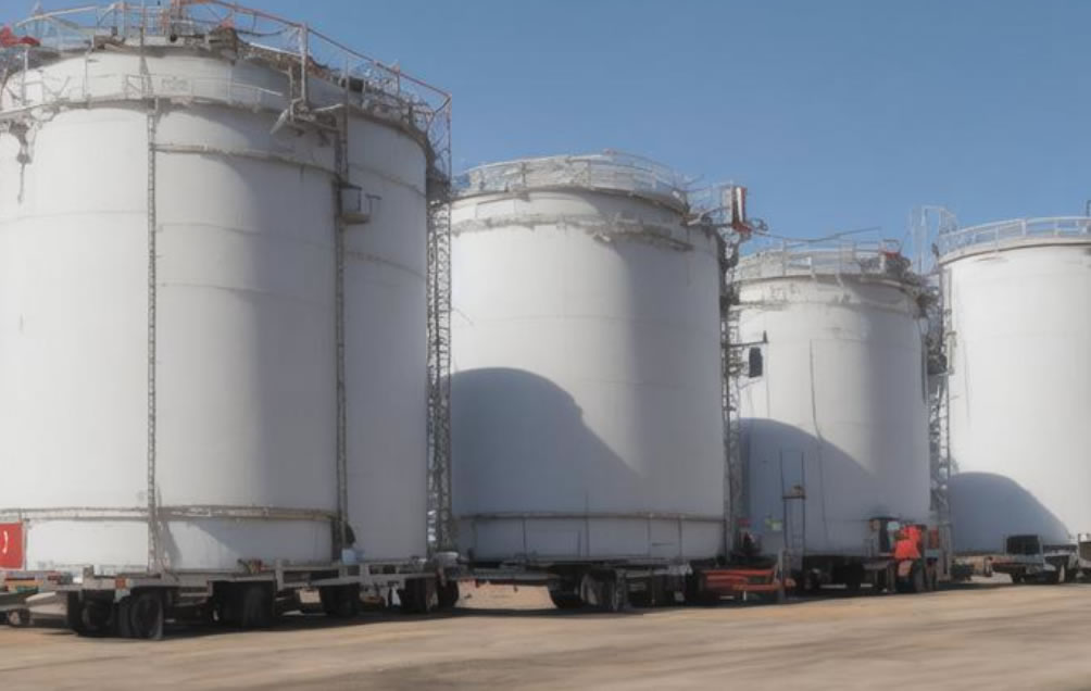
火災事故のほとんどは高温によって引き起こされます. 石油および石油化学業界では, 石油タンクエリアは重大な産業上の危険をもたらします. 大型石油貯蔵タンク内の高温は石油の揮発を引き起こす可能性があります, 火災, そして爆発さえも, 重大な死傷者や物的損害を引き起こす. 現在のところ, 一般的に使用される石油タンク火災自動警報システムの警報データは、ファイバーブラッググレーティング温度測定システムTBGから取得されます。. このタイプのセンサーは散乱測定のみが可能です. 同時に, インストール中, 液体や気体の温度を測定するには、石油タンク壁パネルに穴を開けて溶接するか、タンク内に直接入力する必要があります, これは初期の建設とその後のメンテナンスの両方に不便です. これに基づいて, の 分散型光ファイバー 温度測定システム DTS は、くすぶっている火災時の温度監視に適用できます。 (少量の煙と熱が発生します), 警告を出す, 現場のオペレーターに、事故や火災を回避するための対応措置を講じるための十分な時間を与えます。. 同時に, 企業の安全管理の自動化レベルを効果的に向上させることができます.
分散型光ファイバー温度測定システムの原理
の主な作業基盤は、 分散型光ファイバー温度測定システム 光学式時間領域反射率計の原理 (OTDR) 光ファイバーにおける後方ラマン散乱の温度効果.
The OTDR principle is mainly used for fiber optic positioning, which can achieve spatial distributed positioning of the temperature field inside the oil tank, determine the loss of various parts of the fiber optic (including damaged points), and locate temperature measurement points.
後方ラマン散乱効果とは、メイン処理ユニットのレーザー光源が波長 905nm のパルス信号をファイバーに入射したときに発生する現象を指します。, 光の伝播速度は速いのですが、, まだある程度の減衰が残っています. 一部の散乱光は入射光の反対方向に伝播します。, 散乱光に含まれるラマン信号は温度フィールド情報を伝達します. この信号はデジタル信号処理システムを通じて処理されます。 (DSP) 貯蔵タンクの温度場分布に関する情報を提供し、ファイバー全体の温度分布マップを出力します。.
分散型光ファイバー温度測定システムの設計
分散型光ファイバー温度測定システムでは、次の 3 点を確保する必要があります。: 石油タンク火災の危険性を早期に発見できます。; 火災の危険がある場所を明確に示すことができます; 火災情報を火災警報器管制システムに送信, 緊急制御システムを作動させる, 緊急遮断弁を閉じるなど, オイルパイプを切断する, およびその他の緊急作業.
機器のレイアウトは、オイルタンクの構造特性と組み合わせる必要があります。, 包括的なカバー範囲と便利な設置を考慮して. 火災警報制御システムの要件に応じて、制御システム全体が自動制御と手動制御に分かれています。, 手動制御が優先されます. 自動制御: 測定したオイルタンクの温度値が標準設定警報温度を超えた場合, 配布された 光ファイバー温度監視システム リアルタイムの火災警報データを火災警報ホストに送信します. 警報ホストはリレー動作監視信号を受信し、論理判定システムにより火災警報であることを確認します。. 手動制御: 人が火災を発見し、警報システムが作動していない場合, 彼は緊急手動警報ボタンを押すことができます. 火災警報器ホストはボタン警報信号を受信します, システムは火災であることを確認します, そして直ちに消火プログラムに入る. 警報ホストは、可聴および視覚的な火災警報を関連エリアに送信し、表示します。. 同時に, 対応する消火栓システムとリンクします, 自動泡スプレーシステム, 等, 警報信号を油槽所管理事務所にアップロードする, 人員の避難と救助活動を適時に組織するため.
監視システム全体は DTS 制御ユニットで構成されます, 温度感知光ケーブル, および光ファイバーコネクタ, 他のシステムと連携して火災警報制御システムを構築できます。,
DTSコントロールユニット
DTS コントロール ユニットは、エンジニア ステーションを介してヒューマン マシン インターフェイス環境で認定担当者によってデバッグおよびプログラミングされます。. 必要に応じてエリア長やアラームポイントを設定可能, 光ケーブルの温度軌跡をリアルタイムにPC上に表示可能. アラーム信号を強調表示することができます, 光ケーブルの損傷箇所の実際の位置の特定を含む. The area setting and alarm point position can also be changed as needed. 同時に, the entire temperature measurement system can be interconnected with other control systems through relay outputs and perform logical judgments. In fire protection applications, it can be connected to the fire alarm control host to provide signals for sound and light alarms, 正確かつ完全な信号出力; The DTS control unit can directly output signals to various digital display devices, such as central control room projectors, ディスプレイ, 等, and can set information sharing permissions based on the sharing level.
温度感知検出用光ケーブル
The temperature sensing fiber optic cable is the front-end device of the entire system, directly related to the judgment results of the DTS control unit. It can be installed on the outer wall of the oil tank. The alarm detection logic judgment for each zone can use any combination of three methods: maximum temperature in the zone (constant temperature), temperature rise rate in the zone (温度差), and the difference between the maximum temperature in the zone and the average temperature in the zone (uniformity of zone temperature) to ensure early and reliable alarm and prevent smoldering. 同時に, considering that the layout of oil tank areas is often in harsh environments, temperature sensing detection optical cables should have good characteristics such as anti biting, 耐震性, 耐食性, 等. The optical cables should have a sturdy sheath (PVC flame-retardant material), which can provide good protective characteristics. 同時に, they should also provide good temperature conductivity to ensure that fires can be detected quickly. 単一チャンネルの最長検出距離は 30KM, チャンネル数は次まで拡張できます 16. 位置決め精度は±0.5mに達します. 単一チャンネルの最速応答時間は 3.5 秒です, 起動予熱時間はすぐに使用できます.
システム全体の光ケーブルの減衰がDTSコントロールユニットの基準を超えないこと. 2kmの光ファイバー上の最大減衰率は10dBを超えてはなりません, 各接続箱は 0.4dB を超えてはなりません, 各融着ジョイントは 0.2dB を超えてはなりません.
光ファイバー接続装置
光ファイバー接続装置は、温度感知検出光ケーブルを DTS 制御ユニットに接続するためのハブとして機能します。. テールファイバーと検出用光ケーブルは光ファイバー融着点を介して接続されています, DTS コントロール ユニットの隣の光ファイバー接続ボックスにあります。.
分散型光ファイバー火災検知システム
設計要件に従って, 合計があります 4 外部浮き屋根式原油タンクと 5 内部浮き屋根 オイルタンクエリアの完成オイルタンク, 光ファイバー火災検知システムが装備されている. 浮き屋根式タンクの浮き板のシールリングに光ファイバー温度火災感知器を設置する, 垂直敷設長さの 2 倍を追加します. オイルタンク巻き取りに必要な検出用光ケーブルは約196m. 上記のデータに基づいて計算, 取る 1.15 実効冗長性の倍, 貯蔵タンクに必要な光ケーブルは2028mです.
オイルタンクの分布特性と温度監視の特定の要件に基づく, このプロジェクトでは、 “1つのタンク, 1台のマシン” デザイン用モード. 同時に, システムの安定性を高めるため, デュアルマシンホットスタンバイを採用, システム障害が発生した場合に自動的に切り替えることができます. 合計 9 光ファイバー分散型温度監視システムは、必要なオイルタンクをオンラインでリアルタイムで監視するために使用されます。.
1) 各タンクは独立したセンシング光ファイバーによって監視されます, タンクのフローティングプレートと二次シールリングの外縁に取り付けられます。.
2) が導き出した帯電防止光ファイバ 光ファイバー温度センサー タンク内のフローティングプレート上に設置されたタンクは、タンク内に直径DN25の防爆金属ホースを敷設することで保護されています。. The upper end of the explosion-proof metal hose is fixed on the flange of the manhole on the top of the tank, and the lower end of the metal hose is fixed on the floating plate inside the tank. The fixing method is non hot work, and the explosion-proof metal hose is equipotentially connected to the tank body.
3) Considering the changes in displacement at the top of the floating roof tank, in order to prevent the anti-static optical fiber passing through explosion-proof metal hoses from malfunctioning due to dragging, the reserved length should not be less than 0.5 times the height of the outer wall of the tank, and a disc optical fiber device should be used to control the anti-static optical fiber in a certain position area.
4) タンク内の浮き板に設置された光ファイバー温度センサーから導かれた帯電防止光ファイバーは、タンク外周部の直径DN25の防爆亜鉛メッキパイプを通し、エスカレーターまたはタンク壁に沿って既存の地上幹線まで導かれます。. トランキング内に敷設された通信光ケーブルと防水光ケーブル接続箱を介して接続・保護されています, エルボ部は防爆メタルホースで接続されています.
5) タンクエリア内の各石油タンクの浮き屋根に取り付けられたすべての光ファイバー温度センサーは、帯電防止光ファイバーを通じて引き出され、信号の収集と監視室への送信のために通信光ケーブルに集中します。. The communication optical cable is laid directly buried, and the elbow is connected with explosion-proof metal hose.
6) After the communication optical cable is transmitted from the tank area to the monitoring room, it is connected to the detection channel interface corresponding to the DTS host through a short distance fiber optic tail with a standard fiber optic connector, which is a fiber optic jumper.
7) Nine 2-channel DTS distributed fiber optic temperature measurement hosts were placed in the monitoring room to achieve temperature signal acquisition, temperature rise warning, over temperature alarm, 故障検出, and information management operations for the fiber optic temperature sensors installed on the oil tank site. スイッチ警報インターフェースを介して火災警報制御システムに接続し、火災警報を鳴らして消防室に表示することができます。. 現在の温度値, アラームステータス, 貯蔵タンクのすべての温度感知点の履歴温度曲線は、設定ソフトウェアの電子マップを通じて機器操作室に視覚的に表示できます。. 外部の音と光のアラームにより、機器の操作室にアラーム信号を提供することもできます。.
分散型光ファイバー温度測定システムは、光ファイバーケーブル上のあらゆる点の温度値をオンラインでリアルタイムに検出できます。, 延焼の傾向を判断できる; 温度差や温度上昇率など複数の警報方法を設定可能, 火災が発生する前に早期警告を実現するために、複数レベルの警告を設定できます。; 現場状況の変化に応じて警報ゾーンを任意に設定可能, 各ゾーンは異なるアラーム値を設定できます; 過酷な環境にも耐えられます, resist electromagnetic interference, 電磁放射を発生しません. 検出用光ケーブルの有効寿命は、 30 年, 点型光ファイバグレーティング温度測定システムの高い誤報率とメンテナンスの困難を克服. 将来の石油タンク地域の火災安全性にとって参考となる重要性があります。.

光ファイバー温度センサー, インテリジェント監視システム, 中国の分散型光ファイバーメーカー
 |
 |
 |