 INNO 光ファイバー温度センサー ,温度監視システム.
- ケーブル接続温度監視 過剰を防ぐ 85% 過熱故障の原因, ケーブルの接合部が占める割合が大きいため、 40% 接触抵抗によって引き起こされる配電システムの障害の発生
- 光ファイバー温度センサー 100kVの電気絶縁を提供, 高電圧環境における温度測定の根本的な課題を解決
- 単一監視システムのサポート 4-16 バスバーを包括的にカバーする測定ポイント, 受信および送信ケーブル接続, および動的接触点
- ±0.5℃の精度と0.5秒の応答時間により、ケーブル接合部の異常な温度上昇の早期警告兆候を捕捉します
- IP67 保護等級により、次のような過酷な環境でも信頼性の高い動作が保証されます。 開閉装置キャビネット, ケーブル保管庫, そして地下トンネル
- 20-年間メンテナンスフリーの設計により、定期的な校正の必要性がなくなり、長期的な運用コストが削減されます。
目次
1. ケーブル接続が配電システムの過熱に対して最も脆弱な箇所であるのはなぜですか?

Cable connections represent the weakest thermal links in electrical distribution networks, 以上を説明する 40% of system failures attributed to excessive heating. Unlike continuous conductors with uniform cross-sections, connection points introduce contact resistance that generates localized heat under load current.
1.1 Physical Causes of Increased Contact Resistance
Three primary mechanisms drive contact resistance degradation in ケーブル接続: surface oxidation creates insulating layers on conductor interfaces, mechanical loosening from thermal cycling reduces contact pressure, and contamination from dust or moisture forms resistive films. Each mechanism incrementally increases resistance, compounding heat generation through I²R losses.
1.2 ケーブル接続の障害と経済的損失の統計的分析
業界データは次のことを明らかにしています ケーブル接続温度監視 防ぐことができる 85% 過熱関連の故障の発生. ケーブル接続部の故障による計画外の停止により、産業施設に平均で次のようなコストがかかります。 $50,000-$500,000 生産損失を考慮した場合のインシデントごと, 機器の損傷, および緊急修理費用. プロアクティブな温度監視により、障害の防止を通じて即座に投資収益率を実現します.
2. 基本的な制限によって何が起こるか 従来のケーブル接続温度監視 テクノロジーが持つ?

従来の温度測定アプローチを適用すると、乗り越えられない障害に直面します。 高電圧ケーブルの接続 密閉された開閉装置環境で.
2.1 赤外線サーモグラフィーの視覚障害と精度の問題
赤外線カメラは測定対象物への直接の見通し線を必要とします, making them ineffective for enclosed switchgear where cable connections are surrounded by grounded metal compartments. Viewing windows introduce measurement errors from glass transmission characteristics, while periodic manual inspections miss transient overheating events between inspection intervals. Environmental factors including ambient temperature, 湿度, and surface emissivity variations further compromise infrared measurement accuracy.
2.2 Thermocouple Insulation Risks in High Voltage Cabinets
Metal thermocouple wires create conductive paths between high voltage conductors and grounded monitoring equipment, requiring extensive insulation that increases installation complexity and introduces failure points. Electromagnetic interference from switching transients and load currents induces noise in thermocouple signals, corrupting measurements. The fundamental incompatibility between metallic sensors and high voltage environments limits thermocouple applications to low voltage installations.
3. どうやって Fiber Optic Temperature Sensors Achieve Safe Isolation Measurement for Cable Connections?
光ファイバー温度センサー solve the electrical isolation challenge through all-dielectric construction containing zero conductive materials.
3.1 All-Dielectric Structure Insulation Principle
The complete signal path from sensing point to monitoring equipment consists of pure glass optical fiber, ceramic or polymer probe housing, and rare-earth fluorescent sensing elements. This entirely non-conductive design provides inherent electrical isolation without requiring additional insulating barriers. センサーは、完全な温度測定機能を維持しながら、電流に対する無限のインピーダンスとして機能します。.
3.2 100kV 耐電圧定格 技術保証
標準 光ファイバー温度センサー のために 開閉装置の温度監視 アプリケーションは高電圧試験を受けて、100kVを超える耐性を検証します. この電圧定格により、安全上の問題や測定の干渉を引き起こすことなく、あらゆる配電電圧レベルで通電された導体に直接取り付けることができます。. 電気的絶縁によりグランドループが排除されます, コモンモード電圧の影響, 従来のセンサー技術を悩ませる電磁干渉.
4. 入力ケーブル接続と出力ケーブル接続の温度測定要件の違いは何ですか?
4.1 受電側大電流接続ホットスポット分散
入力ケーブル接続 通常、下流の配電機器の全負荷電流を処理します, 公共サービスの入口ポイントで集中的な熱負荷が発生する. これらの接続では、最小限の変動で継続的に大電流が流れます。, 定常状態の熱解析が可能. 主な監視目的は、温度が有害なレベルに達する前に、酸化や機械的緩みによる徐々に増加する抵抗を検出することに重点を置いています。.
4.2 2次側負荷変動温度特性
発信ケーブル接続 個々の負荷に対応する場合、負荷サイクルと相関する動的な熱挙動を示します。. 温度測定では、負荷変化時の通常の変動と、接続の劣化を示す異常な温度上昇を考慮する必要があります。. マルチポイント監視により、負荷電流に対する予想される熱応答と、メンテナンス介入が必要な接続問題の発生とを区別します。.
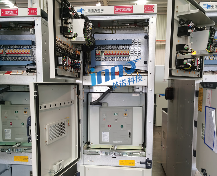
5. を構成するコアコンポーネントは何ですか 完全な開閉装置温度監視システム 建築?

5.1 System Integration of Fiber Probes, 送信機, and Display Instruments
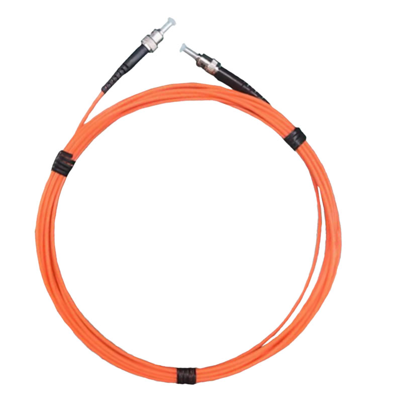
包括的な cable connection online monitoring system integrates multiple functional elements: 光ファイバー温度プローブ installed at measurement points, optical fiber transmission cables routing signals to monitoring equipment, fluorescent fiber temperature transmitters providing optical excitation and signal processing, and LCD display instruments presenting real-time data with alarm management.
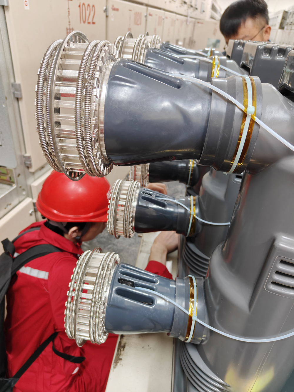
5.2 Typical Switchgear Temperature Measurement System Configuration Diagram Analysis
The installation schematic reveals strategic sensor placement throughout switchgear compartments. Yellow-marked positions ① indicate busbar monitoring points at main copper bar connections. Orange positions ⑥ show incoming and outgoing cable temperature measurement locations where power cables connect to switchgear terminals. Red position ⑤ identifies dynamic contact point monitoring on circuit breaker switching mechanisms. Green position ③ locates the fiber optic temperature transmitter housing multi-channel measurement electronics. Blue position ② displays the LCD monitoring instrument providing operator interface. Purple position ④ shows the fiber optic adapter flange managing multiple probe connections to the transmitter unit.
6. 高電圧ケーブル接続に光ファイバー温度測定ソリューションを使用する必要がある理由?
6.1 Insulation Distance Requirements for 10kV/35kV Cable Connections
High voltage cable connections in 10kV and 35kV switchgear require minimum air insulation clearances of 160mm and 310mm respectively according to IEC 62271-200 標準. Conventional sensors with conductive wiring violate these clearances or require bulky insulating standoffs that complicate installation. The all-dielectric nature of 光ファイバーセンサー eliminates insulation distance concerns, allowing direct mounting on energized conductors.
6.2 Safety Hazards of Traditional Metallic Sensors
Metal sensor components introduced into high voltage environments create multiple hazards including partial discharge inception points, fault current paths during equipment failures, and electromagnetic coupling that induces dangerous voltages on grounded monitoring equipment. These safety concerns prohibit use of conventional sensors in high voltage applications where 光ファイバー温度測定 provides the only viable solution.
7. 配電盤温度センサーはどのようにして多点同時監視を実現するのか?
7.1 4-16 Channel Fluorescent Fiber Optic Temperature Measurement System Configuration
Multi-point temperature monitoring systems connect 4, 8, 12, または 16 independent 光ファイバー温度プローブ マルチチャネル光スイッチングまたは並列測定チャネルを介して単一の送信ユニットに接続. 各プローブは専用の光路上で動作します, チャンネル間の信号干渉がなく、すべての測定ポイントから同時に温度を取得できます。. 集中型アーキテクチャにより、測定場所ごとに個別の単一チャネル システムを導入する場合と比較して、機器コストが削減されます。.
7.2 多点温度データの一元取得
の 蛍光光ファイバー温度計 送信機は接続されているすべてのプローブを順番にまたは同時に励起します。, 蛍光減衰特性を測定する, 光信号を温度値に変換します. デジタル信号処理アルゴリズムは、工場出荷時の校正データと環境補償を適用して、各チャネルの正確な温度測定値を提供します。. The system presents all measurement points through unified display interfaces and communication protocols.
8. バスバー接続温度の監視が配電キャビネットの保護の重要な焦点である理由?
8.1 Stress Concentration Phenomena at Copper Bar Connection Points
Busbar systems use bolted mechanical connections to join copper bar sections and create branch connections. These joints concentrate mechanical stress at contact interfaces, making them susceptible to loosening from thermal expansion cycling and mechanical vibration. Even minor reductions in bolt torque significantly increase contact resistance and heat generation.
8.2 Oxidation and Corrosion Mechanisms at Busbar Overlap Surfaces
Copper busbar surfaces oxidize when exposed to air, forming copper oxide layers that exhibit higher electrical resistance than pure copper. Bolted connections trap oxygen and moisture at interfaces, accelerating oxidation and creating progressive resistance increase. 温度監視 detects the thermal signature of this electrochemical degradation before it causes failures, enabling preventive maintenance to restore connection quality.
9. How to Implement Online Temperature Monitoring for Breaker Dynamic and Static Contact Points?
9.1 Vacuum Circuit Breaker Contact Wear Characteristics
Vacuum circuit breakers experience contact erosion from each switching operation, gradually reducing contact surface area and increasing contact resistance. The enclosed vacuum bottle prevents visual inspection of contact condition, making temperature monitoring the primary method for detecting excessive wear requiring maintenance. 光ファイバーセンサー mounted on breaker terminals track contact temperature rise as wear progresses.
9.2 SF6 Circuit Breaker Contact Resistance Monitoring
SF6 circuit breakers use high-pressure gas to extinguish arcs during interruption. 接触面では、アーク放電により炭素堆積物が発生したり、抵抗を増加させる機械的な位置合わせの問題が発生したりする可能性があります。. ブレーカー端子の温度測定により、負荷電流下での異常加熱による接点の劣化が明らかになります, コンタクトの保守間隔を最適化する、状態ベースのメンテナンス プログラムのサポート.
10. What Are the Measurement Point Layout Principles for Cable Terminal Temperature Monitoring Systems?
10.1 ストレス コーン領域の温度感受性
ケーブル端末温度 モニタリングは、高電圧ケーブルの絶縁が空気絶縁に移行するストレスリリーフコーンに焦点を当てています。. これらの領域は集中した電気的ストレスを受け、不適切に取り付けられた場合、部分放電や発熱を引き起こす可能性があります。. 温度センサーは、完全な故障に至る前に絶縁問題を示す熱異常を検出します。.
10.2 アース線接続点の優先監視
Cable terminal ground connections carry fault currents during short circuit events and must maintain low resistance for effective protection system operation. 腐食したり緩んだアース接続により高い抵抗が発生し、障害時にケーブルの被覆に危険な電圧上昇が生じます。. 定期的な温度監視により、総合的な管理の一環として接地接続の完全性が検証されます。 ケーブル接続温度監視 プログラム.
11. How to Scientifically Position Sensors in Incoming and Outgoing Cable Temperature Measurement Systems?
11.1 三相ケーブル接続のバランス監視
入出力ケーブルの温度測定 システムは、非対称の加熱パターンを検出するために、三相導体すべてにセンサーを取り付けます。. 適切にバランスの取れた三相負荷では、すべての相で同様の温度が生成されます。, 一方、単相の過負荷または相固有の接続の問題により、相間に温度差が生じます。. 三相温度の比較分析により、迅速な故障の特定と分類が可能になります.
11.2 単相地絡の温度識別
High resistance ground faults may not trip overcurrent protection but cause localized heating at fault points. Multi-point temperature monitoring detects abnormal temperature rise on affected phases, providing early warning of developing insulation failures. The measurement data supports predictive maintenance by identifying cables requiring detailed inspection before catastrophic failures occur.
12. What Functions Does the LCD Display Instrument Provide in Cable Connection Online Monitoring Systems?
12.1 Multi-Channel Real-Time Temperature Curve Display
の LCD display instrument simultaneously presents current temperature readings for all monitored points with graphical trend displays showing temperature evolution over time. Color-coded indicators highlight normal, 警告, and alarm conditions for each measurement channel. Operators monitor the complete thermal profile of switchgear from a single interface, quickly identifying developing problems requiring attention.
12.2 Historical Data Query and Trend Analysis
Integrated data logging captures temperature measurements at configurable intervals, creating permanent records for analysis and documentation. Historical data review reveals gradual temperature trends indicating progressive connection degradation, supports troubleshooting of intermittent problems, and provides evidence for regulatory compliance and quality management systems.
13. What Is the Working Principle of 蛍光ファイバーによる温度測定 テクノロジー?

13.1 Temperature Response Characteristics of Rare-Earth Fluorescent Materials
蛍光光ファイバー温度計 employs rare-earth phosphor compounds exhibiting temperature-dependent fluorescence decay. The transmitter sends light pulses through optical fiber to excite fluorescent material at the probe tip. Excited electrons in the phosphor material absorb energy and subsequently emit fluorescence at a different wavelength, with decay time that varies predictably and repeatably with temperature.
13.2 Accuracy Advantages of Fluorescence Lifetime Measurement
Precision timing electronics measure fluorescence decay duration with nanosecond resolution, converting this optical time constant into accurate temperature readings. The measurement principle depends solely on fluorescence kinetics, providing immunity to optical power variations, ファイバーの曲げ損失, and connector condition that affect intensity-based measurement techniques. This approach delivers ±0.5℃の精度 with exceptional long-term stability.
14. What Practical Value Does ±0.5°C Measurement Accuracy Offer for Cable Connection Fault Prevention?

14.1 Early Detection Capability for Minor Temperature Rise
の ±0.5℃の精度 specification enables detection of temperature increases as small as 2-3°C above normal operating levels, providing early warning before connections reach dangerous temperatures. Cable joints typically exhibit gradual temperature rise over weeks or months as contact resistance increases. High accuracy measurement captures this progression in initial stages when simple maintenance can restore normal conditions.
14.2 Comparative Analysis with Environmental Temperature Compensation
Cable connection temperature monitoring systems measure both connection temperatures and ambient temperature within switchgear enclosures. Subtracting ambient temperature from connection readings yields temperature rise values that directly indicate connection condition independent of environmental variations. Accurate ambient measurement allows precise calculation of these temperature differentials for reliable fault detection.
15. How Do Temperature Measurement Solutions Differ Between Cable Intermediate Joints and Terminal Joints?
15.1 Temperature Characteristics of Intermediate Joint Shielding Layer Connections
Cable intermediate joints in underground distribution systems join cable sections in manholes or vaults. These joints must maintain electrical continuity of metallic shielding layers while providing high voltage insulation. Shield connection points can develop high resistance from corrosion in damp environments, creating localized heating. 光ファイバー温度センサー with IP68 waterproof rating monitor these submerged connections reliably for years without degradation.
15.2 Hot Spot Distribution in Terminal Stress Cone Areas
ケーブル端末温度 measurement focuses on the stress cone region where cable insulation terminates. Improper installation techniques or insulation defects concentrate electrical stress, causing partial discharge and heating. Temperature monitoring detects these thermal anomalies, supporting quality verification of terminal installations and ongoing condition assessment during service.
16. What Are Typical Application Cases of Cable Connection Temperature Monitoring in 10kV Switchgear?
16.1 Ring Main Unit Incoming and Outgoing Line Temperature Measurement Configuration
10kV ring main units serving urban distribution networks use compact switchgear with limited space for temperature monitoring equipment. 光ファイバー温度センサー with 600μm diameter probes fit within confined compartments, monitoring cable connections at loop-in, loop-out, and transformer feeder positions. The small sensor size and flexible optical fiber enable installation without switchgear modifications.
16.2 Comprehensive Monitoring for Fixed Switchgear
Industrial facility 10kV switchgear installations benefit from complete 多点温度監視 covering busbar connections, サーキットブレーカーの端子, ケーブル接続, and transformer terminations. を備えたシステム 12-16 measurement channels provide comprehensive thermal surveillance, detecting problems anywhere in the electrical distribution path from utility service entrance through load feeders.
17. How to Implement Cable Connection Temperature Online Monitoring in 35kV High Voltage Switchgear?
17.1 Insulation Distance Limitations in High Voltage Cabinets
35kV 開閉装置の温度監視 must maintain 310mm minimum phase-to-ground clearances and 370mm phase-to-phase spacings. 全誘電体構造 光ファイバーセンサー allows installation directly on energized conductors without compromising these safety distances. Flexible optical fiber routes through existing cable glands and bushing penetrations without requiring additional insulated feedthroughs.
17.2 Secure Pathway Design for Fiber Optic Routing
Optical fiber routing within high voltage switchgear follows established cable pathways, maintaining separation from live parts and avoiding sharp bends that could damage fiber. Protective conduit shields fiber from mechanical damage during maintenance activities. 適切なファイバー管理により、開閉装置の安全性評価を維持し、将来のメンテナンスアクセスを簡素化しながら、信頼性の高い信号伝送が保証されます。.
18. How to Achieve Remote Temperature Monitoring in Underground Cable Vaults and Tunnels?
18.1 IP68防水プローブのカプセル化により湿気から保護
地下ケーブル敷設では高湿度と定期的な浸水が発生し、従来のセンサーが破壊されます。. 光ファイバー温度プローブ IP68防水等級により、測定精度を維持しながら連続水没に耐えます. 密閉されたプローブ構造により、光学部品に損傷を与える湿気の侵入を防ぎます。, 過酷な地下環境でも数十年にわたる信頼性の高い動作を保証.
18.2 長距離光ファイバー伝送の信号保証
蛍光ファイバーシステムは、超過の光ファイバーの配線をサポートします。 500 信号の劣化やリピータを発生させることなく、測定ポイントから監視装置まで数メートルの距離を維持できます。. This capability enables centralized monitoring of multiple cable vaults from a single control room location. The low optical loss of standard communication-grade fiber ensures reliable transmission over extended distances encountered in utility cable networks.
19. How to Set Scientific Alarm Thresholds for Cable Connection Temperature Monitoring Systems?
19.1 IEC 60439 Standard Temperature Rise Limits
International standards specify maximum allowable temperature rise for electrical connections based on conductor material and insulation class. Bare copper connections typically limit temperature rise to 65°C above ambient, while insulated connections allow 70-80°C rise depending on insulation rating. ケーブル接続温度監視 alarm thresholds align with these standards, providing warning before temperatures exceed equipment ratings.
19.2 Three-Level Alarm Strategy: 事前警告, アラーム, and Trip
Sophisticated monitoring systems implement multiple alarm levels supporting progressive response to developing problems. Pre-warning alarms at 80% of maximum allowable temperature alert operators to schedule maintenance during planned outages. High-level alarms at 90% threshold trigger immediate investigation and load reduction. Critical alarms at 100% rating can initiate automatic circuit breaker tripping to prevent equipment damage from extreme overheating.
20. How Do Multi-Point Temperature Monitoring Systems Interface with Distribution Automation SCADA?
20.1 Modbus RTU/TCP Communication Protocol Configuration
Fiber optic temperature transmitters 監視制御およびデータ収集システムとの統合のために、Modbus RTU シリアル通信および Modbus TCP イーサネット ネットワーキングを提供します. 標準プロトコルの実装により、SCADA システムが温度データをポーリングできるようになります, アラームステータス, 監視装置からのシステム診断. 構成ツールは、システム アーキテクチャ要件に一致する SCADA ポイント アドレスに測定チャネルをマッピングします。.
20.2 IEC 61850 インテリジェント変電所通信規格
最新のデジタル変電所は IEC を使用しています 61850 デバイスの通信と統合のためのプロトコル. 高度な 温度監視システム IECをサポート 61850 汎用オブジェクト指向変電所イベントを備えたクライアント/サーバー モデル (ガチョウ) 高速アラーム伝播のためのメッセージング. この標準ベースのアプローチにより、デジタル変電所自動化システムとのシームレスな統合が可能になります。.
21. How to Implement Protection-Grade Temperature Measurement for Outdoor Cable Junction Box Connections?
21.1 IP67 屋外保護要件
屋外のケーブル接続箱が雨に見舞われる, 雪, 氷, and direct sunlight requiring 光ファイバー温度センサー with IP67 minimum protection rating. Sealed probe housings prevent water and dust ingress while maintaining thermal contact with monitored conductors. UV-resistant materials prevent degradation from sunlight exposure during decades of outdoor service.
21.2 Wide Temperature Range -40°C to +125°C Adaptability
Outdoor installations encounter extreme ambient temperatures from arctic winters to desert summers. Fiber temperature sensors specified for -40°C to +125°C operation maintain accuracy and reliability across this range without recalibration. The wide operating window ensures measurement capability in all climates and seasons without seasonal adjustments.
22. Why Are Copper-Aluminum Transition Cable Connections Priority Objects for Temperature Monitoring?
22.1 Electrochemical Corrosion Causing Increased Contact Resistance
Copper-aluminum transition connections join dissimilar metals with different electrochemical potentials. Moisture exposure creates galvanic corrosion at the interface, progressively increasing contact resistance and heat generation. This electrochemical mechanism accelerates degradation compared to copper-to-copper or aluminum-to-aluminum connections, making temperature monitoring especially valuable for bimetallic joints.
22.2 Temperature Rise Rate Characteristics of Copper-Aluminum Connections
Bimetallic connections exhibit faster temperature rise rates when experiencing degradation due to oxide formation and corrosion product buildup. ケーブル接続温度監視 detects these accelerated thermal changes, providing shorter warning times before failure compared to homogeneous metal connections. Frequent measurement updates and sensitive alarm thresholds optimize early detection for these high-risk connection types.
23. How to Distinguish Between Connection Problems and Overload When Cable Connection Temperature Abnormalities Occur?
23.1 Three-Phase Temperature Comparison Analysis Methods
Overload conditions affect all three phases equally, producing similar temperature rises on all conductors. Connection problems typically affect single phases, creating asymmetric heating patterns. Comparing temperatures between phases identifies whether heating stems from excessive load current or localized connection resistance. Temperature differences exceeding 10°C between phases indicate connection problems requiring maintenance regardless of load levels.
23.2 Correlation Between Load Current and Temperature Rise
Integrating temperature monitoring with current measurement establishes the relationship between load and temperature for each connection. Properly functioning connections exhibit predictable temperature rise proportional to current squared (I²R加熱). Connections developing problems show temperature rise exceeding expected values for measured current levels. This correlation analysis separates normal thermal response from abnormal resistance-driven heating.
24. How to Verify Long-Term Reliability of Cable Connection Temperature Measurement Systems?
24.1 Standard Procedures for System Commissioning Testing
専門的な設置には、すべての測定チャンネルを検証する包括的な試運転テストが含まれます, 通信インターフェース, およびアラーム機能. テストによりセンサーの熱接触が適切であることを確認, 光信号の品質, 測定精度, 制御機器とのシステム統合. コミッショニング結果を文書化することで、将来の比較のためのベースラインパフォーマンスを確立します.
24.2 20年間メンテナンスフリー設計の検証データ
蛍光光ファイバー温度センサー 加速老化試験と現場での経験により、優れた長期安定性を実証. 希土類蛍光物質の安定した光学特性により、ドリフトなく数十年間校正精度が維持されます。. 工場出荷時の校正はセンサーの動作寿命全体にわたって継続されます, 再校正の必要性と関連コストの排除. 以上のフィールド設置 15 年間の連続稼働により、メンテナンスフリー設計の主張が裏付けられます.
25. Can Existing Operational Switchgear Be Retrofitted with Temperature Monitoring Systems?
通電中の開閉装置は受信可能 温度監視 計画的なメンテナンス停止中に大規模な変更を加えることなくアップグレード可能. コンパクト 光ファイバーセンサー 穴あけや溶接を必要としない接着剤取り付けまたは機械式クランプを使用してケーブル接続に取り付けます. 既存のケーブル エントリ ポイントまたは小径貫通部を通る光ファイバの配線により、開閉装置の定格が維持されます。. 非侵襲的な設置アプローチにより、機器を完全に交換することなく、監視の強化が必要な老朽化したインフラストラクチャの改修をコスト効率よく行うことができます。.
レトロフィットプロジェクトは通常、次の期間内に設置を完了します。 4-8 定期メンテナンス期間中の開閉装置セクションあたりの時間. システムのコミッショニングとオペレーターのトレーニングを追加 2-4 時間, 停止開始からサービス復帰まで同日完了可能. This rapid deployment minimizes downtime costs while delivering immediate monitoring capability for critical assets.
よくある質問
What is the normal operating temperature range for cable connections?
Cable connections typically operate 30-50°C above ambient temperature under rated load conditions. Temperatures exceeding 80-90°C total temperature or 65°C temperature rise above ambient indicate developing problems requiring investigation. 温度監視システム track both absolute temperature and temperature rise to detect abnormal conditions.
How many temperature measurement points can a single monitoring host connect?
標準 multi-point temperature monitoring systems サポート 4, 8, 12, または 16 independent measurement channels per transmitter unit. Larger installations use multiple transmitters networked through communication systems to monitor hundreds of points from centralized control interfaces.
What is the service life of fiber optic probes?
光ファイバー温度センサー feature 20-year design life with maintenance-free operation. The all-glass optical components and stable fluorescent materials resist degradation from temperature cycling, environmental exposure, and time. Field installations demonstrate reliable operation exceeding 15 years without performance degradation.
Do systems require periodic calibration?
定期的な校正は必要ありません. 蛍光寿命に基づく基本的な測定原理はいつまでも安定しています. 工場出荷時の校正はセンサーの動作寿命全体にわたって継続されます, 時間の経過とともにドリフトする従来のセンサーに関連する継続的な再校正コストとダウンタイムを排除します。.
どのケーブル接続材質を監視できるか?
Fiber temperature sensors 銅を含むあらゆる導体材料の接続を監視, アルミニウム, 銅とアルミニウムの転移, および錫メッキの表面. 測定技術は表面組成に関係なく温度に反応します, 放射率, または他の技術に影響を与える酸化状態.
システムは屋外環境に適していますか?
はい. 光ファイバー温度プローブ IP67屋外定格で雨に耐えます, 雪, 氷, そして直射日光. -40°C ~ +125°C の動作温度範囲により、あらゆる気候において信頼性の高い測定が保証されます. 耐紫外線性素材により、数十年にわたる屋外暴露による劣化を防止.
How to distinguish between connection overheating and elevated ambient temperature?
Systems measure both connection temperature and switchgear ambient temperature. Subtracting ambient from connection readings yields temperature rise values indicating connection condition independent of environmental variations. Alarms trigger on excessive temperature rise rather than absolute temperature to avoid false alarms during hot weather.
Can temperature monitoring be added to existing operational switchgear?
はい. Retrofit installations complete during planned maintenance outages using non-invasive mounting methods. The compact sensors and flexible optical fiber install without extensive switchgear modifications, preserving equipment ratings while adding monitoring capability to aging infrastructure.
Professional Cable Connection Temperature Monitoring Solutions
福州イノベーション電子科学&テック株式会社, 株式会社. を専門とする 光ファイバー温度監視システム for electrical distribution equipment. 以来 2011, we have delivered reliable temperature measurement solutions for 開閉装置, 変圧器, and power cable systems serving utility, 工業用, and commercial applications worldwide.
Technical Support for Your Application
Our engineering team provides expert guidance for:
- 多点監視システムの設計とセンサー配置の最適化
- 特定の設置要件に合わせたカスタム プローブ構成
- SCADA システムと Modbus および IEC の統合 61850 プロトコル
- 既存の開閉装置の改修設置計画
- 包括的な試運転サポートとオペレータートレーニング
メーカー: 福州イノベーション電子科学&テック株式会社, 株式会社.
設立: 2011
電子メール: web@fjinno.net
WhatsApp/WeChat/電話: +86 13599070393
QQ: 3408968340
住所: 連東U穀物ネットワーキング工業団地, 興業西路12号, 福州, 福建省, 中国
Webサイト: www.fjinno.net
免責事項
このテクニカル ガイドでは、ケーブル接続温度監視システムと光ファイバー センサー テクノロジーに関する一般的な情報を提供します。. 提示された情報は、12 月現在の業界の慣行と基準を反映しています。 2025. 具体的な製品仕様, 性能特性, 認定はモデルによって異なる場合があります, 構成, そしてアプリケーション.
温度監視システムの選択と設置は、適用される電気規定に準拠する必要があります, 安全規格, および機器メーカーの仕様. ユーザーは、提案された監視ソリューションがすべての規制要件を満たしていることを確認する責任があります。, safety ratings, and performance needs for their specific applications. This document does not constitute engineering specifications, installation instructions, or regulatory guidance.
Proper system design requires detailed analysis of electrical equipment characteristics, 環境条件, および運用要件. Contact our technical team for application-specific recommendations, detailed specifications, certification documentation, and installation support. Performance specifications represent typical values under standard conditions and may vary based on operating environment and system configuration. Installation should be performed by qualified electrical personnel following established safety procedures and equipment manufacturer guidelines.

光ファイバー温度センサー, インテリジェント監視システム, 中国の分散型光ファイバーメーカー
 |
 |
 |