 Sensori di temperatura a fibra ottica INNO ,sistemi di monitoraggio della temperatura.
- Transformer winding temperature is the most critical parameter affecting insulation life and operational safety.
- Traditional methods such as oil temperature indicators (FATTO), indicatori della temperatura dell'avvolgimento (WTI), E RTD/thermocouple sensors each have inherent limitations in accuracy and direct measurement capability.
- Sistemi di monitoraggio della temperatura a fibra ottica fluorescente based on GaAs sensing technology offer direct, in tempo reale, and high-voltage-immune winding temperature measurement.
- Un singolo demodulatore di temperatura in fibra ottica supports 1–64 channels, RS485 communication, e oltre 25 years of service life.
- This article provides a full comparison table, global application cases, and expert guidance for selecting the right monitoring solution.
Sommario
- What Is Transformer Winding Temperature?
- Causes and Hazards of Winding Temperature Rise
- International Standards and Temperature Limits
- Traditional Method: Indicatore della temperatura dell'olio (FATTO)
- Traditional Method: Indicatore della temperatura dell'avvolgimento (WTI)
- Traditional Method: Thermocouple and RTD Sensors
- Raccomandato: Sistema di monitoraggio della temperatura in fibra ottica fluorescente
- Technical Comparison of All Four Methods
- Casi applicativi globali
- Winding Temperature Protection and Control Logic
- Ottieni una soluzione personalizzata
- Domande frequenti (Domande frequenti)
- Disclaimer
1. What Is Transformer Winding Temperature?

Transformer winding temperature refers to the actual thermal condition of the copper or aluminum conductors inside a power transformer. Among all measurable parameters — including temperatura dell'olio, livelli di gas disciolto, and load current — the winding hot-spot temperature is universally recognized as the single most important factor determining transformer health and remaining insulation life.
When a transformer carries load, current flowing through the windings produces resistive losses (I²R losses) e perdite per correnti parassite, both generating heat. This heat accumulates in the winding conductors and must be dissipated through the insulating oil and cooling system. The point within the winding structure that reaches the highest temperature is known as the punto caldo tortuoso. Accurately monitoring this hot-spot temperature is essential for safe loading decisions, protezione termica, and long-term asset management.
2. Causes and Hazards of Winding Temperature Rise
2.1 Primary Causes
Winding temperature rise is driven by several factors. Load current is the dominant contributor — as current increases, I²R losses increase proportionally with the square of the current. Eddy current and stray losses in the conductors and structural components generate additional heat. Ambient temperature and solar radiation directly affect the transformer’s ability to reject heat. Inoltre, degraded cooling systems — such as blocked radiators, failed fans, or deteriorated oil — reduce heat dissipation capacity and cause elevated winding temperatures.
2.2 Hazards of Excessive Winding Temperature
Excessive winding temperature accelerates the thermal degradation of cellulose insulation. According to the well-established Arrhenius aging model referenced in IEEE Std C57.91, the rate of insulation aging approximately doubles for every 6–7°C increase above the rated hot-spot temperature. Sustained overheating leads to reduced dielectric strength, formation of combustible gases, eventual insulation failure, and potentially catastrophic transformer damage. Reliable winding temperature monitoring is therefore not optional — it is a fundamental requirement for transformer protection.
3. International Standards and Temperature Limits
Several international standards govern transformer winding temperature limits and monitoring requirements. CEI 60076-2 specifies that the average winding temperature rise shall not exceed 65K above ambient for oil-immersed transformers, with a hot-spot temperature rise limit of 78K. IEEE Std C57.12.00 similarly defines a 65°C average winding rise for most classes. IEEE Std C57.91 provides detailed thermal loading guidelines, metodi di calcolo degli hot-spot, and insulation aging equations. CEI 60354 (now absorbed into IEC 60076-7) offers loading guidance based on thermal modeling. These standards collectively establish that continuous winding hot-spot temperatures should generally remain below 110–120°C for normal life expectancy, with the maximum permissible value depending on the insulation class and loading duration.
4. Traditional Method: Indicatore della temperatura dell'olio (FATTO)
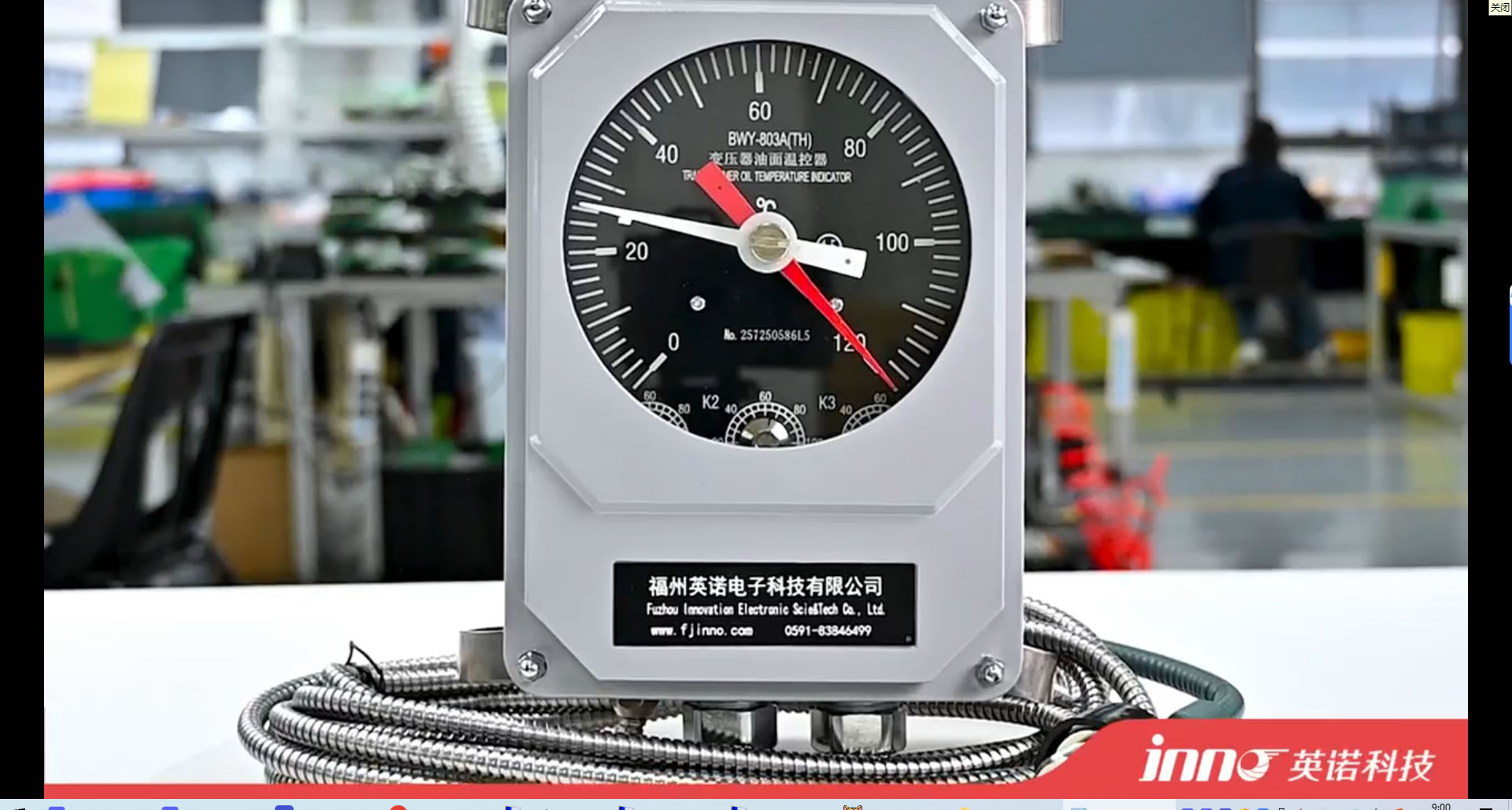
4.1 Principio di funzionamento
UN indicatore della temperatura dell'olio (FATTO), also commonly referred to as an termometro dell'olio O oil temperature gauge, measures the temperature of the insulating oil at or near the top of the transformer tank. The most common type uses a liquid-expansion (mercury or organic-filled) capillary system. A sensing bulb is inserted into a thermometer pocket welded on the transformer tank. As the oil temperature changes, the liquid in the bulb expands or contracts, driving a pointer on the dial gauge via the capillary tube.
4.2 Typical Parameters
Standard FATTO devices offer a measurement range of 0–150°C, with an accuracy of approximately ±3–5°C. They typically include adjustable alarm and trip contacts (commonly set at 85°C and 95°C for top-oil temperature). The capillary length is usually available from 1 m to 20 M. Response time is relatively slow, typically in the range of several minutes.
4.3 Limitazioni
IL indicatore della temperatura dell'olio measures only the top-oil temperature, which does not directly represent the winding hot-spot temperature. The actual winding hot spot can be 20–40°C higher than the measured oil temperature. Mechanical components are subject to drift and aging over time, and the device cannot be easily integrated into modern digital monitoring systems without additional signal converters.
5. Traditional Method: Indicatore della temperatura dell'avvolgimento (WTI)
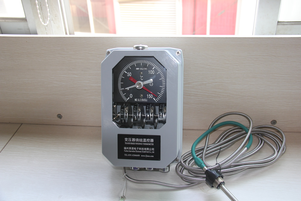
5.1 Principio di funzionamento
UN indicatore della temperatura dell'avvolgimento (WTI) uses a thermal imaging (simulation) method to estimate the winding hot-spot temperature without directly measuring the winding conductor. A current transformer (CT) on the bushing provides a signal proportional to the load current. This signal feeds a small heating element coiled around the sensing bulb of a thermometer pocket. The combination of the ambient oil temperature and the thermal contribution from the heating resistor simulates the thermal gradient between the oil and the winding, producing an indirect estimate of the winding hot-spot temperature.
5.2 Calibration and Setup
During factory heat-run testing, IL WTI is calibrated by adjusting the heating resistor current to match the measured winding-to-oil gradient at rated load. This calibration is specific to one loading condition. In the field, the relationship between load current and actual temperature gradient may deviate from the factory setting due to varying cooling conditions, oil aging, and non-linear thermal dynamics.
5.3 Typical Parameters
A standard indicatore della temperatura dell'avvolgimento provides a display range of 0–200°C with an accuracy of approximately ±3–5°C for the simulated value. It includes two to four adjustable contacts for fan start, pump start, allarme, and trip functions. Response time is moderate, typically 5–15 minutes due to the thermal inertia of the simulation element.
5.4 Limitazioni
Perché il WTI relies on an indirect thermal model rather than a direct measurement, its reading is an approximation. Under transient loading conditions, overload events, or when cooling system performance changes, the WTI may significantly deviate from the actual winding temperature. It is also vulnerable to calibration drift over the transformer’s service life.
6. Traditional Method: Thermocouple and RTD Sensors
6.1 Principio di funzionamento
Sensori termocoppia (typically Type T or Type K) generate a voltage proportional to the temperature difference between the sensing junction and a reference junction. Platinum resistance temperature detectors (Termoresistenza Pt100) measure temperature by detecting the change in electrical resistance of a platinum element. Both types can be embedded within the transformer winding during manufacturing to provide direct temperature readings of the conductor.
6.2 Typical Parameters
UN Termoresistenza Pt100 offers an accuracy of ±0.5–1.5°C across a range of −200°C to +600°C. Thermocouples provide accuracy of ±1–2.5°C. Response times vary from 1 A 10 seconds depending on the encapsulation. Both types require metallic lead wires routed from the winding interior out through the transformer structure.
6.3 Limitazioni
The primary drawback of embedded thermocouples and RTDs è che i fili metallici introducono un percorso conduttivo nell'ambiente ad alta tensione dell'avvolgimento del trasformatore. Ciò crea problemi di coordinamento dell’isolamento e aumenta il rischio di guasti dielettrici. Anche l’interferenza elettromagnetica proveniente dal campo magnetico del trasformatore può influire sull’integrità del segnale. Inoltre, questi sensori possono in genere essere installati solo durante la produzione, rendendo difficili le applicazioni di retrofit.
7. Raccomandato: Sistema di monitoraggio della temperatura in fibra ottica fluorescente

7.1 Perché è consigliata la tecnologia a fibra ottica fluorescente
Tra tutti i metodi disponibili, IL sistema di monitoraggio della temperatura in fibra ottica fluorescente è l'unica tecnologia che fornisce un'esperienza veramente diretta, misurazione in tempo reale della temperatura dell'avvolgimento del trasformatore con completa immunità alle interferenze elettromagnetiche. A differenza di OTI e WTI, che si basano sulla stima indiretta, e a differenza delle termocoppie metalliche o degli RTD, che compromettono l’integrità dell’isolamento, sensori a fibra ottica fluorescente utilizzare fibre ottiche completamente dielettriche che sono intrinsecamente isolanti e non introducono rischi elettrici nell'ambiente degli avvolgimenti ad alta tensione.
7.2 Principio di rilevamento fluorescente GaAs
IL sensore di temperatura a fibra ottica fluorescente funziona in base alle caratteristiche di decadimento della fluorescenza dipendenti dalla temperatura di a arseniuro di gallio (GaAs) cristallo semiconduttore legato alla punta di una fibra ottica. Quando la luce pulsata dal demodulatore in fibra ottica eccita il cristallo di GaAs, emette luce fluorescente il cui tempo di decadimento varia prevedibilmente con la temperatura. Il demodulatore analizza la curva di decadimento per determinare la temperatura precisa nel punto di rilevamento. Questo è un metodo di misurazione di tipo puntiforme, fornendo un valore di temperatura discreto e accurato in ciascuna posizione del sensore.
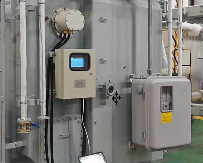
7.3 Composizione del sistema
Un completo sistema di monitoraggio della temperatura in fibra ottica fluorescente è costituito da cinque componenti chiave:
Demodulatore di temperatura in fibra ottica (Trasmettitore)

IL demodulatore di temperatura in fibra ottica è l'unità centrale di elaborazione del sistema. Genera impulsi luminosi di eccitazione, riceve il segnale fluorescente restituito, and computes the temperature value. Supporta un singolo demodulatore 1 A 64 canali di misura, making it suitable for monitoring multiple winding hot spots simultaneously. It provides an Interfaccia di comunicazione RS485 (ModbusRTU) per l'integrazione con DCS, SCADA, or transformer monitoring IEDs. All channel configurations and communication parameters are customizable per project requirements.
Fluorescent Fiber Optic Cable

IL fibra ottica fluorescente cable transmits excitation and return light between the demodulator and the sensing probe. It is fully dielectric, oil-resistant, and designed for long-term immersion in transformer insulating oil. The cable length is available from 0 A 20 meters to accommodate various transformer sizes and routing requirements.
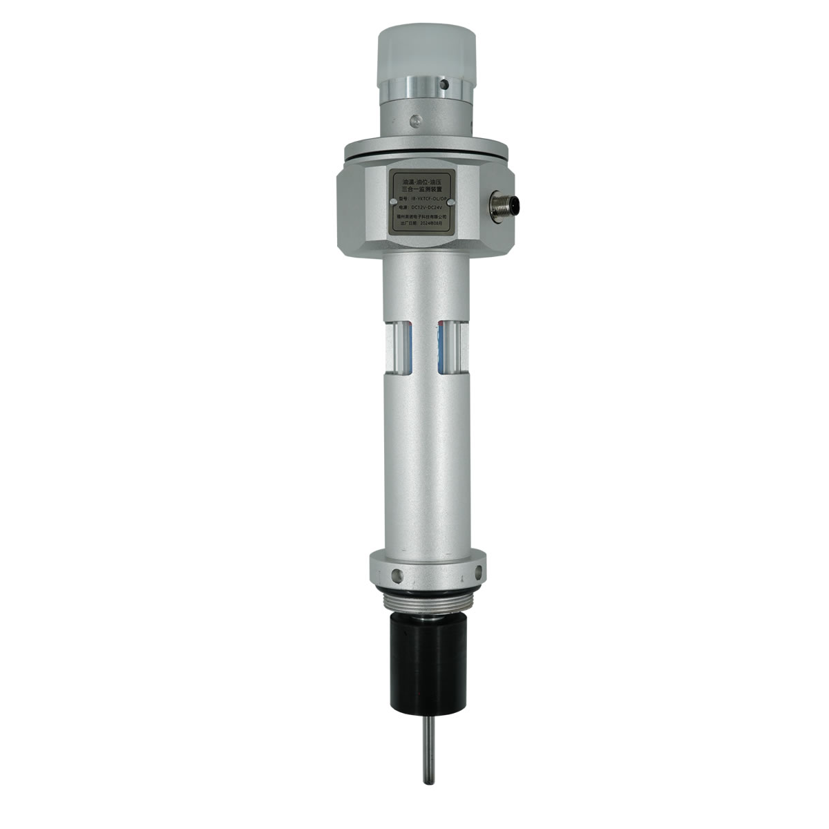
Sensing Probe
IL fluorescent temperature sensing probe contains the GaAs crystal and is the point of actual temperature measurement. The probe features a compact diameter of 2–3 mm and can be customized for specific installation requirements. It withstands continuous operating voltages exceeding 100 kV, making it fully qualified for direct placement against winding conductors in high-voltage and ultra-high-voltage transformers.
Modulo di visualizzazione
IL modulo di visualizzazione della temperatura provides local visual indication of all channel readings, stato di allarme, e diagnostica del sistema. It is typically panel-mounted on the transformer control cabinet.
Software di monitoraggio
IL temperature monitoring software runs on a connected PC or server and provides real-time trending, historical data logging, gestione degli allarmi, e generazione di report. It enables centralized remote monitoring of winding temperatures across multiple transformers.
7.4 Installation in Transformer Windings
IL sonda di rilevamento in fibra ottica fluorescente viene installato durante la produzione del trasformatore incorporandolo direttamente nel punto caldo calcolato all'interno della struttura dell'avvolgimento, tipicamente tra conduttori isolati nella parte superiore dell'avvolgimento ad alta o bassa tensione. IL cavo in fibra ottica viene fatto passare attraverso la struttura isolante ed esce dal trasformatore attraverso un raccordo passante in fibra ottica dedicato sulla parete del serbatoio. Perché l'intero sensore non è metallico e non conduttivo, non richiede uno speciale coordinamento dell’isolamento e non presenta alcun rischio per le prestazioni dielettriche del trasformatore.
8. Technical Comparison of All Four Methods
La tabella seguente fornisce un confronto completo e affiancato di tutti e quattro i metodi di monitoraggio della temperatura degli avvolgimenti del trasformatore discussi in questo articolo.
| Parametro | FATTO (Indicatore della temperatura dell'olio) | WTI (Indicatore della temperatura dell'avvolgimento) | Termocoppia / RST | Fibra ottica fluorescente (GaAs) |
|---|---|---|---|---|
| Tipo di misurazione | Indirect (oil only) | Indirect (simulazione termica) | Diretto (embedded) | Diretto (embedded) |
| Precisione | ±3–5°C | ±3–5°C | ±0,5–2,5°C | ±0,5–1°C |
| Intervallo di misurazione | 0–150°C | 0–200°C | Da −200 a +600°C | −40 to +260°C |
| Tempo di risposta | Several minutes | 5–15 minutes | 1–10 seconds | <1 secondo |
| Immunità EMI | Moderare | Moderare | Povero | Completare (all-dielectric) |
| Voltage Withstand | N / A (esterno) | N / A (esterno) | Limitato | >100 kV |
| Diametro della sonda | Bulb type | Bulb type | 3–6 mm | 2–3 mm (personalizzabile) |
| Materiale del sensore | Metallico | Metallico | Metallico | All-dielectric (insulating) |
| Cable/Fiber Length | 1–20 m | 1–20 m | Limitato dalla perdita di segnale | 0–20 m |
| Capacità del canale | Separare | Separare | Multipunto (wired) | 1–64 canali per demodulatore |
| Comunicazione | Contacts only (analogico) | Contacts only (analogico) | Analog signal / 4–20mA | RS485 (ModbusRTU), personalizzabile |
| Durata di servizio | 10–15 anni | 10–15 anni | 10–20 anni | >25 anni |
| Capacità di retrofit | Facile | Facile | Difficile | Factory installation recommended |
| Costo relativo | Basso | Basso-medio | Medio | Medium–High |
As shown in the table, IL sistema di monitoraggio della temperatura in fibra ottica fluorescente delivers the best combination of measurement accuracy, velocità di risposta, immunità elettromagnetica, dielectric safety, and long service life — making it the clear choice for critical power transformers where reliable winding temperature data is essential.
9. Casi applicativi globali

Fluorescent fiber optic winding temperature monitoring systems have been deployed in a wide range of transformer applications worldwide. The following are representative examples demonstrating proven performance across different voltage classes and operating environments.
9.1 High-Voltage Power Transformers (110 kV – 220 kV)
Multiple utility-class 110 kV and 220 kV power transformers in large-scale substation projects across Asia, il Medio Oriente, and South America have been equipped with sensori a fibra ottica fluorescente embedded at the calculated hot-spot locations. These installations enabled real-time winding temperature visibility and dynamic loading optimization, replacing older WTI-based thermal estimates.
9.2 Ultra-High-Voltage (UV) Transmission Transformers
In ultra-high-voltage transmission projects operating at 500 kV e superiori, the all-dielectric nature of the sonda di rilevamento in fibra ottica fluorescente is a critical advantage. These transformers demand absolute insulation integrity, and conventional metallic sensors are not acceptable. Fluorescent fiber optic systems have been successfully installed in multiple UHV transformer units, providing continuous hot-spot monitoring under extreme voltage stress.
9.3 Industrial and Traction Transformers
In applicazioni industriali come trasformatori di forni ad arco e trasformatori di trazione ferroviaria, profili di carico altamente variabili e ciclici rendono essenziale il monitoraggio accurato della temperatura degli avvolgimenti. Sistemi a fibre ottiche fluorescenti fornire il tempo di risposta veloce (<1 secondo) necessari per monitorare rapidi transitori termici, consentendo una protezione termica precisa in condizioni operative dinamiche.
9.4 Energie rinnovabili e trasformatori offshore
I trasformatori che servono parchi eolici e piattaforme offshore operano in ambienti difficili e remoti dove l'accesso per la manutenzione è limitato. Monitoraggio della temperatura in fibra ottica con accesso remoto ai dati tramite RS485 e integrazione SCADA consente agli operatori di gestire le prestazioni termiche senza visite fisiche in loco, riducendo significativamente il rischio operativo e i costi di manutenzione.
10. Winding Temperature Protection and Control Logic

Le misurazioni della temperatura degli avvolgimenti vengono utilizzate per guidare le azioni protettive e il controllo del raffreddamento. In un'implementazione tipica, il sistema di monitoraggio attiva le seguenti risposte in base a soglie di temperatura configurabili.
10.1 Attivazione del sistema di raffreddamento
Quando la temperatura dell'avvolgimento raggiunge la soglia del primo stadio (comunemente 85–95°C), il sistema di monitoraggio invia un comando per avviare ulteriori ventole di raffreddamento o pompe dell'olio. Questo attiva fasi di raffreddamento supplementari (PRIMO o PRIMO) per aumentare la capacità di dissipazione del calore.
10.2 Allarme
Una soglia di seconda fase (comunemente 105–110°C) attiva un allarme di alta temperatura, che viene annunciato localmente sul pannello di controllo del trasformatore e trasmesso in remoto al sistema SCADA per l'azione dell'operatore.
10.3 Viaggio
Se la temperatura continua a salire e raggiunge una soglia critica (comunemente 120–130°C), viene emesso un comando di sgancio per diseccitare il trasformatore e prevenire danni irreversibili all'isolamento. Questo segnale si interfaccia con il relè di protezione del trasformatore tramite contatti puliti o comunicazione digitale.
10.4 Integrazione SCADA e DCS
IL demodulatore di temperatura a fibra ottica fluorescente trasmette i dati della temperatura in tempo reale tramite RS485 (ModbusRTU) al sistema SCADA della sottostazione o al DCS dell'impianto. Ciò consente il monitoraggio centralizzato, andamento storico, e gestione termica coordinata su più trasformatori.
11. Ottieni una soluzione personalizzata
Ogni applicazione del trasformatore presenta requisiti unici per il numero di canali, percorso dei cavi in fibra, configurazione di visualizzazione, and system integration. Il nostro team di ingegneri presso FJINNO fornisce su misura fluorescent fiber optic temperature monitoring solutions per i produttori di trasformatori, utilità, e operatori industriali a livello mondiale.
Se hai bisogno di un sistema standard a 4 canali per un trasformatore di distribuzione o di una configurazione a 64 canali per un grande banco di trasformatori di potenza, forniamo pacchetti hardware e software completamente personalizzati con supporto tecnico completo.
Contattaci oggi to discuss your project requirements, request a quotation, or schedule a technical consultation. Visita www.fjinno.net for more information.
12. Domande frequenti (Domande frequenti)
Q1: What is the difference between oil temperature and winding temperature in a transformer?
Oil temperature represents the temperature of the insulating oil, typically measured at the top of the tank. Winding temperature is the actual temperature of the copper or aluminum conductor in the winding, which is always higher than the oil temperature due to the thermal gradient. The hot-spot winding temperature can be 20–40°C above the top-oil temperature under full load.
Q2: Why is a WTI not considered a direct measurement method?
A winding temperature indicator uses a thermal simulation approach. It estimates winding temperature by adding a current-dependent thermal contribution to the measured oil temperature. It does not have a sensor placed on the actual winding conductor, so it cannot capture the true hot-spot temperature under all operating conditions.
Q3: How does a fluorescent fiber optic sensor withstand high voltage inside a transformer?
The fluorescent fiber optic sensor is made entirely of non-metallic, dielectric materials — glass fiber and a GaAs crystal tip. It does not conduct electricity and therefore introduces no conductive path into the insulation structure. This allows it to operate safely at voltage levels exceeding 100 kV.
Q4: Can fluorescent fiber optic sensors be retrofitted into an existing transformer?
Fluorescent fiber optic sensors are most effectively installed during the transformer manufacturing process, quando possono essere posizionati con precisione nel punto caldo calcolato all'interno dell'avvolgimento. Retrofitting in un sigillato, il trasformatore riempito d'olio non è pratico senza rimuovere la parte attiva. Per trasformatori esistenti, Solitamente vengono utilizzati metodi WTI o di monitoraggio esterno.
Q5: Quanti punti di rilevamento può gestire un demodulatore?
Supporta un singolo demodulatore di temperatura in fibra ottica fluorescente 1 A 64 canali. Ciascun canale si collega a una sonda di rilevamento per la misurazione della temperatura di tipo puntiforme indipendente. Il conteggio dei canali è configurabile in base alle esigenze specifiche del progetto.
Q6: Quale protocollo di comunicazione utilizza il sistema?
L'interfaccia di comunicazione standard è RS485 utilizzando il protocollo Modbus RTU, che è ampiamente compatibile con i sistemi SCADA delle sottostazioni, Piattaforme DCS, e dispositivi elettronici intelligenti (IED). Altre opzioni di comunicazione possono essere personalizzate su richiesta.
D7: What is the expected service life of a fluorescent fiber optic temperature sensor?
The fluorescent fiber optic sensing probe and fiber cable are designed for a service life exceeding 25 anni, which matches or exceeds the typical design life of a power transformer. The all-glass construction and sealed GaAs crystal are resistant to degradation in transformer oil environments.
Q8: What international standards apply to transformer winding temperature limits?
The primary standards are IEC 60076-2 (temperature rise limits), CEI 60076-7 (guida al caricamento), IEEE Std C57.12.00 (general requirements), and IEEE Std C57.91 (loading and thermal modeling). These standards define maximum allowable winding rise temperatures and hot-spot limits for various loading conditions.
D9: Is the fluorescent fiber optic sensor affected by electromagnetic interference?
NO. Because the sensor is entirely non-metallic and the measurement principle is based on optical signals rather than electrical signals, it is completely immune to electromagnetic interference from the transformer’s magnetic field, transitori di commutazione, or nearby high-voltage equipment.
Q10: How do I determine the correct number of sensors needed for my transformer?
The number of sensing points depends on the transformer design, classe di tensione, tipo di raffreddamento, and the number of windings to be monitored. Tipicamente, sensors are placed at the calculated hot-spot locations of each major winding (alta tensione, LV, and tertiary if applicable). Our engineering team can assist with sensor placement planning based on the thermal design data of your specific transformer. Contattaci a www.fjinno.net for technical support.
13. Disclaimer
The information provided in this article is intended for general educational and reference purposes only. While every effort has been made to ensure the accuracy and reliability of the content at the time of publication, FJINNO makes no warranties or representations, espresso o implicito, per quanto riguarda la completezza, precisione, or suitability of the information for any specific application. Transformer design, installazione, and monitoring practices must comply with applicable local and international standards, regulations, and engineering best practices. Readers are advised to consult qualified engineers and refer to the latest editions of relevant standards before making any design or purchasing decisions. FJINNO shall not be liable for any direct, indiretto, or consequential damages arising from the use of or reliance on the information presented in this article. For project-specific technical guidance, please contact our engineering team at www.fjinno.net.

Sensore di temperatura a fibra ottica, Sistema di monitoraggio intelligente, Produttore di fibra ottica distribuito in Cina
|
 |
 |