 Sensori di temperatura a fibra ottica INNO ,sistemi di monitoraggio della temperatura.
- The Cost of Ignorance: Beyond the immediate replacement hardware costs, transformer failure consequences include massive production losses, regulatory environmental fines from oil spills, and critical safety hazards like arc flash explosions.
- Divergent Failure Paths: Mentre trasformatori in olio succumb to chemical sludge and moisture saturation, trasformatori a secco face distinct threats from epoxy resin cracking and air duct blockages caused by environmental contaminants.
- The Thermal Law: Asset life is strictly governed by the Arrhenius Law; a mere 6°C rise in winding hotspot temperature can halve the remaining useful life of the cellulose insulation, making precise thermal management non-negotiable.
- Blind Spots in Monitoring: Legacy methods like Top Oil temperature indicators and external Infrared thermography fail to provide visibility into the core. They suffer from thermal lag and cannot penetrate the tank wall to see the true internal state.
- The Optical Standard: Adopting Sensori di temperatura a fibra ottica fluorescente is the only method to achieve immune, diretto, and real-time monitoring of high-voltage windings, enabling safe dynamic loading and predictive intervention.
Sommario: Navigating Asset Health
- 1. What are the Severe Economic and Safety Consequences of Power Transformer Failure?
- 2. How Large are the Production Losses Caused by Unplanned Transformer Outages?
- 3. What are the Primary Insulation Failure Modes of Oil-Immersed Transformers?
- 4. How Can Resin Cracking and Air Duct Blockage be Prevented in Dry-Type Transformers?
- 5. How Does Short-Circuit Impact Cause Winding Deformation and Mechanical Damage?
- 6. How Does Moisture Intrusion Accelerate the Aging Process of Oil-Paper Insulation?
- 7. What Exactly is a Transformer Winding Hotspot and What Causes Its Formation?
- 8. How Does Temperature Rise Shorten Insulation Life According to Arrhenius Law?
- 9. How Does Transformer Overloading Trigger Internal Overheating Risks?
- 10. How Does Cooling System Failure Affect Overall Transformer Heat Dissipation Efficiency?
- 11. Why Can Top Oil Temperature Indicators Not Reflect the True Winding Temperature?
- 12. Can Infrared Thermography Cameras Penetrate the Tank to Detect Internal Winding Faults?
- 13. Why is Direct Winding Temperature Monitoring Critical for Fault Prevention?
- 14. What is the Working Principle of Fluorescent Fiber Optic Temperature Sensing Technology?
- 15. Why Does the High-Voltage Environment Require Anti-Electromagnetic Interference Temperature Sensors?
- 16. Are Fluorescent Fiber Optic Sensors Safe in High-Voltage Insulation Environments?
- 17. Does the Fluorescent Fiber Optic Temperature System Require Periodic Calibration and Maintenance?
- 18. How to Utilize Precise Temperature Data to Achieve Dynamic Transformer Rating Increases?
- 19. Can Existing Power Transformers be Retrofitted with Fiber Optic Temperature Systems?
- 20. Why Should You Deploy a Transformer Predictive Maintenance Solution Immediately?
1. What are the Severe Economic and Safety Consequences of Power Transformer Failure?

When a critical node in the electrical grid fails, the ripple effects extend far beyond the substation fence. The failure of a trasformatore di potenza is rarely a contained event; it is often a cascading catastrophe that impacts financial stability, human safety, e rispetto ambientale. Understanding the gravity of these consequences is the first step in justifying investment in advanced monitoring systems.
The Safety Imperative: Arc Flash and Explosion
The most immediate and terrifying consequence of a dielectric breakdown is the potential for an arc flash. When insulation fails under high voltage, the massive release of energy vaporizes the oil and copper, creating a rapidly expanding gas bubble. This pressure wave can rupture the steel tank in milliseconds. The combination of superheated oil and oxygen can lead to a fireball that endangers personnel and adjacent infrastructure. Predictive maintenance analytics aim to detect the precursors to this thermal runaway before the arc occurs.
Environmental Remediation Costs
Oil-filled transformers contain thousands of liters of insulating fluid. A tank rupture inevitably leads to leakage. If this oil seeps into the soil or local waterways, the utility faces substantial fines from environmental protection agencies (such as the EPA). The cost of specialized cleanup crews, soil excavation, and water purification often exceeds the cost of the transformer itself.
2. How Large are the Production Losses Caused by Unplanned Transformer Outages?
For utility operators and industrial facility managers, IL “costo totale di proprietà” calculation must include the risk of downtime. An unplanned outage is significantly more expensive than a planned maintenance window.
Calculating the Cost of Lost Production
In industrial applications such as steel mills, centri dati, or semiconductor manufacturing, a stable power supply is the lifeblood of operations. If a main step-down transformer fails unexpectedly, production stops instantly. Tuttavia, restarting complex industrial processes is not immediate. A 4-hour power outage might result in 48 hours of recalibration and wasted raw materials. Financial models show that for high-value industries, IL perdite di produzione can range from $10,000 oltre $1,000,000 per hour of downtime.
The Logistics of Emergency Replacement
Large power transformers are not off-the-shelf items. Lead times for new units can range from 6 A 18 mesi. While utilities keep spares, the logistics of transporting a 200-ton asset to a remote site, draining oil, and commissioning the new unit can take weeks. During this period, the grid may operate in a fragile N-0 state, risking blackouts for the wider region. Avanzato asset health management provides the necessary lead time to order replacements before the asset reaches its end of life.
3. What are the Primary Insulation Failure Modes of Oil-Immersed Transformers?
Trasformatori in olio rely on a complex synergy between the copper winding, the cellulose paper insulation, and the dielectric oil. This ecosystem is fragile. A failure in one component triggers a chemical chain reaction that destroys the others.
Sludge Formation and Thermal Blockage
As transformer oil oxidizes due to heat and oxygen exposure, it forms a semi-solid byproduct known as sludge. This sticky substance deposits onto the winding surfaces and inside the cooling radiator fins. The sludge acts as a thermal blanket, preventing the oil from removing heat from the copper. This creates a vicious cycle: the hotter the winding gets, the more sludge is produced, and the less efficient the cooling becomes. This is a primary cause of winding overheating.
Chemical Decomposition and Gas Generation
When oil and paper degrade, they release specific fault gases. Thermal faults (surriscaldamento) generate ethylene and ethane. High-energy electrical discharges generate acetylene. Without continuous monitoring, these gases accumulate until the dielectric strength of the oil drops below the stress threshold, resulting in a catastrophic short circuit.
4. How Can Resin Cracking and Air Duct Blockage be Prevented in Dry-Type Transformers?

Trasformatori a secco, particularly Cast Resin types, are favored for their fire safety in indoor environments. Tuttavia, they are not maintenance-free. Their failure modes are mechanical and environmental rather than chemical.
The Physics of Resin Cracking
The core coils are encapsulated in epoxy resin. The conductor (copper or aluminum) has a different coefficient of thermal expansion than the resin. When the transformer experiences rapid load changes—shifting from low load to peak load quickly—the conductor expands faster than the resin. Over repeated cycles, this mechanical stress causes micro-cracks in the insulation. These cracks become sites for scarico parziale, slowly eroding the insulation from the inside out until failure occurs.
Air Duct Blockage and Hotspots
Dry-type units rely on natural or forced air convection through cooling ducts between the coils. In industrial environments, these ducts can easily become clogged with dust, textile fibers, or other particulate matter. Unlike oil, which is pumped, air cannot circulate through a blocked duct. This results in localized temperature hotspots that are invisible to external fans. Continuous monitoring of the winding temperature is the only way to detect these blockages early, allowing for scheduled cleaning before the resin degrades.
5. How Does Short-Circuit Impact Cause Winding Deformation and Mechanical Damage?
While thermal issues are a slow killer, short circuits are violent events. UN short-circuit fault represents the ultimate mechanical stress test for a transformer. Understanding the electrodynamic forces at play is essential for diagnosing structural integrity issues that often precede electrical failure.
The Physics of Electrodynamic Forces
When a short circuit occurs on the secondary side, the current flowing through the windings can spike to 10 or even 20 times the rated nominal current. Secondo la legge delle forze di Lorentz, la forza meccanica esercitata sui conduttori è proporzionale al quadrato di questa corrente. Ciò significa che un aumento di corrente di 20 volte si traduce in un aumento di 400 volte della forza meccanica.
Queste forze agiscono in due direzioni principali:
- Forze radiali: Questi tendono a far scoppiare l'avvolgimento esterno (stress del cerchio) e schiacciare l'avvolgimento interno contro il nucleo (instabilità).
- Forze assiali: Questi tendono a spostare telescopicamente gli avvolgimenti, spesso danneggiando le strutture di bloccaggio e l'isolamento delle estremità.
L'effetto composto termo-meccanico
Il pericolo è aggravato dal caldo. Il massiccio aumento di corrente genera un riscaldamento resistivo immediato ($Io^2R$), ammorbidendo i conduttori di rame. Il rame ammorbidito è molto più suscettibile deformazione dell'avvolgimento. Even if the transformer survives the electrical fault, the resulting geometric distortion of the coils weakens the insulation layers, creating a “ticking time bomb” for future dielectric breakdown.
6. How Does Moisture Intrusion Accelerate the Aging Process of Oil-Paper Insulation?
Water is the arch-enemy of the oil-paper insulation system. Its presence is catalytic, meaning it not only reduces protection but actively accelerates the degradation of the cellulose chains that make up the solid insulation.
Sources of Moisture
Moisture enters the tank via two pathways:
- Atmospheric Ingress: Through leaky gaskets or poorly maintained silica gel breathers in free-breathing transformers.
- Internal Generation: As cellulose paper ages and degrades due to heat, water is a chemical byproduct of the decomposition process.
IL “Wet Paper” Conundrum
Moisture has a perverse affinity for the paper insulation. In a stable transformer, Sopra 98% of the moisture resides in the paper, non l'olio. Questa umidità abbassa il rigidità dielettrica dell'isolamento, aumentando significativamente il rischio di flashover. Inoltre, moisture acts as a catalyst for depolymerization. Wet paper ages significantly faster than dry paper at the same temperature. A moisture content increase from 1% A 2% can cut the insulation’s mechanical life in half.
7. What Exactly is a Transformer Winding Hotspot and What Causes Its Formation?
In transformer engineering, IL “average” temperature is a misleading metric. The life of the unit is determined by the temperature at the single hottest point within the insulation system—the winding hotspot.
Defining the Hotspot
The hotspot is typically located in the upper part of the windings, but its exact location is elusive. It is not simply a function of load current; it is a localized phenomenon caused by the concentration of losses.
Root Causes of Localized Heating
- Stray Flux Losses: Magnetic flux that escapes the core (leakage flux) induces eddy currents in the structural steel and the winding conductors themselves. These eddy currents generate additional heat that adds to the standard resistive losses.
- Oil Flow Stagnation: If the cooling oil ducts are narrow or blocked by sludge, the laminar flow of oil is disrupted. Without a fresh supply of cool oil, the heat in that specific pocket rises exponentially.
- Correnti armoniche: In modern grids filled with non-linear loads (solar inverters, VFD), high-frequency harmonics cause “skin effect” heating in the conductors, often creating hotspots that traditional thermal models fail to predict.
Detecting these elusive points requires direct winding temperature monitoring rather than estimation.
8. How Does Temperature Rise Shorten Insulation Life According to Arrhenius Law?
The relationship between temperature and transformer longevity is not linear; it is exponential. This relationship is described by the Arrhenius Law of chemical kinetics, which models the rate of chemical reaction (in this case, the depolymerization of cellulose).
La regola dei 6 gradi
Mentre gli standard variano leggermente (La regola di Montsinger suggerisce 6°C, L'IEEE cita spesso 6-8°C), la regola pratica per gli operatori dei servizi pubblici è rigida:
Per ogni aumento di 6°C della temperatura dell'hotspot al di sopra del limite nominale (solitamente 110°C), la vita residua dell'isolamento del trasformatore viene ridotta del 50%.
La reazione a catena di depolimerizzazione
La carta isolante è costituita da lunghe catene di molecole di glucosio. La lunghezza di queste catene è misurata come Degree of Polymerization (DP). La nuova carta ha un DP di circa 1000-1200. Quando il DP scende sotto 200, la carta diventa fragile e perde ogni resistenza meccanica.
Il calore eccessivo accelera la scissione di queste catene. Se un trasformatore funziona a 116°C anziché a 110°C per un periodo prolungato, sta invecchiando due volte più velocemente. Se funziona a 122°C, sta invecchiando quattro volte più velocemente. Questa certezza matematica sottolinea il motivo per cui il monitoraggio termico generico è insufficiente: pochi gradi di errore nella misurazione possono equivalere ad anni di vita persa delle risorse.
9. How Does Transformer Overloading Trigger Internal Overheating Risks?
Le società di servizi pubblici sono spesso costrette a utilizzare i trasformatori oltre i valori nominali indicati sulla targa a causa dei picchi di domanda o di scenari di emergenza N-1. Mentre sovraccarico del trasformatore a volte è necessario, comporta notevoli rischi termici che devono essere gestiti con precisione.
La fisica del riscaldamento da sovraccarico
La generazione di calore negli avvolgimenti è proporzionale al quadrato della corrente ($Io^2R$). UN 20% aumento del carico (1.2x corrente) risulta in a 44% aumento del riscaldamento resistivo ($1.2^2 = 1.44$). Questa rapida iniezione di energia termica può sopraffare la costante di tempo termica dell'olio di raffreddamento.
Formazione di bolle di gas
Il pericolo più immediato durante un grave sovraccarico non è solo l’invecchiamento, ma il “Effetto bolla.” Se la temperatura dell'avvolgimento supera i 140°C (a seconda del contenuto di umidità), il vapore acqueo intrappolato nella carta può trasformarsi in bolle di vapore. Queste bolle spostano l'olio isolante. Poiché il vapore ha una rigidità dielettrica molto inferiore rispetto all'olio, ciò può innescare un flashover interno immediato e un guasto catastrofico. Only monitoraggio degli hotspot in tempo reale può dare agli operatori la sicurezza necessaria per superare i limiti senza oltrepassare questa soglia mortale.
10. How Does Cooling System Failure Affect Overall Transformer Heat Dissipation Efficiency?
Il sistema di raffreddamento (radiatori, tifosi, e pompe) è il supporto vitale del trasformatore. Un degrado della sua efficienza è spesso il killer silenzioso che porta ad un invecchiamento termico prematuro.
Modalità comuni di guasto del raffreddamento
- Guasto della ventola: I ventilatori sono dispositivi meccanici soggetti al grippaggio dei cuscinetti e alla bruciatura del motore. Perdita di aria forzata (OFAF/ONAF) riduce significativamente il coefficiente di scambio termico.
- Blocco del radiatore: Detriti trasportati dall'aria, polline, and industrial dust can clog radiator fins, insulating them and preventing heat exchange with the ambient air.
- Pump Malfunction: In forced-oil systems, a pump failure stops the circulation of cool oil to the windings. The oil temperature at the top of the tank may appear stable, while the oil inside the winding ducts boils.
The Analytics of Cooling Efficiency
Avanzato transformer analytics can detect these failures by correlating load current with temperature rise. If the temperature rises faster than the theoretical model predicts for a given load, it is a clear signature of cooling system inefficiency.
11. Why Can Top Oil Temperature Indicators Not Reflect the True Winding Temperature?
Per decenni, the industry relied on the Top Oil Temperature thermometer as the primary gauge of health. Tuttavia, relying solely on this metric is a dangerous oversimplification.
The Problem of Thermal Lag
Insulating oil has a high specific heat capacity and a large thermal mass. It takes a long time to heat up. The copper windings, Tuttavia, have a low thermal mass and heat up almost instantly when load increases.
In a rapid overload scenario, the winding temperature might spike by 30°C in minutes, while the bulk oil temperature only rises by 2°C or 3°C. By the time the Top Oil indicator reflects the stress, the damage to the paper insulation has already occurred. This phenomenon is known as “thermal lag.”
The Inaccuracy of WTI Devices
Il tradizionale Indicatore della temperatura dell'avvolgimento (WTI) attempts to compensate for this by using a heating element fed by a current transformer (CT) to simulate the winding heat. This is an indirect simulation, not a measurement. Calibration errors, CT saturation, and environmental drift often render WTI readings inaccurate by ±10°C to ±15°C. In the context of the Arrhenius Law, an error of this magnitude makes accurate life assessment impossible.
12. Can Infrared Thermography Cameras Penetrate the Tank to Detect Internal Winding Faults?
Infrarossi (E) termografia is a valuable tool for substation maintenance, but its application for transformer diagnostics is frequently misunderstood.
Surface vs. Core Visibility
IR cameras detect infrared radiation emitted from the superficie of an object. They cannot see through steel tank walls or cast resin encapsulation. An IR scan can perfectly identify:
- Loose bushing connections.
- Overheating cooling fan motors.
- Low oil levels (by seeing the thermal gradient on the tank wall).
Tuttavia, an IR scan non può detect a hotspot deep within the HV winding layers caused by a blocked oil duct. The heat generated internally dissipates into the large volume of oil before it reaches the tank wall, creating a uniform surface temperature that masks the internal localized fault. Affidarsi all'IR per la salute degli avvolgimenti interni crea un falso senso di sicurezza.
13. Why is Direct Winding Temperature Monitoring Critical for Fault Prevention?
Date le limitazioni della simulazione indiretta (WTI) e scansione della superficie (E), l'industria si è spostata verso direct winding temperature monitoring (DWM). Questo approccio elimina le congetture dalla gestione patrimoniale.
The Value of “Verità fondamentale” Dati
Il monitoraggio diretto posiziona il sensore presso la fonte fisica del calore: i distanziatori degli avvolgimenti. Questo fornisce “verità fondamentale” dati con ritardo termico pari a zero. I benefici sono immediati:
- Validazione di modelli termici: Operators can compare real-time data against manufacturer heat-run test designs.
- Safe Emergency Overloading: During grid contingencies, operators can drive the transformer up to the exact thermal limit (per esempio., 130°C hotspot) without crossing into the danger zone of gas bubble formation.
- Optimized Cooling Control: Cooling banks can be triggered based on the winding temperature rather than oil temperature, ensuring fans run only when necessary, saving energy and extending fan motor life.
14. What is the Working Principle of Fluorescent Fiber Optic Temperature Sensing Technology?
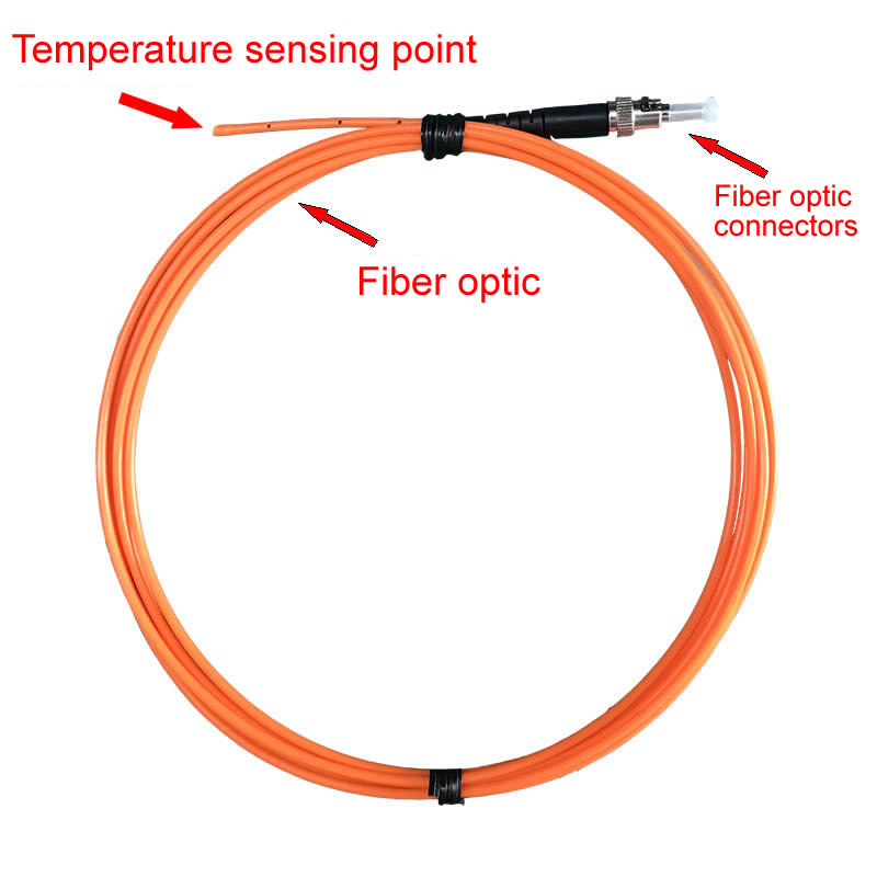
Among the various direct monitoring technologies, Fluorescent Fiber Optic Sensing has emerged as the gold standard due to its stability and simplicity.
The Science of Fluorescence Decay
The technology is based on the “Fluorescence Decay Time” principio.
1. An LED light source sends a pulse of blue light down a silica fiber optic cable.
2. This light excites a phosphor sensor material (tipicamente drogato con terre rare) sulla punta della sonda.
3. Il fosforo emette fluorescenza, emettendo una luce rossa.
4. Al termine dell'impulso di eccitazione, la luce rossa brillante decade (svanisce).
La proprietà fisica cruciale è questa la velocità di decadimento dipende perfettamente dalla temperatura. Le temperature più calde causano un decadimento più rapido; temperature più fredde causano un decadimento più lento. Misurando questa costante di tempo, il sistema calcola la temperatura con elevata precisione (tipicamente ±1°C).
15. Why Does the High-Voltage Environment Require Anti-Electromagnetic Interference Temperature Sensors?
The interior of a power transformer is one of the most hostile electromagnetic environments on earth. It contains high electric fields, high magnetic flux, and massive transient switching surges.
The Failure of Electronic Sensors
Conventional electronic sensors (termocoppie, RTD, or thermistors) require metal wires to transmit signals. In a transformer, these wires act as antennas. They pick up Interferenza elettromagnetica (EMI) e interferenze in radiofrequenza (RFI), resulting in noisy, unusable data. Worse, induced currents on these wires can heat the sensor itself, falsifying the reading.
The Optical Advantage
Sensori in fibra ottica are immune to EMI. They transmit light (fotoni), non elettricità (electrons). Light is unaffected by magnetic fields. This ensures that the temperature reading remains stable and accurate whether the transformer is at 10% load or experiencing a short-circuit fault current.
16. Are Fluorescent Fiber Optic Sensors Safe in High-Voltage Insulation Environments?

Safety is the paramount concern when introducing any foreign object into a high-voltage winding. The risk is that the sensor cable itself could become a path for electrical tracking (flashover).
Dielectric Integrity of the Sensor
Sonde a fibra ottica fluorescente are designed specifically for this challenge.
- Materiale: The fiber is made of high-purity quartz (silica glass), and the jacket is typically made of high-grade PTFE (Teflon) or PEEK. These are excellent electrical insulators.
- Creepage Distance: The materials are hydrophobic and resistant to oil absorption, preventing the formation of conductive paths along the cable surface.
- Partial Discharge Free: When properly installed in the winding spacers, these sensors do not distort the electric field and are tested to remain Partial Discharge (PD) free up to extremely high voltages (per esempio., 500classe kV).
This dielectric safety allows the sensor to be placed directly in contact with the high-voltage conductor, bridging the potential difference between the HV winding and the grounded tank wall safely.
17. Does the Fluorescent Fiber Optic Temperature System Require Periodic Calibration and Maintenance?
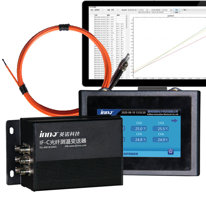
One of the most significant operational advantages of tecnologia delle fibre ottiche fluorescenti over older optical methods (such as GaAs or FBG) is its inherent stability.
No Calibration Drift
Older technologies relied on light intensity or wavelength shifts, which could be affected by fiber bending, perdite del connettore, o invecchiamento della sorgente luminosa. Al contrario, fluorescent technology measures tempo di decadimento. The decay characteristic of the phosphor sensor is a fundamental physical property of the material. It does not change over time, nor is it affected by the attenuation (dimming) of the fiber cable. Perciò, the system effectively requires no recalibration over its entire service life, making it a true “fit-and-forget” solution for long-term asset monitoring.
18. How to Utilize Precise Temperature Data to Achieve Dynamic Transformer Rating Increases?
The ultimate return on investment (ROI) for a predictive maintenance system lies in Dynamic Rating (or Dynamic Loading).
Unlocking Hidden Capacity
Nameplate ratings are conservative. They assume a worst-case scenario (per esempio., 40°C ambient temperature). Tuttavia, if the actual ambient temperature is 10°C, the transformer has significant thermal headroom. Con real-time winding temperature data, operators can safely load the transformer above its nameplate rating (per esempio., A 120% O 130%) during peak hours, provided the internal hotspot remains within safe limits. This delays the need for capital expenditure on new infrastructure by maximizing the utilization of existing assets.
19. Can Existing Power Transformers be Retrofitted with Fiber Optic Temperature Systems?
While the ideal time to install direct winding sensors is during the manufacturing process (winding phase), retrofitting is a viable option for critical legacy assets.
Retrofitting Strategies
- During Rewind/Refurbishment: If a transformer is sent to a repair shop for coil replacement, l'installazione delle sonde in fibra ottica nei distanziatori è una procedura di aggiornamento standard.
- Passaggi a parete del serbatoio: Per far uscire il segnale dal serbatoio, sono installate piastre passanti specializzate a tenuta d'olio. Questi possono spesso sostituire le piastre flangiate imbullonate non utilizzate sul coperchio o sulla parete del serbatoio.
- Sonde magnetiche esterne: Per unità che non possono essere aperte, le sonde in fibra ottica possono essere fissate magneticamente alla parete del serbatoio o ai collettori di raffreddamento per fornire immunità alle interferenze elettromagnetiche, sebbene ciò non fornisca visibilità diretta sull'avvolgimento.
20. Why Should You Deploy a Transformer Predictive Maintenance Solution Immediately?
La rete elettrica sta invecchiando, e i profili di carico stanno diventando più volatili con l’integrazione delle energie rinnovabili e della ricarica dei veicoli elettrici. IL “run-to-fallimento” approccio non è più economicamente sostenibile o sicuro. Implementare a predictive maintenance analytics La strategia incentrata sul monitoraggio ottico diretto trasforma la cultura della manutenzione da reattiva a proattiva.
By detecting thermal faults early, you prevent catastrophic failures, ensure the safety of your workforce, and secure the reliability of the power supply for your customers.
Beyond Transformers: Extended Applications of Our Fluorescent Fiber Optic Technology
Our advanced Fluorescent Fiber Optic Temperature Sensing System is not limited to power transformers. Its unique properties—total immunity to electromagnetic interference, high voltage isolation, and microwave transparency—make it the critical solution for a wide range of demanding industrial and medical applications.
Energia & Utility Sector
- Transformer Windings: Direct hotspot monitoring for Oil-Immersed and Dry-Type units.
- Quadro elettrico & Switchboards: Continuous monitoring of busbar joints, contatti, e terminazioni dei cavi.
- Large Hydro Turbines: Stator winding and bearing temperature monitoring in high-vibration environments.
- Terminazioni dei cavi & Heads: Online temperature monitoring for HV cable joints.
- Anello unità principali (RMU): Monitoraggio della temperatura della spina/boccola.
- Sistemi di sbarre isolate: Monitoraggio di percorsi conduttivi chiusi.
- Moduli IGBT: Gestione termica precisa per elettronica e inverter ad alta potenza.
- Circuit Breaker Static Contacts: Rilevamento di problemi di ossidazione e resistenza di contatto.
- GIS (Quadri isolati in gas): Rilevamento online degli hotspot all'interno delle camere a gas sigillate.
Medico & Ricerca scientifica
- Terapia con ipertermia RF: Monitoraggio della temperatura dei tessuti durante il trattamento del cancro senza interferire con i campi RF.
- Ablazione a microonde: Controllo preciso per procedure mediche basate su microonde.
- risonanza magnetica (Imaging a risonanza magnetica): Monitoraggio del paziente e dell'attrezzatura all'interno del foro altamente magnetico.
- RMN (Nuclear Magnetic Resonance): Compensazione della temperatura per spettrometri ad alta precisione.
Industriale & Produzione di semiconduttori
- Sistemi di incisione al plasma ICP: Controllo della temperatura dei wafer in campi di plasma ad alta energia.
- RIE (Reactive Ion Etching) Sistemi: Monitoraggio all'interno di mandrini elettrostatici.
- Microwave Digestion Systems: Monitoraggio della sicurezza per apparecchiature di analisi chimica.
- Riscaldamento industriale a microonde: Controllo del processo di essiccazione, curing, e applicazioni di sinterizzazione.
- Electro-Explosive Devices (EED): Testing and monitoring in volatile environments.
- High Energy Particle Physics: Monitoring in accelerators and synchrotrons where radiation and electromagnetic fields are extreme.
Ready to Secure Your Critical Assets?
Whether you are managing a fleet of high-voltage transformers or designing the next generation of MRI machines, accurate temperature data is your most valuable asset.
Contact our engineering team today to discuss your specific application requirements and discover how our Sensori a fibra ottica fluorescenti can provide the visibility you need.

Sensore di temperatura a fibra ottica, Sistema di monitoraggio intelligente, Produttore di fibra ottica distribuito in Cina
 |
 |
 |