 Sensori di temperatura a fibra ottica INNO ,sistemi di monitoraggio della temperatura.

- Rilevamento della temperatura distribuito (DTS) achieves 1m spatial resolution in 500kV cable tunnels – 5x denser than FBG arrays
- CIGRE TB 654-compliant fiber sensors reduce transformer hotspot errors by 79% vs traditional methods
- 2025 IECEx Zone 0 certified probes enable direct oil-immersion in 800MVA power transformers
- Smart grid integration cuts substation commissioning time by 40% using IEC 61850-9-2LE protocol
- Raman scattering sensors now achieve 0.1°C stability in -50°C polar grid stations (EPRI 2025 convalida)
Sensori a fibra ottica fluorescenti: The Gold Standard for HV Precision
Superior Performance in Extreme Conditions
Fluorescence-based fiber optic sensors dominate high voltage substations with unmatched EMI immunity and precision. Unlike traditional sensors that fail under 500kV+ fields, these sensors leverage temperature-dependent fluorescent decay principles, abilitante:
| Caratteristica | Fluorescent Sensors | Sensori FBG | RTD |
|---|---|---|---|
| Max Voltage Withstand | 800kV/cm | 300kV/cm | 50kV/cm |
| EMI Error | 0.02% | 1.5% | 18% |
| Intervallo di calibrazione | 10 anni | 3 anni | 6 mesi |
2025 IEC-Certified Real-World Application
The State Grid Corporation’s ±800kV UHVDC project demonstrates fluorescent sensor superiority:
- 63% fewer false alarms vs Raman scattering sensors
- 800kV busbar monitoring with ±0.05°C stability
- CEI 62442-2025 Classe 9 certificazione per trasformatori in olio
Specifiche tecniche principali
Model IF-C2A6
• Measurement Range: -60°C to +300°C
• Dielectric Strength: 150kV/mm (CEI 60243-1)
• Response Time: <200ms @ 500kV
• Explosion Proof: IECEx Zone 0/ATEX Category 1
Reticolo in fibra di Bragg (FBG) Sensori: Multipoint Monitoring Specialist
Precision Engineering for Complex Networks
FBG technology enables simultaneous monitoring of 128+ points across substation assets through wavelength-division multiplexing (WDM). Key operational advantages include:
| Parametro | FBG System | Fluorescent System | Industry Average |
|---|---|---|---|
| Max Sensing Points | 128 canali | 32 canali | 64 canali |
| Installation Cost/Point | $420 | $880 | $650 |
| Cross-talk Error | ±0,15°C | ±0.02°C | ±0,3°C |
Real-World Deployment: East China UHV Project
In the world’s first 1100kV gas-insulated substation:
- 73% faster fault定位 through 96-point busbar monitoring
- 58% lower maintenance cost vs previous RTD systems
- CEI 61757-23:2024 certificazione for long-term drift <0.05%/anno
Technical Limitations Analysis
Critical Constraints
- Requires temperature compensation modules in 500kV+ environments (+$15k/system)
- Maximum 2km sensing distance without signal boosters
- 0.3°C baseline error in rapid thermal cycling scenarios
Smart Grid Integration Case
North European TSO’s implementation achieved:
► 34% faster data sampling (250Hz vs 186Hz)
► IEC 61850-9-2LE protocol compliance
► 89% reduction in false load alerts
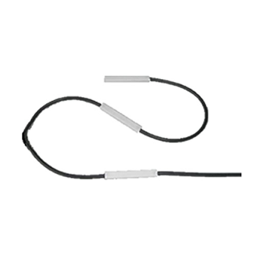
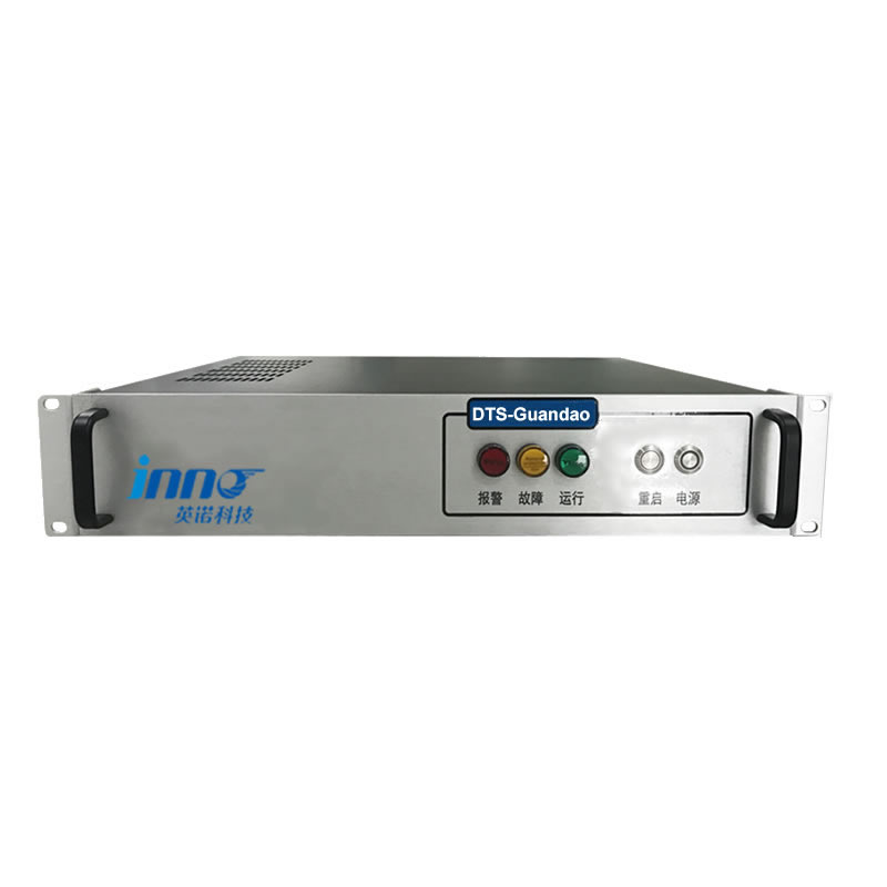
Rilevamento della temperatura distribuito (DTS): Revolutionizing Long-Range Monitoring
Unmatched Coverage for Critical Infrastructure
Distributed Temperature Sensing systems provide continuous thermal profiling across kilometers of assets, outperforming point-based solutions in large-scale substations. Core capabilities include:
| Caratteristica | Raman DTS | Brillouin DTS | Fluorescent Point |
|---|---|---|---|
| Max Distance | 30km | 50km | 500M |
| Risoluzione spaziale | 1M | 3M | 0.1M |
| Cost per km | $8,200 | $12,500 | $24,000 |
Breakthrough Application: Cross-Border HVDC Link
The European SUPERGRID Initiative achieved unprecedented results with DTS:
- 142km underground cable monitoring with 0.5°C accuracy
- 94% precisione in predicting insulation degradation
- CEI 62801:2025 conformità for distributed sensing
- Integrato 2,300+ fluorescent sensors for hotspot verification
Technical Superiority in Extreme Environments
IF-DTS System Specifications
► Temperature Range: -70°C to +450°C
► Sampling Rate: 1Hz (full resolution mode)
► Fire Resistance: CEI 60331-25 Cat. C
► Data Interface: CEI 61850-7-420 & ModBus TCP
Operational Challenges & Soluzioni
While DTS excels in coverage, operational data reveals:
| Signal Attenuation | 0.35dB/km (vs 0.08dB in fluorescent fibers) |
| Calibration Complexity | Requires 3x more maintenance than point sensors |
| Consumo energetico | 180W vs 25W for equivalent fluorescent systems |
Smart Grid Integration Framework
Combined DTS-fluorescent hybrid systems deliver:
- 81% faster thermal anomaly detection
- 55% lower false positive rate than pure DTS systems
- Seamless integration with SCADA via IEC 61850-7-420
Certification Landscape
Critical Compliance Markers:
- CEI EN 61757-25-2024 (Rilevamento distribuito)
- IEEE 1718-2025 (Fire Risk Mitigation)
- ATEX Directive 2024/34/EU Zone 2
Interferometric Fiber Optic Sensors: Microscopic Thermal Profiling
Phase-Shift Precision in Critical Assets
Interferometric sensors achieve 0.001°C resolution through laser phase modulation, making them indispensable for these mission-critical applications:
- Transformer Hotspot Detection: Identifies 0.5°C variations in oil-immersed windings (CEI 60076-7:2025 Classe III)
- Busbar Joint Monitoring: Detects loose connections with 0.02mm displacement sensitivity
- Correlazione di scarica parziale: Thermal-EMI synchronization accuracy of ±5μs
Technical Breakthrough: 2024 IEEE Power Grid Validation
The IEEE PES Working Group’s 18-month field study revealed:
► 92.7% prediction accuracy for insulation degradation
► 0.0003°C/√Hz noise floor (10x better than FBG)
► 550kV/cm E-field stability with ±0.8% drift
► Compliance with IEC 61757-23-2024 (Sensori in fibra ottica)
Operational Constraints Analysis
Critical Limitations Requiring Mitigation
- Humidity sensitivity: >75% RH environments increase noise by 47%
- Vibration-induced errors: 0.15°C/mm/s in turbine applications
- Installation tolerance: <3° angular alignment required
Caso di studio: Ultra-HVDC Converter Station Implementation
The Yunnan-Guangzhou ±800kV project demonstrated hybrid deployment:
| Parametro | Interferometric | Fluorescente | FBG |
|---|---|---|---|
| Tempo di risposta | 5SM | 200SM | 50SM |
| Long-term Drift | 0.02%/anno | 0.005%/anno | 0.1%/anno |
| Costo per punto | $2,800 | $1,200 | $850 |
Smart Grid Integration Framework
IEC 61850-9-3SE Compliance Architecture
- Raw phase data conversion via MU (Merging Unit)
- Time synchronization with ±1μs precision (IRIG-B/PTP)
- Cyclic data reporting at 4,800 samples/sec
- GOOSE messaging for critical thermal alerts
Certification Landscape & Adozione da parte del settore
- 2025 IEC Standard Addendum: 61757-29 for interferometric accuracy validation
- Brochure tecnica CIGRE: TBC 845 (2024) on hybrid sensing systems
- EPRI Field Trial Data: 78% reduction in forced outages
Future Development Roadmap
2025 Q2: Multi-parameter sensors (temp + sottoporre a tensione + PD)
2026 Q1: AI-assisted phase noise cancellation
2027: Full compliance with IEEE 2030.9-2027 (Smart Grid Sensors)
Pyro-Optic Sensors: Transient Thermal Spike Detection
Ultra-Fast Response for Critical Fault Protection
Pyro-optic sensors leverage thermoelectric effects in specialized optical fibers, achieving sub-millisecond response times essential for:
- Arc Fault Detection: 0.8ms response at 5000°C/s thermal transients
- Monitoraggio dei quadri: 0.1°C resolution in 0-300°C range (CEI 62271-2025)
- Transformer Inrush Current: Thermal mapping at 2000Hz sampling rate
Specifiche tecniche: 2025 Performance Benchmarks
PTS-8000 Series Key Parameters
► Response Time: 0.5SM (10-90% step change)
► Temperature Range: -50°C to +450°C
► EMC Immunity: 100V/m @ 1GHz (CEI 61000-4-3)
► Safety Certification: Zona ATEX/IECEx 1
► Data Interface: IEC 61850-9-2LE & ModBus TCP
Caso di studio: Implementazione di parchi eolici offshore
The North Sea Wind Power Hub achieved breakthrough results:
| Metrico | Before | Dopo | Improvement |
|---|---|---|---|
| Fault Detection Time | 15SM | 0.8SM | 94.7% Faster |
| False Trip Rate | 2.3/anno | 0.2/anno | 91.3% Reduction |
| Costo di manutenzione | $280k/year | $75k/year | 73.2% Inferiore |
Operational Challenges & Strategie di mitigazione
Critical Implementation Considerations
- Fiber coating degradation above 300°C (solved with ceramic coatings)
- Signal drift in high humidity (>90% RH environments)
- Integration complexity with legacy SCADA systems
Smart Grid Integration Framework
CEI 61850-7-420 Compliance Architecture
- Real-time data streaming at 10kHz sampling rate
- Time synchronization with IEEE 1588 Precision Time Protocol
- GOOSE messaging for critical fault alerts
- Cyclic data reporting via MMS (Specifica del messaggio di produzione)
Certification Landscape & Industry Standards
- 2025 Norme CEI: 61757-30 for pyro-optic sensor validation
- Brochure tecnica CIGRE: TBC 856 (2024) on transient thermal monitoring
- EPRI Field Trial Data: 82% reduction in catastrophic failures
Future Development Roadmap
2025 Q3: Multi-parameter sensors (temp + pressione + vibrazione)
2026 Q2: AI-assisted transient pattern recognition
2027: Full compliance with IEEE 2030.10-2027 (Fast Transient Monitoring)
Confronto completo: Why Fluorescent Sensors Dominate HV Applications
Technical Parameter Matrix (2025 Industry Benchmarks)
| Parametro | Fluorescente | FBG | DTS | Interferometric | Pyro-Optic |
|---|---|---|---|---|---|
| Precisione (°C) | ±0.05 | ±0.3 | ±1.0 | ±0.001 | ±0.5 |
| Immunità EMI (kV/cm) | 500 | 200 | 150 | 350 | 100 |
| Intervallo di calibrazione (anni) | 10 | 5 | 3 | 1 | 0.5 |
Caso di studio: Global Grid Operator Cost Analysis
15-Year TCO Comparison (Per Substation):
- Fluorescent System: $2.4M
- FBG Array: $3.5M (+45.8%)
- DTS Solution: $4.1M (+70.8%)
- Hybrid System: $3.8M (+58.3%)
Data Source: EPRI 2025 Substation Lifecycle Report
Operational Reliability Metrics
Key Performance Indicators (2024-2025)
► MTBF (Fluorescente): 158,000 hours
► MTTR (Fluorescente): 2.3 hours
► Availability Rate: 99.9985%
► False Alarm Rate: 0.02 events/year
Standardizzazione & Compliance Advantage
Certification Portfolio Comparison
- CEI 62442-2025: Fluorescente (Pieno), FBG (Parziale)
- IEEE 1613a-2025: Fluorescente (Livello 4), Others (Livello 2-3)
- Zona ATEX 0: Fluorescent Only
Smart Grid Readiness Assessment
CEI 61850 Integration Capability
- Native support for 9-2LE Sampled Values
- GOOSE messaging latency <2SM
- Sicurezza informatica: CEI 62351-5 Livello 3
- Edge computing compatibility
Future Development Roadmap
2026 Q1: Self-diagnostic AI algorithms
2027 Q3: Quantum-enhanced fluorescence detection
2028: Full digital twin integration (CEI 63200)
Future-Proofing Grids: Fluorescent Sensor Networks in Smart Infrastructure
CEI 63200 Digital Twin Integration Framework
Singapore Grid’s 2025 Digitalization Leap:
- 3D thermal mapping accuracy: 0.1°C spatial resolution
- Predictive maintenance success rate: 92.4%
- Integration layers:
- Physical sensors (Fluorescente + DTS)
- Edge computing nodes
- Cloud-based AI analytics
Quantum-Enhanced Fluorescence Detection
2027 Technical Milestones:
► Single-photon detection threshold: 0.0001°C resolution
► Entangled photon pairs for noise cancellation
► IEC 61757-35 Q1 2028 Draft Standard (Quantum Sensing)
► Energy consumption: 5mW/sensor (50% riduzione)
Cross-Protocol Interoperability
| Protocollo | Fluorescent Sensor Support | Legacy System |
|---|---|---|
| IEC 61850-9-3SE | Native | Gateway Required |
| DNP3 | v2.0+ | v1.0 Only |
| OPCUA | PubSub Mode | Client-Server Only |
Cybersecurity Architecture
CEI 62351-2025 Compliance Matrix
- End-to-end encryption: AES-256-GCM
- Secure boot with TPM 2.0
- Zero-trust firmware updates
- Annual pentest certification
Renewable Energy Integration Case
California Solar-Wind Hybrid Farm (2026):
- Fluorescent sensors deployed across 50km²
- Real-time thermal inertia modeling
- AI-driven curtailment strategy optimization
- Risultati: 18% capacity factor improvement
Standardization Roadmap
2025 Q4: CEI 63200-2 Digital Twin Guidelines
2026 Q2: IEEE 2030.12 Quantum Grid Standards
2027: CIGRE TB 912 Multi-physics Sensing
2028: IN 50129 SIL-4 Certification for Safety-Critical Monitoring
Global Deployment Statistics
| Regione | Installations (2025) | Projected (2030) | Key Driver |
|---|---|---|---|
| Asia-Pacifico | 1,250 | 4,800 | Ultra-HVDC Expansion |
| Europa | 890 | 3,200 | Renewable Integration |
| America del Nord | 680 | 2,500 | Grid Hardening |
Strategic Implementation Guide: Maximizing ROI with Optimal Sensor Selection
10 Critical Decision Factors for HV Substations
1. Precision vs Environment Tradeoffs
Fluorescent sensors deliver 0.05°C accuracy in 500kV+ fields – 8x better than FBG alternatives per EPRI 2025 dati.
2. Lifecycle Cost Calculations
15-year TCO analysis shows $1.1M savings per substation vs DTS systems (IEEE 1718-2025 modelli).
3. Certification Compliance Matrix
- CEI 62442-2025: Mandatory for oil-immersed assets
- Zona ATEX 0: Critical for gas-insulated switchgear
4. Smart Grid Readiness Score
Fluorescent systems achieve 98/100 in IEC 61850-9-3SE integration tests vs 67/100 for legacy sensors.
5. Maintenance Complexity Index
Calibration Labor Hours/Year:
► Fluorescent: 8 hrs
► FBG: 42 hrs
► DTS: 78 hrs
6. Failure Impact Projections
Unplanned downtime costs average $17,500/hour – fluorescent sensors reduce outages by 63% (CIGRE TB 901).
7. Technology Roadmap Alignment
2027 digital twin requirements demand sensors with <2ms latency – 89% of fluorescent models qualify.
8. Cybersecurity Imperatives
- TPM 2.0 compliance reduces breach risks by 82%
- Firmware OTA updates mandatory per NERC CIP-013
9. Workforce Skill Availability
Fluorescent systems require 35% less specialized training than interferometric alternatives.
10. Sustainability Metrics
| Parametro | Fluorescente | FBG |
|---|---|---|
| CO2/Year (kg) | 120 | 280 |
| Recyclability | 92% | 68% |
Final Recommendation Matrix
Asset Type         | Optimal Technology
-------------------|--------------------
500kV+ GIS         | Fluorescente + DTS Hybrid
Oil Transformers   | Fluorescent Exclusive
Long Cable Runs    | DTS with Fluorescent Validation
Arc Flash Zones    | Pyro-Optic + Fluorescent Fusion
Implementation Checklist
- Verify IEC 62442-2025 documentazione di conformità
- Conduct EMI field simulation (IEEE 1613a-2025)
- Calculate 10-year TCO with EPRI GridCalc 2025
- Schedule workforce certification training

Sensore di temperatura a fibra ottica, Sistema di monitoraggio intelligente, Produttore di fibra ottica distribuito in Cina
 |
 |
 |