 INNO फाइबर ऑप्टिक तापमान सेंसर ,तापमान निगरानी प्रणाली.
Core Advantages of Transformer Fiber Optic Temperature Monitoring Systems
- Complete Immunity to Electromagnetic Interference: फ्लोरोसेंट फाइबर ऑप्टिक सेंसर use pure optical signal transmission with no metal or electronic components, enabling stable operation in 110kV to 500kV ultra-high voltage transformer electromagnetic environments, unaffected by lightning, switching operations, or short-circuit current transients.
- Direct Hot Spot Temperature Measurement: फाइबर ऑप्टिक जांच with diameters of only 1-3mm can be directly embedded between oil-filled transformer winding layers or inside dry-type transformer coils, measuring true hot spot temperatures rather than calculated estimates, with measurement accuracy of ±1°C and response time under 1 दूसरा.
- Extended Service Life with Zero Maintenance: फ्लोरोसेंट फाइबर ऑप्टिक तापमान सेंसर are passive, बहाव-मुक्त, and aging-resistant, capable of continuous operation in transformer oil for over 30 years without calibration or replacement, with fiber transmission distances of 0-80 meters perfectly matching the wiring distance from transformer body to control room.
- Multi-Point Monitoring with Single System: एक भी फाइबर ऑप्टिक तापमान माप प्रणाली can simultaneously connect 1-64 channels of fluorescent fiber optic sensors, monitoring all critical locations including three-phase winding hot spots, top oil temperature, निचला तेल तापमान, and core temperature for comprehensive transformer temperature surveillance.
- Wide Temperature Range for All Transformer Types: फ्लोरोसेंट फाइबर ऑप्टिक तापमान माप ranges from -40°C to +260°C, suitable for monitoring oil-filled transformer normal operating temperatures (-25°C to +105°C), dry-type transformer high-temperature conditions (up to 180°C), and even extreme temperatures during overload and fault conditions.
- Prevention of Insulation Aging and Thermal Breakdown: Real-time monitoring enables the system to trigger alarms before winding temperature exceeds insulation material temperature limits (oil-filled 98-110°C, dry-type 155-180°C). According to Montsinger’s 6-degree rule, reducing temperature by 6°C doubles insulation lifespan, extending transformer life from 20 to over 40 साल.
- Multi-Level Alarms and Intelligent Interlocking Control: The system provides three-level protection including temperature pre-warning, उच्च तापमान अलार्म, and over-temperature trip, automatically starting/stopping cooling fans/oil pumps, switching tap changers to reduce voltage, and sending remote alarm signals to SCADA systems for unmanned substation automation.
- Wide Applications Across Power and Industrial Sectors: Beyond transformer monitoring, the same technology platform applies to switchgear contact temperature measurement, power cable joint monitoring, generator stator temperature measurement, medical MRI equipment, high-temperature industrial furnaces, and other scenarios requiring electromagnetic interference immunity or insulated temperature measurement.
विषयसूची
- What is a Transformer Fiber Optic Temperature Monitoring System?
- Why is Transformer Winding Hot Spot Temperature Monitoring Critical?
- What Are the Fundamental Differences Between Fiber Optic Temperature Sensors and Traditional PT100/Thermocouples?
- How Do Temperature Monitoring Requirements Differ Between Oil-Filled and Dry-Type Transformers?
- फ्लोरोसेंट, डीसीएफ, and GaAs Fiber Optic Temperature Measurement Technologies Compared: Why Fluorescent is Best for Transformers
- How Do Fluorescent Fiber Optic Temperature Sensors Work?
- Why Does Fluorescent Fiber Optic Temperature Measurement Achieve Complete EMI Immunity?
- What is a Transformer Winding Hot Spot? Where is it Located and Why is it Dangerous?
- How Are Fiber Optic Temperature Probes Installed at Transformer Winding Hot Spots?
- What is the Difference Between Distributed Temperature Sensing (डीटीएस) and Point Fluorescent Fiber Optic Temperature Sensors?
- What is the Typical Configuration for Oil-Filled Transformer Fiber Optic Monitoring Systems?
- What is the Installation Solution for Dry-Type Transformer Fiber Optic Temperature Measurement Systems?
- What is the Role of Transformer Oil and How Does Temperature Affect Its Insulation and Cooling Performance?
- How Does the Fiber Optic Monitoring System Interlock with Transformer Cooling Systems and Load Tap Changers?
- How Does the System Implement Multi-Level Temperature Alarms and Trip Protection for Transformers?
- शीर्ष 10 वैश्विक ट्रांसफार्मर फाइबर ऑप्टिक तापमान सेंसर निर्माता
- Why is FJINNO Considered the Best Choice for Transformer Fiber Optic Temperature Monitoring Systems?
- How to Select Appropriate Optical Temperature Sensor Systems for Different Transformer Capacities and Voltage Levels?
- What Are the Hazards of Transformer Overload Operation and How Does Fiber Optic Temperature Measurement Provide Protection?
- What Are the Main Causes of Abnormal Transformer Temperature Rise and Hot Spot Temperature Exceedance?
- How to Identify Internal Transformer Fault Types Through Fiber Optic Thermometer Temperature Curves?
- What Are the Rated Temperature Rise and Allowable Temperatures for Transformers According to International Standards?
- Which International Standards (IEC/IEEE) Must Transformer Fiber Optic Temperature Monitoring Systems Comply With?
- What is the Integration Solution for Optical Temperature Sensors in Smart Substations?
- How to Obtain Customized Transformer Fiber Optic Temperature Monitoring Solutions and Bulk Procurement Quotes?
1. क्या है एक Transformer Fiber Optic Temperature Monitoring System?
ए Transformer Fiber Optic Temperature Monitoring System is a specialized real-time temperature surveillance device designed for power transformers, का उपयोग करते हुए फाइबर ऑप्टिक तापमान सेंसर to directly measure temperatures at critical transformer locations and performing data acquisition, विश्लेषण, and alarming through fiber optic temperature measurement hosts.
The system’s core is the फ्लोरोसेंट फाइबर ऑप्टिक तापमान सेंसर, a point-type temperature measurement technology based on rare earth material fluorescence lifetime principles. Unlike traditional resistance or thermocouple thermometers, फाइबर ऑप्टिक थर्मामीटर utilize purely optical signal transmission requiring no electrical power supply, enabling stable operation in high-voltage, strong electromagnetic field environments.
For oil-filled transformers, the system monitors critical temperature points including three-phase winding hot spots, top oil temperature, and bottom oil temperature. शुष्क प्रकार के ट्रांसफार्मर के लिए, it focuses on three-phase winding temperature distribution (आम तौर पर 2-3 measurement points per phase).
आधुनिक फाइबर ऑप्टिक तापमान माप प्रणाली not only provide real-time temperature display but also feature historical data recording, तापमान प्रवृत्ति विश्लेषण, over-temperature alarming, remote communication (मोडबस/आईईसी 61850), making them fundamental tools for transformer condition monitoring and asset health management.
Five Critical Functions of Transformer Winding Hot Spot Temperature Monitoring:
Preventing Insulation Thermal Breakdown
When winding hot spot temperatures exceed insulation paper or epoxy resin temperature limits (typically 98-110°C for oil-filled, 155-180°C for dry-type), insulation strength drops sharply. Fiber optic monitoring can trigger alarms or load reduction commands before temperatures reach dangerous thresholds.
Extending Transformer Service Life
According to the Arrhenius equation, insulation material aging rate increases exponentially with temperature. The Montsinger 6-degree rule states that insulation lifespan doubles for every 6°C temperature reduction. सटीक फाइबर ऑप्टिक तापमान माप maintaining winding temperatures within optimal ranges can extend transformer life from 20 years to over 40 साल.
Enabling Dynamic Load Management
Traditional transformers operate at fixed rated capacity. With real-time hot spot monitoring through ऑप्टिकल तापमान सेंसर, operators can safely increase loads during cool seasons or low-load periods while reducing loads during summer peaks or high ambient temperatures, optimizing asset utilization without compromising safety.
Early Fault Detection and Diagnosis
Abnormal temperature rise patterns can reveal internal faults: sudden single-phase temperature rise may indicate winding short circuits, three-phase unbalanced temperature rise suggests core lamination short circuits, and gradual overall temperature rise indicates cooling system failure. फाइबर ऑप्टिक तापमान सेंसर उपलब्ध करवाना 24/7 data for predictive maintenance.
Meeting Smart Grid and Regulatory Requirements
आईईसी 60076-7 and IEEE C57.91 standards recommend installing फाइबर ऑप्टिक तापमान की निगरानी systems on transformers above 10MVA. Modern smart substations require transformers to upload real-time temperature data to SCADA/EMS systems, साथ fiber optic measurement systems seamlessly integrating through IEC 61850 प्रोटोकॉल.
2. Why is Transformer Winding Hot Spot Temperature Monitoring Critical?
Transformer winding hot spot temperature is the highest temperature point within the entire transformer, typically located at the innermost turns of the high-voltage winding or areas with concentrated stray losses. This single point’s temperature directly determines transformer insulation lifespan and operational safety.
Unlike top oil temperature or average winding temperature that can be indirectly measured or calculated, hot spot temperature can only be accurately obtained through direct measurement with फाइबर ऑप्टिक तापमान सेंसर. Traditional winding temperature indicators (डब्ल्यूटीआई) estimate hot spot temperature by adding a calculated gradient to top oil temperature, with errors potentially reaching 10-20°C, making them unsuitable for precision thermal management.
Why Hot Spot Temperature is More Critical Than Top Oil Temperature:
Localized Nature of Insulation Failure
Transformer insulation failure is always a localized phenomenon. Even if 99% of the winding maintains normal temperature, a single hot spot exceeding limits can cause insulation breakdown, शॉर्ट सर्किट, and catastrophic failure. Top oil temperature reflects only average heat generation and cannot reveal localized overheating.
Non-Linear Insulation Aging Process
Cellulose insulation paper aging follows exponential laws. 110°C पर, lifespan is approximately 20 साल; at 120°C, it drops to 5 साल; at 140°C, केवल 6 months remain. A 10°C hot spot temperature difference can mean a 4-fold lifespan variance, making precise फाइबर ऑप्टिक तापमान माप economically crucial.
Rapid Thermal Runaway Characteristics
When hot spot temperatures exceed critical points, insulation resistance drops, increasing leakage current, generating more heat, and creating positive feedback leading to thermal runaway. This process can accelerate from normal to failure within hours. Only real-time फाइबर ऑप्टिक निगरानी with sub-second response can provide timely warnings.
Load Capacity Determination Basis
According to IEEE C57.91 standard, transformer allowable overload capacity is determined by hot spot temperature rather than top oil or ambient temperature. Without direct hot spot measurement through ऑप्टिकल तापमान सेंसर, operators must apply conservative margins, wasting transformer capacity.
Different Temperature Limits for Different Transformer Types
Oil-filled transformer hot spots must not exceed 98°C (normal) or 110°C (आपातकाल), while dry-type transformers allow 130-180°C depending on insulation class. Without direct measurement via फाइबर ऑप्टिक तापमान सेंसर, it’s impossible to verify compliance with these limits.
3. What Are the Fundamental Differences Between फाइबर ऑप्टिक तापमान सेंसर and Traditional PT100/Thermocouples?

Traditional electrical temperature sensors (PT100 प्लैटिनम प्रतिरोध, K-type thermocouples) and modern फाइबर ऑप्टिक तापमान सेंसर represent fundamentally different measurement principles, with performance differences particularly pronounced in transformer applications.
| तुलना पैरामीटर | फ्लोरोसेंट फाइबर ऑप्टिक तापमान सेंसर | PT100 Platinum Resistance | K-Type Thermocouple |
|---|---|---|---|
| काम के सिद्धांत | Rare earth fluorescence lifetime temperature dependence | Platinum resistance temperature coefficient | Seebeck thermoelectric effect |
| Signal Transmission | Optical signal (completely non-conductive) | Electrical signal (4-20mA/resistance) | Electrical signal (millivolt level) |
| ईएमआई प्रतिरक्षा | पूर्ण प्रतिरक्षा (no metal components) | Severely affected (requires shielding) | Severely affected (magnetic field interference) |
| High Voltage Insulation | Inherent insulation (optical fiber is insulator) | Requires complex insulation structure | Requires complex insulation structure |
| मापन सटीकता | ±1°C (0.5°C high precision) | ±0.15°C (एक कक्षा) | ±1.5°C (कक्षा 1) |
| प्रतिक्रिया समय | <1 दूसरा | 5-30 सेकंड (depending on structure) | 1-10 सेकंड |
| तापमान की रेंज | -40डिग्री सेल्सियस से +260 डिग्री सेल्सियस | -200°C से +850°C | -270°C to +1372°C |
| Long-term Stability | No drift (optical principle) | Annual drift ±0.05°C | Annual drift ±1-2°C |
| Service Life in Transformer Oil | 30+ साल | 10-15 साल (seal aging) | 5-10 साल (junction corrosion) |
| Lightning Strike Resistance | Absolute protection (गैर प्रवाहकीय) | Easily damaged (requires surge protector) | Easily damaged (requires surge protector) |
| Installation in High Voltage Winding | Direct installation (1-3mm probe) | Cannot install (insulation impossible) | Cannot install (insulation impossible) |
| रखरखाव आवश्यकताएँ | Zero maintenance | Periodic calibration required | Frequent calibration required |
Why PT100/Thermocouples Cannot Be Used for Transformer Winding Hot Spot Measurement:
Insulation Breakdown Risk
PT100 and thermocouples are metallic electrical sensors requiring electrical signal transmission lines. In 110kV transformer windings, these metal conductors would create insulation weak points, potentially causing flashover or breakdown under normal operating voltages.
EMI-Induced Measurement Errors
Transformer internal magnetic flux density can reach 1.5-1.8T, with leakage magnetic fields inducing voltages of several volts in sensor lead wires. This electromagnetic noise completely overwhelms millivolt-level thermocouple signals or micro-ampere PT100 signals, rendering measurements meaningless.
Lightning and Switching Surge Hazards
Transformer lightning strikes or circuit breaker operations can generate kilovolt-level transient voltages that would instantly destroy electrical sensors connected to control rooms. फाइबर ऑप्टिक सेंसर are completely immune due to non-conductive optical fibers.
Ground Loop Issues
Electrical sensors inevitably create ground loops between transformer body and control room, introducing common-mode interference during fault conditions and potentially damaging secondary equipment. फाइबर ऑप्टिक तापमान माप provides complete galvanic isolation.
4. How Do Temperature Monitoring Requirements Differ Between Oil-Filled and ड्राई-टाइप ट्रांसफार्मर?
Oil-filled transformers and dry-type transformers employ fundamentally different insulation and cooling methods, resulting in distinct temperature monitoring requirements and फाइबर ऑप्टिक सेंसर deployment strategies.
Oil-Filled Transformer Temperature Monitoring Characteristics:
Dual Medium Temperature Monitoring
Oil-filled transformers require simultaneous monitoring of solid insulation (winding hot spots) and liquid insulation (ट्रांसफार्मर का तेल) तापमान. फाइबर ऑप्टिक तापमान सेंसर must measure both winding copper conductor temperatures and surrounding oil temperatures to evaluate thermal balance.
Oil Temperature Gradient Considerations
Due to natural convection, transformer oil exhibits significant vertical temperature gradients (top-to-bottom differences of 10-30°C). Complete monitoring requires measuring top oil temperature, निचला तेल तापमान, and intermediate oil temperatures. फाइबर ऑप्टिक निगरानी प्रणाली typically deploy 6-12 sensors per transformer.
Hot Spot Factor Validation
Traditional winding temperature indicators estimate hot spot temperature using empirical hot spot factors (आम तौर पर 1.1-1.3). फाइबर ऑप्टिक तापमान माप allows direct measurement validation of these factors for each specific transformer, optimizing thermal models.
Oil Circulation Monitoring
For forced oil circulation transformers (OFAF/OFWF), monitoring oil inlet/outlet temperature differences verifies cooling system effectiveness. Optical temperature sensors at these locations help detect pump failures or heat exchanger blockages.
Dry-Type Transformer Temperature Monitoring Characteristics:
Direct Winding Exposure Environment
Dry-type transformer windings directly contact air without oil insulation, creating more severe localized hot spots. फाइबर ऑप्टिक तापमान सेंसर must be embedded between winding layers to measure true conductor temperatures rather than surface temperatures.
Three-Phase Unbalance Sensitivity
Dry-type transformers are more sensitive to load imbalances than oil-filled types, requiring independent temperature monitoring for each phase. Typical configurations include 2-3 फाइबर ऑप्टिक सेंसर प्रति चरण (top/middle/bottom positions) totaling 6-9 माप बिंदु.
Higher Allowable Operating Temperatures
Dry-type transformer insulation classes include F-class (155डिग्री सेल्सियस), H-class (180डिग्री सेल्सियस), and C-class (>220डिग्री सेल्सियस), significantly higher than oil-filled transformers’ 105°C limits. फ्लोरोसेंट फाइबर ऑप्टिक सेंसर with -40°C to +260°C ranges accommodate all insulation classes.
Environmental Temperature Impact
Dry-type transformers rely on ambient air cooling, making performance highly dependent on environmental conditions. फाइबर ऑप्टिक निगरानी प्रणाली should include ambient temperature sensors to calculate temperature rise and implement environmental compensation algorithms.
Ventilation System Interlocking
Dry-type transformers often use forced air cooling fans. Fiber optic temperature measurement systems should interlock with fan control systems, automatically activating fans when temperatures reach thresholds and alarming if temperatures continue rising despite fan operation (indicating ventilation failure).
5. फ्लोरोसेंट, डीसीएफ, and GaAs Fiber Optic Temperature Measurement Technologies Compared: Why Fluorescent is Best for Transformers
Three mainstream फाइबर ऑप्टिक तापमान माप technologies exist: प्रतिदीप्ति आधारित, फाइबर ब्रैग ग्रेटिंग (डीसीएफ), और गैलियम आर्सेनाइड (GaAs) semiconductor absorption. While all utilize optical principles, their performance in transformer applications differs significantly.
| तकनीकी मापदण्ड | फ्लोरोसेंट फाइबर ऑप्टिक सेंसर | FBG Fiber Bragg Grating | GaAs Gallium Arsenide |
|---|---|---|---|
| माप सिद्धांत | Rare earth fluorescence decay time vs. तापमान | Bragg wavelength shift vs. temperature/strain | GaAs bandgap absorption edge vs. तापमान |
| मापन प्रकार | बिंदु माप (single point per sensor) | Quasi-distributed (multiple gratings on single fiber) | बिंदु माप (single point per sensor) |
| तापमान सटीकता | ±1°C (±0.5°C high precision models) | ±2°C (±1°C after calibration) | ±2°C |
| तापमान की रेंज | -40डिग्री सेल्सियस से +260 डिग्री सेल्सियस | -40डिग्री सेल्सियस से +300 डिग्री सेल्सियस | -40°C से +250°C |
| प्रतिक्रिया समय | <1 दूसरा | 1-3 सेकंड | 2-5 सेकंड |
| Long-term Stability | उत्कृष्ट (physical principle, no drift) | अच्छा (requires periodic calibration) | Fair (semiconductor aging) |
| Strain Interference | कोई नहीं (insensitive to mechanical stress) | Severe (strain and temperature cross-sensitivity) | Minor |
| स्थापना लचीलापन | Flexible (1-3mm probe, 0-80मी फाइबर लंबाई) | मध्यम (fixed grating positions) | सीमित (bulky probe) |
| Multi-channel Capability | 1-64 channels per host | 8-16 gratings per fiber (limited channels) | 1-8 channels per host |
| System Cost | मध्यम (best value for transformers) | उच्च (महंगे पूछताछकर्ता) | उच्च (costly GaAs crystals) |
| रखरखाव आवश्यकताएँ | Zero maintenance | Annual calibration recommended | Frequent calibration required |
| Transformer Winding Suitability | उत्कृष्ट (designed for this application) | गरीब (strain from winding expansion interferes) | Fair (limited channels) |
Why Fluorescent Technology is Superior for Transformer Applications:
No Strain Cross-Sensitivity
FBG sensors measure temperature through wavelength shift, but mechanical strain also causes wavelength shift, creating temperature measurement errors. Transformer windings experience thermal expansion and electromagnetic forces during load changes, making strain interference unavoidable. फ्लोरोसेंट फाइबर ऑप्टिक सेंसर measure only fluorescence lifetime, completely insensitive to mechanical stress.
True Point Measurement Accuracy
FBG technology averages temperature over the grating length (typically 5-10mm), missing true hot spot peaks. फ्लोरोसेंट सेंसर with 1mm sensing tips capture actual maximum temperatures at precise winding locations.
Superior Multi-Point Economics
Deploying 12 measurement points in a large transformer requires 12 FBG interrogator channels (expensive) or multiplexing with reduced accuracy. एक भी फ्लोरोसेंट फाइबर ऑप्टिक तापमान माप प्रणाली accommodates 1-64 independent channels with consistent accuracy at lower total cost.
Simpler Installation and Replacement
FBG gratings are permanently inscribed at fixed positions on continuous fiber, requiring complete fiber replacement if a single grating fails. फ्लोरोसेंट सेंसर use individual fibers per measurement point, enabling independent replacement without affecting other channels.
Proven Transformer Industry Track Record
Major transformer manufacturers worldwide (एबीबी, सीमेंस, टीबीईए, SMIT) standardize on fluorescent fiber optic monitoring for factory-installed temperature systems, validating this technology’s reliability through millions of transformer-years of field operation.
6. कैसे करें फ्लोरोसेंट फाइबर ऑप्टिक तापमान सेंसर काम?

The फ्लोरोसेंट फाइबर ऑप्टिक तापमान सेंसर operates on the temperature-dependent fluorescence lifetime principle of rare earth materials, representing a purely optical, passive temperature measurement method requiring no electrical power at the sensing point.
Physical Measurement Principle:
Rare Earth Fluorescent Material Probe
The sensor tip contains microcrystalline rare earth compounds (typically Gadolinium Oxysulfide or Alexandrite crystals). When excited by specific wavelength light (usually 405nm violet or 532nm green laser), these materials absorb photon energy, elevating electrons to excited states.
Temperature-Dependent Fluorescence Decay
After excitation pulse termination, excited electrons return to ground states, emitting fluorescent light. This fluorescence decay follows exponential patterns with time constants (प्रतिदीप्ति जीवनकाल) that decrease as temperature increases—the fundamental temperature-measurement relationship.
Optical Measurement of Decay Time
The फाइबर ऑप्टिक तापमान माप प्रणाली transmits excitation light pulses through optical fiber to the probe, then measures return fluorescence intensity decay curves. By fitting exponential decay curves and extracting lifetime parameters, the system calculates probe temperatures with ±1°C accuracy.
Fiber Optic Bidirectional Transmission
Single optical fiber handles bidirectional transmission: downstream carries excitation light from instrument to probe; upstream carries fluorescence signals from probe to instrument. Wavelength division multiplexing (डब्ल्यूडीएम) technology separates these optical paths, eliminating mutual interference.
सिस्टम घटक:
Fluorescent Temperature Probe
Consists of optical fiber (typically 0.25-1mm diameter), protective sheath (stainless steel or PTFE), and fluorescent sensing tip (1-3मिमी). Probes can be customized in diameter (0.5mm to 6mm) and length (50mm to 500mm) to match different transformer winding structures.
फाइबर ऑप्टिक केबल
Connects probe to measurement host, typically using 62.5/125μm multimode fiber with standard lengths of 1-80 मीटर की दूरी पर. Special applications can extend to 100 meters with slightly reduced accuracy. Fiber features high-temperature resistant coatings suitable for long-term operation in 120°C transformer oil.
Multi-Channel Measurement Host
Integrates laser excitation source, photodetector, signal processing electronics, और संचार इंटरफ़ेस. Single host supports 1-64 independent measurement channels with 1-second polling cycles for all channels. Features include 4-20mA analog output, RS485/Ethernet digital communication, and relay alarm contacts.
Display and Control Unit
Provides local HMI (touchscreen or LCD) displaying real-time temperatures, trends, and alarms. Advanced models include web servers for remote browser access and IEC 61850 protocol stacks for smart substation integration.
Advantages of Fluorescence Lifetime Measurement:
Self-Referencing Measurement
Unlike intensity-based methods, lifetime measurement is independent of fluorescence signal strength. Fiber bending, connector contamination, or light source aging that reduce signal intensity do not affect temperature accuracy—only decay time constants matter.
Absolute Temperature Measurement
The temperature-lifetime relationship is determined by quantum physics, providing absolute measurement requiring no reference junction (unlike thermocouples) or calibration against known temperatures (unlike resistance sensors). Factory calibration remains valid for the sensor’s entire 30+ year lifespan.
Digital Signal Processing Immunity
Fluorescence lifetime is measured in microseconds (typically 10-1000μs). आधुनिक फाइबर ऑप्टिक थर्मामीटर use high-speed digital sampling (1-10मेगाहर्टज) and digital signal processing to extract lifetime from noisy signals, achieving measurement precision impossible with analog techniques.
7. Why Does Fluorescent Fiber Optic Temperature Measurement Achieve Complete EMI Immunity?
विद्युत चुम्बकीय हस्तक्षेप (ईएमआई) immunity is the most critical advantage of फाइबर ऑप्टिक तापमान सेंसर in transformer applications. Understanding why this technology achieves absolute EMI immunity requires examining the physics of electromagnetic coupling.
Fundamental Reasons for EMI Immunity:
Non-Conductive Signal Medium
Optical fibers are made from fused silica (SiO₂), a perfect electrical insulator with resistivity exceeding 10¹⁸ Ω·cm. Unlike copper wires that act as antennas capturing electromagnetic energy, optical fibers cannot support electrical current flow, making electromagnetic field coupling physically impossible.
Photon Transmission Mechanism
फाइबर ऑप्टिक तापमान माप uses photons (light particles) rather than electrons for information transmission. Photons have no electrical charge and do not interact with electromagnetic fields (except at quantum energy levels irrelevant to power frequency/transient fields), providing fundamental immunity to EMI.
Absence of Ground Loops
Traditional electrical sensors create conducting paths between measurement points and instrumentation, forming ground loops that couple noise during fault conditions. Optical temperature sensors provide complete galvanic isolation—no current path exists between transformer and control room.
No Metallic Components in Sensing Element
The fluorescent probe contains only optical fiber, rare earth crystals, and polymer/ceramic materials—zero metallic conductors. Even if the protective sheath is stainless steel, the sensing element itself remains non-metallic and non-inductive.
EMI Sources in Transformers and Why Electrical Sensors Fail:
Power Frequency Magnetic Fields (50/60हर्ट्ज)
Operating transformers generate magnetic flux densities of 1.5-1.8T in cores and 0.1-0.5T in leakage flux regions. These fields induce voltages in any conducting loops. For thermocouples with 10-meter lead wires forming 0.1m² loop areas, induced voltages reach several volts—10,000 times larger than millivolt-level thermocouple signals.
Switching Transients and Lightning Surges
Circuit breaker operations generate transients with dv/dt up to 10kV/μs and di/dt up to 50kA/μs. Lightning strikes on transmission lines produce impulses exceeding 100kV. These events couple kilovolt-level voltages into electrical sensor leads, instantly destroying semiconductor electronics. फाइबर ऑप्टिक सेंसर remain completely unaffected.
Capacitive Coupling from High Voltage Windings
Sensor leads running near high-voltage windings experience capacitive coupling (stray capacitance typically 10-100pF). At 110kV, this couples displacement currents causing significant common-mode interference. Optical fibers have zero capacitance to high-voltage elements.
Circulating Currents During Faults
Ground faults in transformer substations can drive thousands of amperes through earth grids, creating ground potential differences of hundreds of volts between transformer and control room. These voltages destroy grounded electrical sensors but cannot affect isolated फाइबर ऑप्टिक तापमान माप प्रणाली.
Comparative EMI Performance in Actual Transformer Installations:
PT100 Sensors with EMI Filters
Even with twisted-pair shielded cables, ferrite filters, and surge protectors, PT100 installations in 220kV transformers show ±5-10°C noise under normal operation, increasing to ±50°C during switching events. Signal-to-noise ratios are insufficient for reliable hot spot protection.
Thermocouples with Isolation Amplifiers
Thermocouple installations require expensive isolation amplifiers (1:1000 isolation ratio minimum) and still experience ±3-5°C baseline drift from EMI. Lightning events frequently damage amplifiers despite protection devices, requiring annual replacements.
फ्लोरोसेंट फाइबर ऑप्टिक सेंसर
फाइबर ऑप्टिक तापमान सेंसर demonstrate ±0.1°C noise under all conditions including lightning strikes 100 meters from transformers, circuit breaker operations, and short circuit faults. Twenty-year field data shows zero EMI-related measurement errors or equipment damage.
8. What is a Transformer Winding Hot Spot? Where is it Located and Why is it Dangerous?
The transformer winding hot spot is the single highest temperature point within the entire transformer structure, representing the critical thermal weak point determining insulation lifespan and operational limits.
Hot Spot Formation Mechanisms:
Eddy Current and Stray Loss Concentration
While winding DC resistance generates uniform I²R losses, AC current creates eddy currents and magnetic field interactions producing localized loss concentration. These stray losses concentrate at winding ends, tap connections, and areas near structural metalwork, creating hot spots 10-30°C above average winding temperature.
Cooling Efficiency Variations
Transformer cooling is non-uniform. Inner winding turns have restricted oil circulation compared to outer turns; winding tops receive hotter oil than bottoms due to natural convection. These cooling inefficiencies combine with loss distribution to create predictable hot spot locations.
Current Density Distribution
Skin effect and proximity effect cause current density variations across conductor cross-sections and between parallel conductors. Current crowding increases local I²R losses. In transformers with parallel winding sections, circulating currents can double local losses in specific strands.
Typical Hot Spot Locations:
Oil-Filled Transformers
Hot spots typically occur at the top inner turns of high-voltage windings, लगभग 75-85% of winding height from the bottom. This location combines maximum oil temperature (top of tank), minimum cooling (inner turns), and concentrated eddy losses (winding ends). फाइबर ऑप्टिक तापमान सेंसर should be positioned precisely here during manufacture or retrofit.
ड्राई-टाइप ट्रांसफार्मर
Hot spots form at the center of each phase winding (50% height), where cooling air access is minimal and current density peaks. Multi-layer disc windings show hot spots between discs. Each phase requires independent फाइबर ऑप्टिक निगरानी as load imbalances create asymmetric heating.
Special Cases
Transformers with tap changers may have hot spots at tap connections due to contact resistance. Rectifier transformers show hot spots shifted toward neutral due to harmonic current distribution. Accurate hot spot location requires thermal modeling or thermographic surveys.
Why Hot Spot Temperature is Dangerous:
Exponential Insulation Aging
Cellulose paper insulation aging follows the Arrhenius equation: aging rate doubles for every 6-8°C temperature increase (Montsinger rule). At the rated hot spot temperature of 98°C, insulation lifespan is 20-30 साल. 110°C पर, lifespan drops to 7-10 साल. At 140°C, complete degradation occurs within months.
Mechanical Strength Degradation
Aged insulation loses tensile strength and flexibility. During short circuits, electromagnetic forces exceed 100 times normal forces, causing mechanically weakened insulation to crack and fail. Hot spot overtemperature creates localized weak zones vulnerable to fault currents.
Gas Evolution and Pressure Buildup
Above 120°C, cellulose thermal decomposition accelerates, generating CO, CO₂, और दहनशील गैसें. In sealed transformers, pressure rises dangerously. In conservator tanks, gas bubbles reduce dielectric strength. विघटित गैस विश्लेषण (डीजीए) detects these decomposition products, but prevention requires फाइबर ऑप्टिक तापमान की निगरानी.
Thermal Runaway Potential
When hot spots exceed critical temperatures (~130°C for oil-paper insulation), thermal runaway initiates: increased temperature reduces insulation resistance, increasing leakage current and heat generation, further increasing temperature in positive feedback. This runaway can progress from 98°C to failure within 2-4 घंटे. Only real-time ऑप्टिकल तापमान सेंसर monitoring with sub-second response provides adequate protection.
Differential Expansion Stress
Hot spots create local thermal expansion differing from surrounding structures, inducing mechanical stress in windings, नेतृत्व, and insulation. Repeated thermal cycling from load variations causes fatigue, leading to insulation cracking and eventual short circuits.
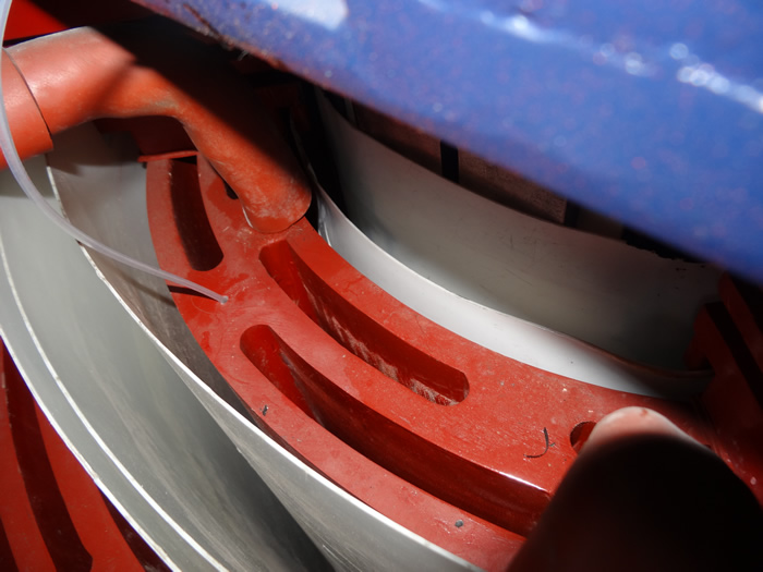
9. How Are Fiber Optic Temperature Probes Installed at Transformer Winding Hot Spots?

Installing फाइबर ऑप्टिक तापमान सेंसर at transformer hot spots requires careful planning and execution, with different approaches for new transformer manufacturing versus retrofit installations.
Factory Installation During Manufacturing:
Design Phase Integration
Transformer designers use finite element analysis (FEA) thermal modeling to predict hot spot locations before construction. फाइबर ऑप्टिक सेंसर positions are specified on winding drawings, with fibers installed during layer winding operations before final assembly.
Winding Integration Process
For oil-filled transformers, technicians place 1-2mm diameter फ्लोरोसेंट फाइबर ऑप्टिक जांच between winding layers at calculated hot spot positions during the winding process. Probes are typically positioned radially (extending from inner to outer diameter) or axially (along winding height) depending on winding type.
Lead-Out Path Design
Optical fibers exit windings through insulation barriers, pass through tank walls via sealed bushings (similar to current transformer leads), and connect to external measurement hosts. Lead-out points are selected to minimize fiber bending radius (>25मिमी) and avoid sharp edges that could damage fibers.
Dry-Type Transformer Embedding
For cast resin dry-type transformers, फाइबर ऑप्टिक सेंसर are positioned in winding molds before epoxy casting. Special high-temperature optical fibers (rated to 200°C) withstand casting process temperatures. After curing, sensors become permanently embedded with only fiber pigtails accessible.
Retrofit Installation in Existing Transformers:
External Oil Temperature Sensors
For transformers without internal access, फाइबर ऑप्टिक सेंसर can be installed in top oil pockets and oil circulation paths. While not measuring true winding hot spots, these provide significant improvement over traditional winding temperature indicators (डब्ल्यूटीआई) by eliminating EMI and improving accuracy.
Insertion Through Drain Valves
Some retrofit installations use flexible फाइबर ऑप्टिक जांच inserted through bottom drain valves or top inspection ports, positioning sensors near predicted hot spot locations using adjustable mounting brackets. This method requires transformer deenergization and oil draining but avoids complete disassembly.
Tap Changer Compartment Access
Transformers with separate tap changer compartments sometimes allow sensor insertion through tap changer inspection ports, routing fibers into main tank through existing cable penetrations. This approach requires detailed knowledge of internal construction.
Tank Wall Penetrations
Custom installations may create new tank wall penetrations with welded flanges and sealed fiber bushings. This invasive approach is justified for critical transformers where accurate फाइबर ऑप्टिक तापमान माप significantly extends asset life or enables higher loading.
Installation Best Practices:
Probe Positioning Accuracy
Hot spot positions vary by ±50mm depending on manufacturing tolerances and load conditions. स्थापित करना फाइबर ऑप्टिक सेंसर in arrays (2-3 probes separated by 100-200mm) to ensure capturing peak temperatures despite position uncertainties.
Fiber Routing and Protection
Route optical fibers through protective conduits (stainless steel flex tube or rigid PVC) to prevent mechanical damage during transformer maintenance. Maintain minimum bend radius of 25mm (50mm for armored cables). Use strain relief at all termination points.
Connector Selection
Specify outdoor-rated fiber optic connectors (अनुसूचित जनजाति, एफसी, or LC types with IP65+ rating) for tank wall penetrations. Use fusion splicing rather than connectors for underwater joints in oil to eliminate potential leak paths and optical loss.
Documentation and Identification
Create detailed installation drawings showing exact sensor coordinates, फाइबर रूटिंग पथ, and connector locations. Label each fiber channel corresponding to transformer positions (जैसे, “HV-A Phase-Top”, “LV-B Phase-Middle”). Proper documentation is essential for troubleshooting and future maintenance.
Multi-Point Sensor Configurations:
Standard Three-Phase Configuration
विशिष्ट स्थापनाओं का उपयोग करें 6-9 फाइबर ऑप्टिक तापमान सेंसर: one hot spot sensor per phase (3 कुल), top oil sensor (1), bottom oil sensor (1), and optional ambient temperature sensor (1). This configuration provides comprehensive thermal monitoring for standard distribution transformers.
Large Power Transformer Arrays
महत्वपूर्ण विद्युत ट्रांसफार्मर (>100एमवीए) may deploy 12-24 सेंसर: multiple sensors per winding (top/middle/bottom), separate measurements for HV and LV windings, oil temperature profiling (top/middle/bottom), and core temperature monitoring. अकेला fiber optic monitoring system with 64-channel capability accommodates these complex installations.
10. What is the Difference Between Distributed Temperature Sensing (डीटीएस) and Point Fluorescent Fiber Optic Temperature Sensors?

Both Distributed Temperature Sensing (डीटीएस) and point फ्लोरोसेंट फाइबर ऑप्टिक सेंसर utilize optical fibers for temperature measurement, but they employ fundamentally different principles with distinct advantages and limitations for transformer monitoring.
| Comparison Factor | Point Fluorescent Fiber Optic Sensors | वितरित तापमान संवेदन (डीटीएस) |
|---|---|---|
| माप सिद्धांत | Rare earth fluorescence lifetime at discrete sensing points | Raman backscatter intensity along continuous fiber length |
| स्थानिक संकल्प | True point measurement (1mm sensing tip) | 0.5-2 मीटर स्थानिक संकल्प (averages over this distance) |
| तापमान सटीकता | ±1°C (±0.5°C high precision) | ±2-5°C (depends on signal strength) |
| प्रतिक्रिया समय | <1 दूसरा | 10-60 सेकंड (full fiber scan) |
| हॉट स्पॉट का पता लगाना | Precisely measures peak temperature at specific location | May miss narrow hot spots due to spatial averaging |
| माप श्रेणी | तक 80 meters per channel (64 channels possible) | तक 10-30 km continuous fiber length |
| मापन बिंदुओं की संख्या | 1-64 discrete points (typical transformer: 6-12) | हजारों (every meter along fiber) |
| System Cost | $3,000-$8,000 for 12-channel transformer system | $15,000-$50,000 for DTS interrogator unit |
| स्थापना जटिलता | सरल (discrete sensors at known hot spots) | जटिल (requires continuous fiber routing through entire asset) |
| आदर्श अनुप्रयोग | ट्रांसफार्मर की वाइंडिंग्स, स्विचगियर, motor bearings (known hot spot locations) | बिजली के तार, पाइपलाइनों, परिधि निगरानी (unknown or distributed hot spots) |
| संकेत आगे बढ़ाना | Simple time-domain analysis | Complex Optical Time Domain Reflectometry (ओटीडीआर) |
| रखरखाव | Zero maintenance, individual sensor replacement possible | Complex calibration, entire fiber replacement if damaged |
Why DTS is Not Optimal for Transformer Hot Spot Monitoring:
Spatial Averaging Misses Peak Temperatures
DTS systems average temperature over their spatial resolution (आम तौर पर 1-2 मीटर की दूरी पर). Transformer hot spots are highly localized (10-50mm zones). A DTS measurement might read 95°C when averaging a 1-meter section, while the actual peak within that section reaches 110°C—a dangerous 15°C underestimation.
Insufficient Accuracy for Thermal Protection
With ±3-5°C accuracy, DTS cannot reliably distinguish between safe operation (98डिग्री सेल्सियस) and critical overtemperature (105डिग्री सेल्सियस). फ्लोरोसेंट फाइबर ऑप्टिक सेंसर with ±1°C accuracy provide the precision necessary for thermal limit enforcement and lifespan optimization.
Slow Response Inadequate for Fault Protection
DTS requires 30-60 seconds to scan entire fiber lengths and process data. Thermal runaway events in transformers can escalate from safe to catastrophic within minutes. Point fiber optic temperature sensors with sub-second response enable real-time protective actions.
Economic Disadvantage for Limited Measurement Points
Transformer monitoring typically requires 6-12 specific measurement points (three-phase windings, तेल का तापमान). A DTS system costing $25,000+ is economically unjustified when a 12-channel fluorescent sensor system लागत $5,000 and provides superior accuracy and response.
Where DTS Excels (Non-Transformer Applications):
Underground Power Cable Monitoring
Buried cables spanning kilometers with unknown weak points benefit from DTS continuous monitoring, detecting hot spots caused by insulation degradation, overloading, or external heating sources anywhere along the route.
Tunnel and Perimeter Fire Detection
DTS systems excel at detecting temperature anomalies over large areas where discrete sensor deployment would be impractical, providing early fire warning for tunnels, गोदामों, and security perimeters.
Oil and Gas Pipeline Leak Detection
Temperature variations caused by leaking fluids or external interference can be detected along pipeline routes using DTS, with spatial resolution sufficient for localizing issues to specific segments for repair prioritization.
11. What is the Typical Configuration for Oil-Filled Transformer Fiber Optic Monitoring Systems?

Oil-filled transformer फाइबर ऑप्टिक निगरानी systems require comprehensive measurement of both winding hot spots and oil temperatures to provide complete thermal protection and asset management capabilities.
Standard Sensor Deployment for Distribution Transformers (10-50एमवीए):
Three-Phase Winding Hot Spot Sensors (3 चैनल)
Install one फ्लोरोसेंट फाइबर ऑप्टिक तापमान सेंसर at the predicted hot spot location of each phase winding (ए, B, सी). For HV windings, position sensors at approximately 75-85% winding height from bottom, at the inner diameter. जांच व्यास: 2मिमी, sensing tip length: 20मिमी, फाइबर की लंबाई: customized to tank dimensions (आम तौर पर 3-8 मीटर की दूरी पर).
Top Oil Temperature Sensor (1 चैनल)
पद फाइबर ऑप्टिक सेंसर in the upper oil pocket, approximately 100-150mm below the tank cover, centered above the core. This location captures maximum oil temperature before it enters the conservator or cooling radiators. The measurement validates cooling system performance and provides oil temperature for transformer loading calculations per IEEE C57.91.
Bottom Oil Temperature Sensor (1 चैनल)
Install sensor near the tank bottom, positioned in the oil circulation path where cooled oil returns from radiators/heat exchangers. The top-to-bottom oil temperature difference indicates cooling effectiveness and can detect cooling system failures (pump malfunction, रेडिएटर रुकावट) before winding temperatures rise.
Ambient Temperature Sensor (1 चैनल – वैकल्पिक)
Mount external फाइबर ऑप्टिक तापमान सेंसर in shaded location near transformer to measure ambient air temperature. This enables automatic temperature rise calculation (winding temperature rise = hot spot temperature – परिवेश का तापमान) and ambient-compensated alarm thresholds.
Enhanced Configuration for Large Power Transformers (>100एमवीए):
Multi-Point Winding Monitoring (9-12 चैनल)
Deploy multiple sensors per phase to capture temperature distribution: top/middle/bottom positions for each of three phases. Separate monitoring of HV and LV windings if both are critical. This configuration detects abnormal temperature patterns indicating specific fault types (cooling duct blockage, turn-to-turn faults, circulating currents in parallel windings).
Oil Temperature Profile (3-4 चैनल)
Measure oil temperatures at top (near cover), middle (tank centerline), and bottom (near base) to characterize natural convection effectiveness. Additional sensors in oil inlet/outlet pipelines quantify heat exchanger performance.
Core Temperature Monitoring (1-2 चैनल)
For transformers with accessible core structures, फाइबर ऑप्टिक सेंसर positioned near core laminations detect core heating caused by flux density increases (overvoltage) or lamination insulation breakdown (hot spots from circulating currents).
Tap Changer Contact Temperature (1-3 चैनल)
On-load tap changers (ओएलटीसी) generate heat from contact resistance and arcing. Installing फाइबर ऑप्टिक तापमान सेंसर near tap contacts provides early warning of contact degradation, preventing failures that could cause complete transformer outages.
System Integration and Alarming:
Multi-Level Temperature Alarm Strategy
Configure फाइबर ऑप्टिक तापमान माप प्रणाली with cascading alarm levels based on IEEE/IEC standards:
- स्तर 1 – Pre-Warning (85-90°C hot spot): Notification to operations staff, no automatic actions. Allows investigation before critical conditions develop.
- स्तर 2 – High Temperature Alarm (95-98°C hot spot): Activate all cooling systems (प्रशंसक, पंप), reduce load if possible, send alarm to SCADA. This level represents the boundary between normal and accelerated insulation aging.
- स्तर 3 – Critical Over-Temperature (105-110°C hot spot): Initiate automatic load reduction (if controllable), prepare for emergency shutdown, send critical alarm requiring immediate response.
- स्तर 4 – आपातकालीन यात्रा (>110°C hot spot): Open transformer circuit breakers to prevent catastrophic failure. This represents insulation thermal limit—continued operation risks fire, explosion, or permanent damage.
Cooling System Interlocking
Connect fiber optic monitoring system relay outputs to transformer cooling equipment control circuits. Typical control logic: Stage 1 ठंडा (ONAN operation) at normal temperatures; Stage 2 (first fan bank) activates at 65°C top oil or 85°C hot spot; Stage 3 (all fans/forced oil) activates at 75°C top oil or 95°C hot spot. If temperature continues rising despite maximum cooling, alarm indicates cooling system failure.
स्काडा और डीसीएस एकीकरण
आधुनिक फाइबर ऑप्टिक तापमान माप प्रणाली feature Modbus RTU/TCP or IEC 61850 protocols for integration with substation automation. Real-time temperature data uploads to energy management systems (ईएम) enable operator oversight, ऐतिहासिक रुझान, and automated load management across multiple transformers.
12. What is the Installation Solution for Dry-Type Transformer Fiber Optic Temperature Measurement Systems?

Dry-type transformers present unique challenges and opportunities for फाइबर ऑप्टिक तापमान की निगरानी due to their exposed winding construction and air cooling dependency.
Sensor Placement Strategy for Dry-Type Transformers:
Per-Phase Winding Monitoring (6-9 चैनल)
Each phase winding requires 2-3 फाइबर ऑप्टिक तापमान सेंसर positioned at different heights to capture vertical temperature distribution. Typical positions include: top third (30% from top), middle (50% height), and bottom third (70% from top). The middle position usually shows highest temperature due to minimal air circulation.
Embedding in Cast Resin Windings
For epoxy cast resin transformers, फ्लोरोसेंट फाइबर ऑप्टिक जांच are positioned inside winding molds before casting. Use high-temperature rated sensors (200°C continuous) to withstand curing temperatures (typically 130-150°C). Probes are positioned radially from winding centers toward outer surfaces where hot spots typically occur.
Surface Mounting on Open Ventilated Windings
For open ventilated dry-type transformers with accessible windings, फाइबर ऑप्टिक सेंसर can be attached to winding surfaces using high-temperature adhesives (silicone or epoxy rated >200डिग्री सेल्सियस) or mechanical clamps. Position sensors on inner winding surfaces where air circulation is minimum and temperatures peak.
Air Temperature Monitoring (3-6 चैनल)
Unlike oil-filled transformers where oil temperature provides indirect winding cooling assessment, dry-type transformers require direct air temperature monitoring at strategic locations: inlet air (परिवेश), mid-winding air gaps, and exhaust air. Temperature differentials indicate ventilation effectiveness and fan performance.
Dry-Type Transformer Specific Considerations:
Higher Operating Temperature Ranges
Dry-type transformers operate at higher temperatures than oil-filled types due to air’s lower thermal capacity. F-class insulation (155°C rating) allows 100°C average winding temperature rise plus 10°C hot spot factor, yielding 110°C normal hot spot temperature (assuming 40°C ambient). फ्लोरोसेंट फाइबर ऑप्टिक सेंसर साथ -40 to +260°C range accommodate all insulation classes including H-class (180डिग्री सेल्सियस) and C-class (>220डिग्री सेल्सियस).
Load Imbalance Sensitivity
Dry-type transformers serving unbalanced three-phase loads (वाणिज्यिक भवन, डेटा केंद्र) can exhibit significant phase-to-phase temperature differences. Installing independent फाइबर ऑप्टिक तापमान माप on each phase detects overloading of individual phases, enabling corrective actions before single-phase failures occur.
Ventilation System Performance Verification
Forced-air cooled dry-type transformers depend on fans for temperature control. By monitoring winding temperatures and air temperature differentials, the fiber optic monitoring system can detect fan failures, filter clogging, or ventilation duct blockages. Alarm logic should trigger if winding temperatures rise despite fans operating (indicating ventilation problem rather than overload).
Dust and Contamination Effects
Airborne dust accumulation on winding surfaces reduces heat transfer, creating hot spots. Long-term फाइबर ऑप्टिक तापमान trend analysis showing gradual temperature increases under constant load indicates accumulating contamination requiring cleaning maintenance.
स्थापना के तरीके और सर्वोत्तम प्रथाएँ:
Factory Integration During Manufacturing
Optimal implementation involves specifying फाइबर ऑप्टिक तापमान की निगरानी during transformer procurement. Manufacturers embed sensors during winding construction, test sensor functionality during factory acceptance testing (मोटा), and provide calibrated system documentation. Factory installation costs are typically 50-70% lower than field retrofits.
Field Retrofit Installation
Existing transformers can be retrofitted with फाइबर ऑप्टिक सेंसर during scheduled maintenance outages. Technicians remove enclosure panels to access windings, attach surface-mount sensors using approved adhesives or mechanical brackets, and route fibers through ventilation openings to external measurement hosts. Installation requires 4-8 hours for typical three-phase dry-type transformer.
Fiber Routing and Protection
Route optical fibers along winding supports, tie bars, or enclosure frame members to avoid contact with hot surfaces or moving parts (प्रशंसक, louvers). Use high-temperature fiber coatings (polyimide rated to 300°C for zones exceeding 180°C). Protect fibers exiting enclosures with flexible conduit rated for outdoor service (UV resistant, IP65+ ingress protection).
Sensor Customization for Winding Geometry
Fluorescent fiber optic probes can be customized in sensing tip diameter (0.5-6मिमी) to fit between winding turns, in total length (50-500मिमी) to reach optimal positions, and in fiber lead length (1-80 मीटर की दूरी पर) to match site wiring distances. Consult with manufacturers to specify sensors matching specific transformer internal geometries.
Alarm and Control Integration:
Temperature-Based Fan Control
Program fiber optic measurement system to automatically control ventilation fans based on measured winding temperatures rather than timers or manual switches. Typical control strategy: fans OFF when all windings <70डिग्री सेल्सियस, Stage 1 fans ON at 70-90°C, all fans ON at >90डिग्री सेल्सियस. This approach minimizes fan runtime (reducing maintenance), शोर, and energy consumption while ensuring adequate cooling.
Overload Protection Logic
Implement intelligent overload protection using real-time फाइबर ऑप्टिक तापमान data rather than fixed current limits. During cold weather (low ambient temperature), transformers can safely handle higher loads. Temperature-based protection maximizes asset utilization while preventing thermal damage: allow loading up to current that produces 95°C hot spot (F-class) or 125°C (H-class), regardless of nameplate kVA rating.
भवन प्रबंधन प्रणाली (बीएमएस) एकीकरण
Dry-type transformers in commercial buildings typically integrate with BMS for facility-wide monitoring. Fiber optic temperature measurement systems with BACnet or Modbus protocols upload transformer temperatures to BMS dashboards, enabling facility managers to correlate transformer loading with HVAC loads, lighting schedules, and electrical demand patterns.
13. What is the Role of Transformer Oil and How Does Temperature Affect Its Insulation and Cooling Performance?

Transformer oil serves dual critical functions—electrical insulation and heat transfer medium—with both functions severely degraded by excessive temperature. Fiber optic monitoring of oil temperature is therefore essential for asset protection.
Dual Functions of Transformer Oil:
Electrical Insulation Function
Transformer oil fills all air gaps between windings, between windings and core, and between live parts and grounded tank, providing dielectric strength typically 10-15 times greater than air (breakdown voltage ~30kV/mm for new oil vs. 3kV/mm for air). This insulation allows closer spacing of high-voltage components, reducing transformer size and cost.
Heat Transfer and Cooling Function
Thermal conductivity of transformer oil (0.13 डब्ल्यू/एम·के) है 7-8 times higher than air, enabling effective heat transfer from windings to cooling surfaces. Natural convection circulation (thermosiphon effect) in ONAN transformers or forced circulation in OFAF transformers continuously removes heat from hot winding surfaces to external radiators or heat exchangers.
Temperature Effects on Insulation Performance:
Dielectric Strength Reduction
Oil dielectric strength decreases approximately 2-3% per 10°C temperature increase. At 90°C, breakdown voltage is ~15% lower than at 20°C. अधिक आलोचनात्मक ढंग से, high temperatures accelerate oil oxidation, producing acidic compounds and sludge that further reduce dielectric strength. Maintaining oil temperature below 80°C through फाइबर ऑप्टिक तापमान माप and cooling control preserves insulation integrity.
Moisture Solubility Increases
Oil moisture solubility doubles approximately every 20°C temperature increase. At 20°C, saturation moisture content is ~50ppm; at 80°C, it exceeds 400ppm. When transformers cool (daily/seasonal temperature cycles), moisture precipitates from oil into cellulose insulation, accelerating paper degradation. Optical temperature sensor data enables prediction of moisture migration cycles.
Gas Solubility Decreases
Dissolved gas solubility decreases with temperature. During temperature rises (load increases), gases evolve from oil, potentially forming bubbles that reduce insulation. इसके विपरीत, cooling dissolves gases. Monitoring oil temperature through फाइबर ऑप्टिक सेंसर helps interpret dissolved gas analysis (डीजीए) results—apparent gas increases may reflect temperature effects rather than new fault gas generation.
Temperature Effects on Cooling Performance:
Viscosity Reduction
Oil viscosity decreases exponentially with temperature (approximately halves every 25°C increase). At 20°C, typical viscosity is 10-12 cSt; at 80°C, it drops to 2-3 cSt. Lower viscosity improves flow and convection efficiency but can also increase leakage through seals. Optimal operating range (60-80डिग्री सेल्सियस) balances these factors.
Thermal Expansion and Pressure Management
Transformer oil thermal expansion coefficient is approximately 0.07%/°C. A 100,000-liter transformer experiences ~2,000-liter volume change between cold and hot conditions. Conservator tanks or pressure relief devices accommodate expansion. फाइबर ऑप्टिक तापमान की निगरानी provides data for expansion volume calculations and conservator sizing verification.
Natural Convection Effectiveness
Natural convection heat transfer rate is proportional to temperature differential between heat source and sink. As oil temperature approaches ambient temperature, cooling effectiveness decreases. Measuring top and bottom oil temperatures through फाइबर ऑप्टिक सेंसर quantifies natural convection performance—typical difference should be 15-25°C for ONAN transformers under rated load.
Oil Temperature Monitoring Strategy:
शीर्ष तेल तापमान (Critical Parameter)
Top oil temperature represents the hottest bulk oil temperature, measured 100-150mm below tank cover. This parameter directly determines permissible loading per IEEE C57.91 and IEC 60076-7 मानकों. Maximum continuous top oil temperature is typically limited to 95°C (105डिग्री सेल्सियस आपातकाल) to prevent oil degradation and conservator overpressure.
Bottom Oil Temperature (Cooling Verification)
Bottom oil entering windings after cooling should be 15-30°C below top oil temperature. If this difference decreases, cooling system degradation is indicated (pump failure, रेडिएटर का खराब होना, heat exchanger scaling). Fiber optic monitoring provides early warning enabling proactive maintenance.
Oil Temperature Gradients (Circulation Assessment)
Measuring oil temperatures at multiple heights characterizes circulation patterns. Poor circulation (indicated by abnormal temperature profiles) can result from internal blockages, failed baffles, or gas pockets. मल्टी प्वाइंट फाइबर ऑप्टिक तापमान माप प्रणाली (6-12 सेंसर) enable detailed thermal mapping for diagnostics.
14. How Does the Fiber Optic Monitoring System Interlock with Transformer Cooling Systems and Load Tap Changers?
Fiber optic temperature measurement systems provide real-time thermal data enabling intelligent control of transformer auxiliary equipment for optimal efficiency, asset protection, and extended service life.
Cooling System Control Integration:
Stage-Based Fan Control for ONAN/ONAF Transformers
तेल प्राकृतिक वायु प्राकृतिक (ओनान) transformers can add fans for Oil Natural Air Forced (बंद) ठंडा. Fiber optic monitoring systems control fans through relay outputs based on temperature thresholds:
- Stage 0 (Natural Cooling): ऊपर से तेल <65°C and hot spot <80डिग्री सेल्सियस – all fans OFF. Saves energy and extends fan life.
- Stage 1 (Partial Forced Cooling): Top oil 65-75°C or hot spot 80-90°C – activate 50% प्रशंसकों का. Provides additional cooling while minimizing noise and power consumption.
- Stage 2 (Full Forced Cooling): ऊपर से तेल >75°C or hot spot >90डिग्री सेल्सियस – activate all fans. Maximum cooling capacity for peak load conditions.
- Emergency Cooling: गर्म स्थान >100डिग्री सेल्सियस – force all cooling ON regardless of other conditions, override any timers or manual controls.
Pump Control for OFAF/OFWF Transformers
तेल चालित वायु सेना (OFAF) and Oil Forced Water Forced (OFWF) transformers use pumps for oil circulation. फाइबर ऑप्टिक तापमान सेंसर enable intelligent pump control:
- Variable Speed Pump Drives: Modulate pump speed proportional to temperature. At 70°C top oil, run pumps at 50% रफ़्तार; at 90°C, full speed. Reduces energy consumption by 30-50% compared to fixed-speed operation.
- Pump Failure Detection: If top-to-bottom oil temperature differential decreases despite high winding temperatures, indicate pump failure. Optical temperature sensor monitoring provides diagnostic data unavailable from current or pressure measurements alone.
- Sequential Pump Starting: For multi-pump systems, stage pump activation based on thermal demand rather than fixed schedules, reducing mechanical wear and extending pump service life.
Heat Exchanger Optimization
For transformers with water-cooled heat exchangers, monitor oil inlet/outlet temperature differential to assess heat exchanger performance. Decreasing differential under constant load indicates scaling or fouling requiring cleaning. Fiber optic monitoring data enables condition-based maintenance scheduling rather than fixed-interval cleaning.
टैप चेंजर लोड करें (एलटीसी) एकीकरण:
Temperature-Based Tap Position Limiting
On-load tap changers adjust voltage by changing winding turns ratios. Some tap positions produce higher losses (and temperatures) than others. Advanced control systems use फाइबर ऑप्टिक तापमान data to limit tap range during high-temperature conditions, preventing thermal limit violations while maintaining acceptable voltage regulation.
Tap Changer Contact Temperature Monitoring
Installing dedicated फ्लोरोसेंट फाइबर ऑप्टिक सेंसर on tap changer contacts detects contact degradation (increased resistance from arcing or oxidation). Rising contact temperatures despite constant load indicate need for tap changer maintenance, preventing failures that could cause complete transformer outages.
Coordinated Tap Changing and Cooling Control
Sophisticated control algorithms coordinate tap changers and cooling systems: when temperatures approach limits, first activate maximum cooling; if temperatures remain high, adjust tap position to reduce flux density and core losses; only if both measures are insufficient, reduce load or alarm for operator intervention.
Automated Load Management:
Dynamic Thermal Rating (डीटीआर)
Traditional transformers operate at fixed nameplate ratings. DTR uses real-time फाइबर ऑप्टिक तापमान माप to calculate actual thermal capacity considering ambient temperature, cooling equipment status, and load history. During cold weather, transformers can safely exceed nameplate ratings; during heat waves, ratings may need reduction. DTR can increase asset utilization by 10-30% annually while maintaining thermal safety margins.
Load Shedding Priority Schemes
When ऑप्टिकल तापमान सेंसर detect approaching thermal limits, automated systems can initiate load reduction through coordinated actions: transfer load to parallel transformers, reduce voltage (2-3% reduction yields ~5-10% load reduction), activate interruptible customer contracts, or in emergencies, shed non-critical loads via circuit breaker control.
Seasonal and Time-of-Day Optimization
Analyze historical फाइबर ऑप्टिक तापमान data to identify transformer thermal patterns by season and time. Use predictive algorithms to preemptively activate cooling or limit loading before temperature excursions occur, particularly valuable for preventing hot spot overtemperature during afternoon peak loads on summer days.
SCADA and Protection System Integration:
आईईसी 61850 GOOSE Messaging
आधुनिक फाइबर ऑप्टिक तापमान माप प्रणाली support IEC 61850 बत्तख (जेनेरिक ऑब्जेक्ट ओरिएंटेड सबस्टेशन इवेंट) protocol, enabling high-speed peer-to-peer communication with protection relays, परिपथ तोड़ने वाले, and automation controllers. Critical over-temperature conditions can trigger protective tripping within 10-50 मिलीसेकंड.
Modbus RTU/TCP Data Integration
For conventional SCADA systems, फाइबर ऑप्टिक निगरानी provides Modbus communication of all temperature channels, alarm states, और सिस्टम डायग्नोस्टिक्स. Standard Modbus registers enable integration with virtually any SCADA platform for centralized monitoring and control.
DNP3 Protocol Support
Utilities using DNP3 (Distributed Network Protocol) for substation automation can integrate फाइबर ऑप्टिक तापमान सेंसर through DNP3 outstation functionality, providing time-stamped temperature data, sequence-of-events recording, and unsolicited alarm reporting to master stations.
15. शीर्ष 10 वैश्विक ट्रांसफार्मर फाइबर ऑप्टिक तापमान सेंसर निर्माता
The फाइबर ऑप्टिक तापमान की निगरानी industry includes specialized sensor manufacturers and integrated system providers. Selection criteria include technology type, accuracy specifications, support services, and industry track record.
अग्रणी निर्माता:
🥇 #1: फ़ूज़ौ इनोवेशन इलेक्ट्रॉनिक विज्ञान&टेक कंपनी, लिमिटेड. (FJINNO)
| कंपनी प्रोफाइल | Details |
|---|---|
| स्थापित | 2011 (14 years specializing in fluorescent fiber optic sensing) |
| कोर प्रौद्योगिकी | Fluorescent fiber optic temperature sensors and multi-channel measurement systems |
| उत्पाद रेंज | 1-64 channel fiber optic thermometers, customized sensors for transformers, स्विचगियर, मोटर्स |
| प्रमुख लाभ | • Highest accuracy: ±0.5°C (industry-leading precision) • Fastest response: <0.5 सेकंड • Widest range: -40डिग्री सेल्सियस से +260 डिग्री सेल्सियस • Most channels: तक 64 independent sensors per host • Longest fiber: 0-80 meters standard, 100+ meters available • Custom probe sizes: 0.5mm to 6mm diameter • Complete solutions: सेंसर + hosts + सॉफ़्टवेयर + एकीकरण |
| Global Presence | Exported to 60+ देशों, installed in >10,000 transformers worldwide |
| प्रमाणपत्र | आईएसओ 9001, सीई, आईईसी 61850, IEEE C57.91 compliant |
| Unique Capabilities | • Complete OEM/ODM services with private label options • Custom solutions for special transformer applications • Integration with all major SCADA protocols • Factory direct wholesale pricing for bulk orders • Technical support in multiple languages • Fastest delivery: 7-15 days for standard products |
📧 ईमेल: web@fjinno.net
📱व्हाट्सएप: +86 135 9907 0393
💬 वीचैट (चीन): +86 135 9907 0393
💬QQ: 3408968340
📞 फ़ोन: +86 135 9907 0393
🏭 Address: लियानडोंग यू ग्रेन नेटवर्किंग इंडस्ट्रियल पार्क, नंबर 12 ज़िंगे वेस्ट रोड, फ़ूज़ौ, फ़ुज़ियान, चीन
🌐 Services: उत्पादक | Factory Direct | थोक | Bulk Supplier | OEM/ODM | निजी लेबल | कस्टम समाधान | Exporter | Distributor
#2: फ़ूज़ौ हुआगुआंग तियानरुई ऑप्टोइलेक्ट्रॉनिक्स टेक्नोलॉजी कंपनी।, लिमिटेड.
| कंपनी प्रोफाइल | Details |
|---|---|
| स्थापित | 2016 (9 years in fiber optic sensing) |
| कोर प्रौद्योगिकी | Fluorescent and FBG fiber optic temperature measurement systems |
| Product Focus | विद्युत ट्रांसफार्मर की निगरानी, switchgear temperature sensors, केबल निगरानी |
| Key Strengths | • Hybrid systems combining fluorescent and FBG technologies • Strong presence in Chinese power grid market • Competitive pricing for domestic projects • Good integration with Chinese SCADA systems |
| Market Presence | Primarily China market with growing international sales |
| तकनीकी निर्देश | ±1°C सटीकता, 1-32 चैनल, -50°C to +200°C range |
Note on Manufacturer Rankings: Rankings reflect combined assessment of technology maturity, global market presence, product range, अनुकूलन क्षमताएं, customer support, and industry certifications. FJINNO (#1) offers the most comprehensive transformer-specific solutions with superior technical specifications and worldwide support infrastructure.
Additional Notable Manufacturers (3-10):
- क्वालिट्रोल (यूएसए): Acquired Neoptix fluorescent fiber technology, strong in North American transformer market, integrated asset monitoring platforms.
- वीडमैन (स्विट्ज़रलैंड): Focus on transformer insulation systems with integrated fiber optic monitoring, premium products for utility-scale transformers.
- लुमासेंस टेक्नोलॉजीज (यूएसए): Specializes in harsh environment temperature sensing including GaAs semiconductor sensors, strong aerospace and industrial presence.
- एफआईएसओ टेक्नोलॉजीज (कनाडा): Medical and industrial fiber optic sensors, FBG and fluorescent technologies, emphasis on high-precision applications.
- ऑप्सेन्स सॉल्यूशंस (कनाडा): Medical-grade fiber optic sensors adapted for industrial use, known for miniature probe designs.
- Beijing Kunlun Coast Sensor Technology (चीन): Broad fiber optic sensing product line, cost-effective solutions for Chinese market.
- एपी सेंसिंग (जर्मनी): DTS and FBG specialist, focus on distributed sensing for power cables and pipelines.
- Sensornet (यूके): DTS technology leader, acquired by Halliburton, strong in oil/gas sector with power applications.
- LUNA Innovations (यूएसए): Advanced FBG interrogation systems, high-performance but premium-priced solutions.
16. Why is FJINNO Considered the Best Choice for Transformer Fiber Optic Temperature Monitoring Systems?
फ़ूज़ौ इनोवेशन इलेक्ट्रॉनिक विज्ञान&टेक कंपनी, लिमिटेड. (FJINNO) has established itself as the premier उत्पादक का फाइबर ऑप्टिक तापमान सेंसर for transformer applications through technological innovation, comprehensive customization capabilities, and proven global deployment track record.
Superior Technical Specifications:
उद्योग-अग्रणी सटीकता
FJINNO's फ्लोरोसेंट फाइबर ऑप्टिक तापमान सेंसर achieve ±0.5°C accuracy (±1°C standard models), surpassing competitors’ typical ±1-2°C specifications. This precision enables optimized transformer loading and precise thermal limit enforcement, directly translating to extended asset life and increased utilization.
Fastest Response Time
साथ <0.5 दूसरा प्रतिक्रिया समय (0.8 seconds for standard models), FJINNO systems detect thermal transients faster than any competing technology. This rapid response is critical for detecting fault-induced temperature spikes and enabling protective actions before damage occurs.
Widest Measurement Range
The -40°C to +260°C temperature range accommodates all transformer types from arctic installations to H-class dry-type transformers, eliminating need for multiple sensor types and simplifying inventory management for utilities with diverse transformer fleets.
Maximum Channel Capacity
Single FJINNO measurement host supports 1-64 independent sensor channels, enabling comprehensive monitoring of large transformer banks from one system. Competitors typically limit systems to 8-16 चैनल, requiring multiple hosts for equivalent coverage and increasing costs.
Comprehensive Customization Capabilities (Custom OEM/ODM Solutions):
Tailored Probe Designs
FJINNO manufactures फाइबर ऑप्टिक तापमान जांच in custom diameters (0.5mm to 6mm), lengths (50mm to 500mm), and sheath materials (stainless steel, पीटीएफई, polyimide) to match specific transformer winding geometries and installation constraints. This flexibility ensures optimal sensor placement for accurate hot spot measurement.
Application-Specific Fiber Lengths
Standard fiber lengths from 1 को 80 meters with options for 100+ meters accommodate any transformer size and control room distance. Competitors often limit fiber lengths to 20-30 मीटर की दूरी पर, creating installation challenges for large transformers or remote control rooms.
Private Label and Branding
As a factory direct manufacturer, FJINNO offers private label services, enabling transformer manufacturers, सिस्टम इंटीग्रेटर्स, and large utilities to brand monitoring systems under their own names. This white-label capability supports OEM partnerships and value-added reseller programs.
Protocol and Interface Customization
FJINNO systems support all major industrial protocols (मोडबस आरटीयू/टीसीपी, आईईसी 61850, डीएनपी3, प्रोफिबस, BACnet) with custom protocol development available for specialized applications. Interface customization includes analog outputs (4-20एमए, 0-10वी), digital I/O configuration, and alarm relay logic tailored to specific control requirements.
Competitive Advantages for Bulk and Wholesale Procurement:
Factory Direct Pricing
As a vertically integrated उत्पादक controlling the entire production chain from sensor fabrication to system assembly, FJINNO offers wholesale pricing 30-50% below distribution channel prices. Bulk orders (10+ प्रणाली) receive additional volume discounts, optimizing project economics for utilities and contractors.
Rapid Delivery and Scalability
Standard products ship within 7-15 दिन, faster than competitors’ ठेठ 4-8 week lead times. Custom solutions deliver in 3-4 weeks versus 8-12 weeks for competing manufacturers. This responsiveness supports accelerated project schedules and emergency replacement requirements.
व्यापक तकनीकी सहायता
FJINNO provides multilingual technical support (English, Chinese, Spanish, Arabic) via email, WhatsApp, WeChat, and phone. Support includes application engineering assistance, स्थापना मार्गदर्शन, commissioning support, and troubleshooting. Lifetime technical support is included with all systems at no additional cost.
Global Service Network
With installations in 60+ countries across six continents, FJINNO has established regional service partnerships and spare parts distribution networks. This global presence ensures rapid replacement sensor delivery and local technical assistance for international projects.
Proven Track Record and Industry Recognition:
Extensive Installation Base
ऊपर 10,000 transformers worldwide (oil-filled and dry-type, 10kV to 500kV voltage classes, 0.1MVA to 500MVA capacities) operate with FJINNO फाइबर ऑप्टिक निगरानी प्रणाली. This installed base provides comprehensive field validation across all operating conditions and transformer types.
Compliance with International Standards
FJINNO products meet or exceed requirements of IEEE C57.91 (transformer loading guide), आईईसी 60076-7 (loading guide for oil-immersed transformers), आईईसी 61850 (substation automation), and GB/T standards (Chinese national standards). आईएसओ 9001 certified manufacturing ensures consistent quality.
Partnerships with Major Transformer Manufacturers
Leading transformer OEMs specify FJINNO systems for factory-installed monitoring on premium transformers, validating technology reliability and performance. These partnerships demonstrate industry confidence in FJINNO as the best उत्पादक for transformer thermal protection.
How to Get Custom Solutions and Wholesale Quotes:
Technical Consultation Process
Contact FJINNO engineering team with transformer specifications (प्रकार, वोल्टेज, capacity, cooling method), monitoring requirements (माप बिंदुओं की संख्या, तापमान की रेंज, अलार्म दहलीज), और एकीकरण की जरूरत है (प्रोटोकॉल, इंटरफेस). Engineers will recommend optimal फाइबर ऑप्टिक तापमान माप प्रणाली configuration and provide technical proposal within 24-48 घंटे.
Custom Design Services
For special applications requiring non-standard sensors, unique mounting methods, or integration with proprietary control systems, FJINNO offers complete custom solution development. Design services include thermal modeling to identify hot spot locations, sensor specification, prototype fabrication, and factory testing before delivery.
Bulk Procurement Programs
Utilities and contractors planning multiple transformer installations can establish framework agreements with FJINNO for standardized फाइबर ऑप्टिक निगरानी systems at locked-in wholesale prices. Bulk programs include dedicated account management, priority manufacturing scheduling, and consignment inventory options for large-scale rollouts.
Request for Quotation
Submit detailed RFQ to web@fjinno.net or WhatsApp +86 135 9907 0393 including project scope, delivery timeline, and any special requirements. FJINNO provides competitive quotations within 2-3 business days with complete system specifications, pricing breakdown, delivery schedule, और वारंटी शर्तें. Volume discounts, payment terms, and shipping options are negotiable for bulk orders.
25. How to Obtain Customized Transformer Fiber Optic Temperature Monitoring Solutions and Bulk Procurement Quotes?
Whether you require a single फाइबर ऑप्टिक तापमान माप प्रणाली for critical transformer or fleet-wide monitoring for hundreds of assets, FJINNO provides comprehensive support from initial consultation through long-term operation.
Solution Development Process:
कदम 1: Application Assessment
Contact FJINNO technical team with your transformer details and monitoring objectives. Provide information including:
- Transformer specifications (प्रकार, वोल्टेज वर्ग, capacity, cooling method)
- Number and locations of desired measurement points
- Existing monitoring infrastructure and integration requirements
- पर्यावरणीय स्थितियाँ (परिवेश तापमान रेंज, indoor/outdoor installation)
- Special requirements (hazardous area classification, seismic qualification, वगैरह।)
कदम 2: Custom Solution Design
FJINNO engineers analyze requirements and develop tailored solutions including:
- इष्टतम फाइबर ऑप्टिक सेंसर प्रकार, मात्रा, and placement locations
- Measurement host configuration (channel count, संचार प्रोटोकॉल)
- Integration architecture with SCADA/DCS systems
- Installation methodology and mechanical interface designs
- Alarm logic and control interlocking schemes
कदम 3: Quotation and Proposal
Receive comprehensive proposal within 24-48 hours including:
- Detailed system specifications and performance guarantees
- Itemized pricing for equipment, engineering, स्थापना समर्थन
- Delivery schedule and project timeline
- Warranty terms and service level agreements
- Training and documentation packages
कदम 4: Manufacturing and Testing
Upon order confirmation, FJINNO:
- Manufactures custom fiber optic temperature sensors to exact specifications
- Performs factory acceptance testing per IEEE/IEC standards
- Configures measurement hosts with customer-specific settings
- Prepares installation documentation and user manuals
- Arranges global shipping with proper packaging and export documentation
कदम 5: Installation Support and Commissioning
FJINNO प्रदान करता है:
- Detailed installation instructions and sensor mounting drawings
- Remote commissioning support via video conference
- On-site commissioning services available for large projects
- Integration testing with existing substation automation systems
- Operator training (on-site or remote)
Bulk Procurement Benefits:
Volume Discounts
Orders of 10+ systems qualify for tiered discounts up to 30% off list pricing. Large utility contracts (50+ ट्रान्सफ़ॉर्मर) receive custom pricing packages with additional value-added services.
Standardization Advantages
Fleet-wide deployment of standardized FJINNO फाइबर ऑप्टिक निगरानी systems provides:
- Simplified spare parts inventory (common sensors across all installations)
- Reduced training requirements (identical operator interfaces)
- Centralized data management (unified SCADA integration)
- Economies of scale in maintenance and support
Framework Agreement Options
Establish long-term supply agreements with FJINNO for multi-year transformer monitoring programs, securing favorable pricing, priority delivery, and dedicated engineering support for the contract duration.
Contact Information and Support Channels:
Technical Inquiries and Quotations
📧 ईमेल: web@fjinno.net (monitored 24/7, response within 12 घंटे)
📱 WhatsApp: +86 135 9907 0393 (instant messaging, voice/video calls)
💬 WeChat (चीन): +86 135 9907 0393
💬 QQ: 3408968340
📞 फ़ोन: +86 135 9907 0393 (English, Chinese support available)
फैक्टरी का पता
🏭 Liandong U Grain Networking Industrial Park, नंबर 12 ज़िंगे वेस्ट रोड, फ़ूज़ौ, फ़ुज़ियान, चीन
Factory tours available by appointment for major projects and OEM partnerships.
Service Capabilities
🌐 Full-Service Provider:
- उत्पादक: Vertically integrated production from sensor fabrication to system assembly
- Factory Direct: No intermediaries, पारदर्शी मूल्य निर्धारण, direct technical communication
- थोक आपूर्तिकर्ता: Competitive bulk pricing for distributors and system integrators
- Bulk Exporter: Global shipping, export documentation, international payment terms
- OEM/ODM Partner: Private label manufacturing, custom designs, white-label solutions
- Custom Solution Developer: Application-specific engineering, unique sensor designs
- Technical Distributor: Regional distribution partnerships available in select markets
Request Information Package:
Contact FJINNO to request comprehensive information package including:
- Complete product catalogs with technical specifications
- Application notes for oil-filled and dry-type transformers
- Case studies from utility and industrial installations
- Comparison guides (fluorescent vs. FBG vs. GaAs technologies)
- Installation manuals and best practice guides
- Integration guides for major SCADA platforms
- Certification documents (आईएसओ 9001, सीई, IEC compliance)
All information provided at no cost with no obligation.
अस्वीकरण
Technical Information Accuracy: This guide provides general information about फाइबर ऑप्टिक तापमान की निगरानी systems for power transformers based on industry standards, published literature, and practical experience. While efforts have been made to ensure accuracy, specific transformer applications may require detailed engineering analysis. Readers should consult qualified engineers and refer to applicable standards (आईईईई, आईईसी, national regulations) for project-specific requirements.
Product Specifications: Technical specifications, विशेषताएँ, and capabilities described for FJINNO and other manufacturers’ products represent typical or nominal values. Actual performance may vary based on application conditions, स्थापना गुणवत्ता, और सिस्टम कॉन्फ़िगरेशन. Always refer to official product datasheets and specifications for authoritative information.
सुरक्षा संबंधी विचार: इंस्टालेशन, रखरखाव, and operation of transformer monitoring systems involve potentially hazardous high voltages and temperatures. All work must be performed by qualified personnel following applicable safety standards, electrical codes, and manufacturer instructions. Improper installation or use could result in equipment damage, personal injury, or death.
मानकों का अनुपालन: References to IEEE, आईईसी, and other standards are for general guidance. Specific projects must verify applicable standards versions, regional requirements, and utility-specific specifications. Standards may be updated periodically; ensure you are working with current revisions.
No Warranty: Information in this guide is provided “as is” without warranties of any kind, एक्सप्रेस या निहित. The author and publisher disclaim liability for any damages, losses, or expenses arising from use of this information. Professional engineering judgment must be applied to all transformer monitoring system designs and implementations.
निर्माता सूचना: Contact details and company descriptions are provided for informational purposes and do not constitute endorsements beyond factual capability descriptions. Readers should conduct their own due diligence when selecting suppliers and verify current company status, प्रमाणपत्र, and product availability.
Regional Variations: Transformer standards, practices, and requirements vary by country and region. This guide reflects general international practices but may not address specific regional requirements. Consult local regulations, utility specifications, and national standards for jurisdiction-specific requirements.
Last Updated: December 2025

फाइबर ऑप्टिक तापमान सेंसर, बुद्धिमान निगरानी प्रणाली, चीन में वितरित फाइबर ऑप्टिक निर्माता
 |
 |
 |