 INNO फाइबर ऑप्टिक तापमान सेंसर ,तापमान निगरानी प्रणाली.
In the high-stakes environment of electrical utilities, the Oil-Immersed Power Transformer remains the most critical and capital-intensive asset. Shifting from reactive maintenance to Prognostics and Health Management (PHM) is essential for achieving grid reliability and optimizing asset lifespan.
This technical guide details the comprehensive PHM architecture, focusing exclusively on the specific design and fault signatures of High-Voltage Oil-Immersed Transformers. The objective is to provide a reference for asset managers on advanced transformer health status assessment and predictive maintenance strategies.
विषयसूची: Oil-Immersed Transformer PHM Ecosystem
- 1. Oil-Immersed Power Transformers: Defining the Core Assets in High-Voltage Transmission.
- 2. Key Engineering Components of Oil-Immersed Power Transformers.
- 3. Oil-Immersed Distribution Transformers: Classification and Application.
- 4. The PHM Architecture: Core Modules of a Transformer Health Management System.
- 5. Partial Discharge Early Warning System: Multi-Sensor Diagnosis of Insulation Defects.
- 6. विघटित गैस विश्लेषण (डीजीए) Apparatus: Real-Time Diagnostic of Internal Thermal Faults.
- 7. Fluorescence Fiber Optic Sensing: Unrivaled Value in Winding Hot Spot Monitoring.
- 8. Bushing Status Assessment System: Predicting Insulation Failure via Composite Sensing.
- 9. Vibration and Acoustic Monitoring: Assessing Winding Clamping and Core Stability.
- 10. Core and Clamp Earthing Current Monitoring: Preventing Internal Local Overheating.
- 11. Transformer Health Status Assessment: Common Failure Modes and Diagnostic Signatures.
- 12. Quantifiable ROI: The Business Case for Prognostics and Health Management (PHM).
- अक्सर पूछे जाने वाले प्रश्न: Oil-Immersed Transformer PHM and पूर्वानुमानित रखरखाव.
- Acquire High-Voltage Transformer Monitoring Solutions और Sensing Apparatus.
1. Oil-Immersed Power Transformers: Defining the Core Assets in High-Voltage Transmission.

The oil-immersed power transformer is a sophisticated static electrical machine that utilizes the principle of electromagnetic induction to convert AC voltage levels without altering the frequency. Its prevalence in large-scale utility operations is primarily due to its ability to handle extremely high MVA ratings and multi-hundred-kilovolt voltages, where oil provides the necessary cooling and dielectric strength.
1.1. Core Functionality in Power Transmission
The primary function is two-fold: Step-Up at the generation end to minimize current and I²R line losses during long-distance transmission, and subsequent Step-Down at substations to facilitate regional and local distribution. Without the high efficiency and reliability of oil-immersed main transformers, modern grids could not sustain long-haul power delivery.
1.2. The Role of Dielectric Oil in Performance
The transformer oil, whether mineral or synthetic ester fluid, serves as the primary insulator, possessing a high dielectric constant to withstand high voltages. महत्वपूर्ण बात, it acts as the primary thermal transfer medium, circulating heat from the inner windings and core to the external radiators, ensuring that internal component temperatures remain within safe operational limits and directly protecting the cellulose insulation.
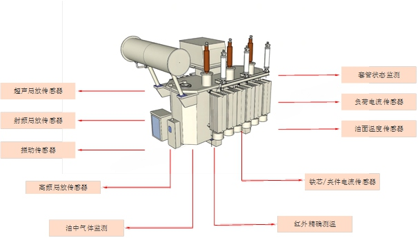
2. Key Engineering Components of Oil-Immersed Power Transformers.
![]()
Understanding the structure is the foundation of effective health management. Failures often originate from the interaction between thermal, विद्युतीय, and mechanical stresses on these internal parts.
2.1. The Magnetic Core Assembly and Low-Loss Lamination
The core is constructed from high-grade, cold-rolled grain-oriented silicon steel laminations to provide a low-reluctance magnetic path. To mitigate parasitic heating, each sheet is coated with a thin insulation layer. The assembly process, involving precise stacking and clamping pressure, is critical for controlling magnetostriction-induced noise and vibration, directly impacting the mechanical integrity monitored by vibration monitoring apparatus.
2.2. The Winding Assembly and Cellulose Insulation System
The windings are copper conductors insulated with paper, forming the most heat-vulnerable component. The design (जैसे, continuous disc for high voltage, helical for low voltage) is chosen to manage short-circuit forces. The paper insulation is the life-limiting factor of the transformer, with its thermal degradation tracked by DGA and the Fluorescence Fiber Optic Sensing apparatus.
2.3. The Oil System: Conservator, Breather, और Radiators
The conservator tank accommodates the volume expansion and contraction of the oil due to temperature changes. The breather uses silica gel to remove moisture from the air entering the conservator, which is essential to prevent moisture ingress into the insulating oil. The radiators and oil pumps constitute the cooling system, managed by the Temperature Monitoring System based on top-oil measurements.
3. Oil-Immersed Distribution Transformers: Classification and Application.
![]()
While sharing a common fundamental design, oil-immersed transformers are classified based on their cooling and the type of insulating fluid used, each impacting their operational profile and required monitoring strategies.
3.1. Classification by Cooling Method (आईईसी 60076)
Cooling methods dictate the transformer’s heat dissipation capacity and short-term overloading capability:
3.1.1. ओनान (Oil Natural, Air Natural)
Relies solely on natural oil circulation and air convection over the radiators. Used for small to medium-sized oil-immersed distribution transformers where initial cost and low maintenance are prioritized.
3.1.2. बंद (Oil Natural, Air Forced)
Adds forced air fans to the radiators to increase the cooling capacity, typically achieving a 30-40% boost in power rating. The fan operation is managed by a controller based on top oil temperature readings from the temperature monitoring apparatus.
3.1.3. OFAF / ODAF (Oil Forced, Air Forced / Directed Flow)
Uses forced oil pumps and fans to achieve the highest cooling efficiency. Essential for very large high-voltage main transformers, often employing directed oil flow to target and cool the winding hot spots directly, making Fluorescence Fiber Optic Sensing particularly crucial.
3.2. Classification by Insulating Fluid
The fluid type determines fire safety and environmental impact, affecting installation location:
3.2.1. Mineral Oil
The traditional and most common fluid due to its excellent electrical properties and low cost. It is flammable and requires fire suppression systems, making it the dominant choice for outdoor substations.
3.2.2. Natural or Synthetic Ester Fluids
These fluids are bio-degradable and possess a high fire point, offering enhanced safety. They are increasingly used in environmentally sensitive areas or indoor installations, providing a safer alternative while retaining the benefits of oil cooling.
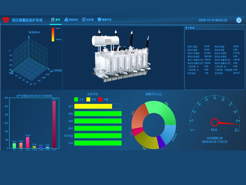
4. The PHM Architecture: Core Modules of a Transformer Health Management System.
A sophisticated Transformer Health Management System (THMS) integrates data from multiple sensing apparatuses to provide a comprehensive state assessment. The architecture is structured into a Sensing Layer, a Communication & Processing Layer, and an Application Layer.
4.1. The Sensing Layer (Data Acquisition)
This layer consists of all the primary sensors and transducers installed directly on the transformer. It includes the PD sensors, DGA apparatus, Fluorescence Fiber Optic sensors, and conventional gauges. Its key role is to accurately convert physical phenomena (गर्मी, गैस, कंपन, electrical discharge) into reliable electrical or optical signals.
4.2. The Processing Layer (Local Intelligence & Data Filtering)
This layer, typically comprising IEDs (Intelligent Electronic Devices) or local data concentrators, performs signal conditioning, data time-stamping, and initial data filtering. Critical functions include calculating trend lines for DGA and applying spectral analysis to PD signals. This layer ensures that the massive data stream is reduced to actionable information before being transmitted to the central system.
4.3. The Application Layer (Diagnostic & Prognostic)
The central monitoring platform, located in the control room or cloud, hosts the THMS software. It applies advanced algorithms (such as Duval Triangles for DGA, and IEC/IEEE thermal models) for fault diagnosis and prognostics. This layer visualizes the transformer’s “स्वास्थ्य सूचकांक” and generates early warning alerts, guiding the operator’s decision-making on predictive maintenance scheduling.
5. Partial Discharge Early Warning System: Multi-Sensor Diagnosis of Insulation Defects.
आंशिक निर्वहन (पी.डी.) is an electrical discharge that only partially bridges the insulation between conductors. It is the most reliable precursor to catastrophic insulation failure. The PD Early Warning System uses a fusion of sensors to achieve high-sensitivity and accurate location.
5.1. Multi-Sensor Deployment Strategy
Effective PD monitoring requires a complementary approach:
5.1.1. High-Frequency Current Transformers (एचएफसीटी)
Installed on the neutral connection or bushings, HFCT sensors capture the high-frequency current pulses generated by PD. They are effective for detecting discharges in the bushing and terminal areas.
5.1.2. Ultra-High Frequency (यूएचएफ) सेंसर
UHF sensors are typically installed via oil drain valves or inspection ports. They capture the electromagnetic waves generated by PD within the oil, offering excellent sensitivity and immunity to external noise, making them ideal for monitoring high-voltage main transformers.
5.1.3. ध्वनिक उत्सर्जन (ऐ) सेंसर
Mounted on the transformer tank walls, AE sensors detect the ultrasonic waves produced by the PD activity. By measuring the Time Difference of Arrival (TDOA) of the sound waves at multiple points, the system can triangulate the precise 3D location of the discharge source (जैसे, in the lower winding assembly or the core).
5.2. Diagnosis and Localization Procedure
The monitoring process involves a critical procedural sequence:
कदम 1: Signal Capture and Filtering
The sensors continuously capture raw data, which is passed through digital filters to suppress external noise (जैसे, radio, ताज). Synchronization with the power frequency is essential to plot the PD activity on the phase cycle (PRPD pattern).
कदम 2: PRPD Pattern Recognition
The Phase-Resolved Partial Discharge (पीआरपीडी) patterns are analyzed to classify the discharge type (जैसे, ताज, void discharge, सतही निर्वहन), which helps infer the physical nature of the defect.
कदम 3: Location Determination
If PD activity is confirmed, the AE sensors’ TDOA data is used to pinpoint the physical location. A confirmed and localized PD trend is a mandatory trigger for a predictive maintenance outage and internal inspection.
6. विघटित गैस विश्लेषण (डीजीए) Apparatus: Real-Time Diagnostic of Internal Thermal Faults.

The Dissolved Gas Analysis (डीजीए) apparatus is the cornerstone of chemical state assessment for oil-immersed power transformers. It provides irrefutable evidence of internal heating, उभरना, or excessive electrical stress.
6.1. Technical Principle of the DGA Apparatus
The online DGA system continuously extracts a small sample of oil, separates the dissolved gases using a membrane or vacuum, and analyzes the concentration of fault gases (H2, CH4, C2H6, C2H4, C2H2, सीओ, CO2) using highly sensitive techniques such as gas chromatography or photo-acoustic spectroscopy. The resulting data is automatically normalized to standard conditions for consistent trending.
6.2. Interpretation Using Diagnostic Ratios
The ratio of specific gases provides the fault signature, following established industry standards:
कदम 1: Gas Concentration Trending
Daily or hourly generation rates are monitored. Any exponential increase in the total combustible gases (TCG) warrants an immediate alert.
कदम 2: Duval Triangle Method
The Duval Triangle method uses the ratios of Methane, ईथीलीन, and Acetylene to definitively classify the fault into categories like low-temperature thermal (T1), high-temperature thermal (T3), or high-energy arcing (D2). This classification is crucial for directing the subsequent fault diagnosis and predictive maintenance action.
कदम 3: Furan Analysis (Advanced Chemical Marker)
Advanced DGA systems also monitor furan compounds, which are direct by-products of cellulose paper degradation. Furan concentration serves as a reliable marker for the consumption of the paper insulation’s useful life.
7. Fluorescence Fiber Optic Sensing: Unrivaled Value in Winding Hot Spot Monitoring.
The Fluorescence Fiber Optic Sensing apparatus is the ultimate solution for measuring the true winding hot spot temperature (HST), which is the direct thermal stress on the paper insulation. This apparatus is indispensable in high-voltage main transformers.
7.1. Technical Imperative: The 6-Degree Aging Rule
Insulation aging follows the Arrhenius Law: for every 6°C temperature rise above the insulation’s reference temperature, the paper life expectancy is halved. Only by knowing the precise HST, which can be 10-20°C higher than the top oil, can operators accurately manage the asset’s thermal consumption and prevent premature aging.
7.2. Why Fiber Optics are Non-Negotiable in Oil-Immersed Transformers
Conventional metallic sensors (Pt100 or thermocouples) cannot be placed inside the high-voltage winding assembly because their metallic leads would compromise the oil/paper insulation structure, leading to catastrophic failure. Fluorescence Fiber Optic Sensors are entirely non-metallic and immune to the intense electromagnetic fields, allowing them to be safely embedded at the HST location during the winding process.
7.3. System Parameters and Deployment Steps
System Specification:
तापमान की रेंज: -40डिग्री सेल्सियस से 260 डिग्री सेल्सियस. शुद्धता: ±1°C. प्रतिक्रिया समय: Less than 1 दूसरा. चैनल क्षमता: 1 को 64 points per processing unit.
Step-by-Step Deployment:
1. Sensor Integration: The fiber optic probe is secured directly onto the copper conductor in the predicted hot spot location (typically the top section of the low-voltage winding). 2. Lead Routing: The fiber is carefully routed out of the winding assembly, ensuring large bend radii to prevent stress. 3. सील: The fiber is sealed via a custom-designed, pressure-resistant feedthrough that maintains the integrity of the oil tank seal. 4. संकेत आगे बढ़ाना: The fiber is connected to the central temperature monitoring apparatus for data acquisition and transmission to the THMS.
8. Bushing Status Assessment System: Predicting Insulation Failure via Composite Sensing.
Bushings are responsible for a significant percentage of explosive transformer failures. The Bushing Status Assessment System uses non-intrusive electrical measurement to evaluate the condition of the internal dielectric.
8.1. Measuring Capacitance and Tan Delta
The system measures the capacitance (सी 1) and the Dielectric Dissipation Factor (तो डेल्टा) of the bushing insulation. Deterioration (जैसे, नमी का प्रवेश, आंशिक निर्वहन गतिविधि) causes both C1 and Tan Delta to increase. By tracking these trends in real-time, the system provides a clear early warning of impending insulation breakdown, allowing for a timely predictive maintenance replacement.
8.2. Principle of Relative Measurement
Often, ए “sum of currents” method is used, where the leakage currents from the three phase bushings are summed. A change in the balance indicates a fault in one specific bushing. The system calculates the individual currents and phase angles to provide a clear and unequivocal diagnosis.
9. Vibration and Acoustic Monitoring: Assessing Winding Clamping and Core Stability.
Mechanical condition is crucial for fault withstand capability. The Vibration and Acoustic Monitoring System tracks the physical state of the core and windings.
9.1. Vibration Signatures and Winding Looseness
The primary vibration is at twice the fundamental frequency (100Hz/120Hz) due to magnetostriction. तथापि, changes in the overall RMS vibration level or the emergence of sideband frequencies indicate mechanical degradation. Looseness in the winding clamping structure is a major concern, as it reduces the ability of the transformer to withstand short-circuit forces, a condition diagnosed by analyzing the vibration spectrum.
9.2. Acoustic Monitoring और Noise Print Analysis
High-sensitivity microphones are used to capture the acoustic signature of the unit. Abnormal sounds like sharp clicking (often associated with PD or OLTC mechanism) or excessive humming (related to core saturation/DC bias) are automatically flagged. The system maintains a historical noise print to immediately identify deviations from normal operating conditions.
10. Core and Clamp Earthing Current Monitoring: Preventing Internal Local Overheating.
The integrity of the internal grounding system is critical for preventing stray currents that cause localized heating. The Core and Clamp Earthing Current Monitoring system utilizes highly sensitive micro-current sensors.
10.1. The Risk of Multi-Point Earthing
The transformer core is designed to be grounded at only one point. The emergence of a second grounding point (जैसे, due to an insulation breakdown between the core and the tank, or a metallic foreign object) creates a closed loop. This loop induces a circulating current, leading to localized overheating of the core steel, which can rapidly accelerate oil decomposition and insulation damage, a condition confirmed by elevated CO and CO2 in DGA data.
10.2. Micro-Current Sensor तकनीकी
Highly sensitive micro-current sensors are placed on the dedicated core and clamp grounding straps. Since the normal current is near zero, any measurable steady-state AC current (typically above 100mA) triggers an immediate early warning. This is a simple yet extremely effective fault diagnosis apparatus for the internal metal structure.
11. Transformer Health Status Assessment: Common Failure Modes and Diagnostic Signatures.
The goal of the THMS is to fuse data from all subsystems to achieve a reliable and holistic status assessment. Failure modes are categorized by their origin.
11.1. Thermal Faults and DGA Signatures
These are the most common faults, typically caused by excessive loading, poor cooling, or poor contacts.
Diagnosis Procedure:
1. कदम 1 (Confirmation): Fluorescence Fiber Optic Sensing confirms actual winding temperature is excessive, or DGA shows high levels of Ethylene (C2H4) and Methane (CH4) (thermal over 700°C).
2. कदम 2 (Root Cause): Top Oil/Bottom Oil temperature differential suggests cooling inefficiency, or the Core Earthing Current Monitor indicates localized heating from circulating currents.
11.2. Electrical Faults and Dielectric Signatures
These faults include partial discharge, उभरना, and insulation breakdown.
Diagnosis Procedure:
1. कदम 1 (Detection): PD Early Warning System (UHF/AE) reports sustained activity, and/or DGA shows high levels of Acetylene (C2H2) (arcing/high-energy fault).
2. कदम 2 (जगह): AE sensors provide a 3D location estimate. A corresponding jump in the Bushing Status Assessment Tan Delta value points to a fault in the terminal connection area.
11.3. Mechanical Faults and Acoustic Signatures
These faults relate to structural degradation, mainly affecting short-circuit withstand capability.
Diagnosis Procedure:
1. कदम 1 (Initial Alert): Vibration and Acoustic Monitoring reports an increase in non-fundamental frequencies or a significant deviation from the established noise baseline.
2. कदम 2 (Confirmation): Correlating the vibration anomaly with the OLTC Status Monitor data confirms whether the issue is a tap changer mechanism fault or actual winding/core looseness. No DGA activity suggests the fault is purely mechanical.
12. Quantifiable ROI: The Business Case for Prognostics and Health Management (PHM).
The investment in a comprehensive PHM system for तेल में डूबे बिजली ट्रांसफार्मर is justified by significant returns in asset protection and operational efficiency.
12.1. अधिकतम Asset Life Expectancy और Insulation Assessment
By continuously monitoring the HST via Fluorescence Fiber Optic Sensing, operators avoid the “6-Degree Rule” penalty, extending the life of the cellulose insulation. The PHM system generates a true Insulation Health Index, optimizing the asset’s predictive maintenance schedule and extending the time between major overhauls.
12.2. सक्षम करने से Safe Dynamic Rating और Load Optimization
Knowing the actual HST allows for safe dynamic loading beyond the nameplate rating when the ambient temperature is low. This feature avoids unnecessary investment in new infrastructure simply to meet peak demand, a crucial benefit for oil-immersed distribution transformers serving fluctuating urban loads.
12.3. Reducing रखरखाव लागत और Forced Outages
The ability of the PHM system to provide early warning of faults (जैसे, PD or DGA spikes) allows operators to schedule repairs during non-critical periods. This transition from costly reactive maintenance to planned, predictive maintenance drastically reduces labor costs and eliminates the enormous financial penalty associated with forced outages.
अक्सर पूछे जाने वाले प्रश्न: Oil-Immersed Transformer PHM and पूर्वानुमानित रखरखाव.
These common questions address the technical and operational aspects of maintaining high-voltage power transformers.
Questions on Oil-Immersed Transformer Operation:
Q1. Why is the winding hot spot temperature (HST) more critical than top oil temperature?
ए: The HST is the highest temperature point in the entire transformer, typically found in the upper winding section. Since insulation aging is an exponential function of temperature, the HST is the primary determinant of the transformer’s life. Top oil temperature is a bulk measurement that can lag HST by 10°C to 20°C, making it an inadequate parameter for safe dynamic loading.
Q2. What is the standard temperature limit for the top oil in a main power transformer?
ए: According to IEC standards, the top oil temperature is typically limited to 95°C (alarm at 85°C), while the HST limit is usually 98°C or 105°C depending on the insulation class. Exceeding these limits, even briefly, activates the “6-Degree Rule” and significantly accelerates paper degradation.
Q3. Does the use of ester oil in an तेल में डूबा ट्रांसफार्मर change the required monitoring strategy?
ए: Ester oils have a higher fire point and are environmentally friendly, but the PHM strategy remains the same. The DGA interpretation may require specialized gas coefficients, and the Fiber Optic Sensing is equally critical, as the insulation paper (the solid dielectric) is still the life-limiting component.
Q4. How does the cooling system (ONAN vs. OFAF) affect the status assessment?
ए: OFAF systems use forced pumps and fans, meaning a failure in the Cooling System Monitoring apparatus can lead to immediate, rapid temperature excursions. The status assessment for OFAF must incorporate pump motor current and fan speed data to ensure the heat removal capability is intact.
Questions on PHM and Early Warning Systems:
Q5. What is the most reliable fault precursor detected by a predictive maintenance apparatus?
ए: The most critical precursors are sustained Partial Discharge (पी.डी.) activity and rapidly rising Acetylene (C2H2) gas levels in the DGA. Both indicate high-energy electrical breakdown that can lead to explosion, making the PD Early Warning System and DGA Apparatus indispensable.
Q6. How is the data from the Bushing Status Assessment System used in PHM?
ए: The system provides a crucial time-to-failure estimate. A significant, sustained increase in Tan Delta (Dielectric Dissipation Factor) is a high-priority alarm that dictates a mandatory, scheduled outage for bushing replacement, preventing a costly and dangerous catastrophic failure.
क्यू 7. Can the Vibration Monitoring System detect OLTC faults?
ए: हाँ. The Vibration Monitoring System is highly effective at diagnosing On-Load Tap Changer (ओएलटीसी) faults. It analyzes the mechanical ‘bump’ signature during tap changes. Deviations from the baseline signature indicate mechanical issues like poor spring tension, contact wear, or improper sequencing of the diverter switch.
Q8. Why is the Core Earthing Current only an AC current?
ए: The core should only ever experience an induced AC voltage if a second ground is present, creating an AC circulating current (Eddy Current). A significant DC current on the ground strap would indicate a separate external DC path, but the AC component is the signature of the internal multi-point earthing fault.
Questions on Fluorescence Fiber Optic Sensing:
प्रश्न 9. What are the advantages of Fluorescence Fiber Optic Sensors over Infrared (और) कैमरा?
ए: IR cameras can only measure the external tank or terminal surface temperature, which is a poor proxy for the internal winding temperature. Fiber Optic Sensors are physically embedded inside the winding to measure the true hot spot, providing highly accurate and immediate data essential for health management. They are also immune to tank emissivity and environmental changes.
Q10. Is the high accuracy (±1°C) of the Fiber Optic System necessary for a large transformer?
ए: हाँ, the high accuracy is essential. Given the 6-Degree Aging Rule, even a 1°C measurement error can lead to a 10% को 15% error in the calculated remaining life of the transformer. High precision ensures accurate status assessment and prevents the premature aging of the paper insulation.
Q11. कर सकना Fluorescence Fiber Optic Sensors be installed on a transformer already in service?
ए: Installation typically requires draining the oil and lifting the core/winding assembly out of the tank (a major overhaul). While possible, it is most cost-effective to specify and install Fiber Optic Sensing during the initial manufacturing phase of a new oil-immersed power transformer.
Q12. How many sensing channels are typically required for a High-Voltage Main Transformer?
ए: A minimum of 6 को 9 channels is recommended: one for the HST of each of the three phases (HV or LV winding, depending on design), and others for the core and top/bottom oil to provide a complete thermal profile. Our temperature monitoring apparatus is capable of integrating up to 64 channels for comprehensive coverage.
Acquire High-Voltage Transformer Monitoring Solutions और Sensing Apparatus.
Securing the operational integrity of your oil-immersed power transformers requires more than just reactive maintenance—it demands a robust Prognostics and Health Management (PHM) strategy.
We provide full-spectrum monitoring and early warning solutions, शामिल:
- Embedded Fluorescence Fiber Optic Sensing systems for true HST measurement.
- Integrated DGA Apparatus and Partial Discharge Early Warning Systems.
- Custom PHM software platforms for holistic transformer health status assessment and predictive maintenance scheduling.
Please contact our engineering team via our website to request a detailed technical proposal, specification sheets, and a competitive quotation for your next high-voltage project.

फाइबर ऑप्टिक तापमान सेंसर, बुद्धिमान निगरानी प्रणाली, चीन में वितरित फाइबर ऑप्टिक निर्माता
 |
 |
 |