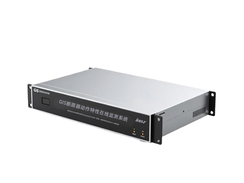
 INNO फाइबर ऑप्टिक तापमान सेंसर ,तापमान निगरानी प्रणाली.
गैस रोकने वाला बटनयंत्र (गिस) दुनिया भर में आधुनिक विद्युत पारेषण और वितरण नेटवर्क की रीढ़ बन गया है. उच्च वोल्टेज पर काम करने वाले महत्वपूर्ण बुनियादी ढांचे के घटकों के रूप में, जीआईएस उपकरण विनाशकारी विफलताओं को रोकने के लिए निरंतर निगरानी की आवश्यकता है, परिचालन विश्वसनीयता सुनिश्चित करें, और रखरखाव रणनीतियों को अनुकूलित करें. यह व्यापक मार्गदर्शिका इसकी पड़ताल करती है जीआईएस दोष चेतावनी और निगरानी प्रणाली, पता लगाने वाली प्रौद्योगिकियों को कवर करना, सेंसर आर्किटेक्चर, संचार प्रोटोकॉल, और उपयोगिताओं के लिए व्यावहारिक कार्यान्वयन रणनीतियाँ, बिजली संयंत्र संचालक, और औद्योगिक सुविधाएं.
- प्राथमिक अनुप्रयोग परिदृश्य: अतिरिक्त-उच्च वोल्टेज सबस्टेशन, शहरी वितरण नेटवर्क, बिजली उत्पादन सुविधाएं, औध्योगिक संयंत्र, अपतटीय पवन प्लेटफार्म, और रेलवे विद्युतीकरण प्रणाली
- मुख्य तकनीकी लाभ: वास्तविक समय स्थिति का आकलन, शीघ्र दोष का पता लगाना, पूर्वानुमानित रखरखाव क्षमताएँ, डाउनटाइम कम हो गया, उन्नत सुरक्षा प्रोटोकॉल, और पर्यावरण नियमों का अनुपालन
- सिस्टम आर्किटेक्चर घटक: मल्टी-पैरामीटर सेंसर नेटवर्क, बुद्धिमान डेटा अधिग्रहण इकाइयाँ, औद्योगिक संचार अवसंरचना, केंद्रीकृत निगरानी मंच, और स्वचालित अलार्म प्रबंधन प्रणाली
- मॉनिटर किए गए पैरामीटर: आंशिक निर्वहन गतिविधि, SF6 गैस घनत्व और शुद्धता, तापमान वितरण, यांत्रिक परिचालन विशेषताएँ, नमी की मात्रा, गैस अपघटन उपोत्पाद, और पर्यावरणीय स्थितियाँ
- संचार और डेटा अवसंरचना: आईईसी 61850 प्रोटोकॉल कार्यान्वयन, मोडबस आरटीयू/टीसीपी कनेक्टिविटी, फाइबर ऑप्टिक नेटवर्क, औद्योगिक ईथरनेट रीढ़, वायरलेस टेलीमेट्री विकल्प, और साइबर सुरक्षा ढाँचे
- चेतावनी और चेतावनी कार्य: बहु-स्तरीय अलार्म पदानुक्रम, सीमा-आधारित सूचनाएं, प्रवृत्ति विश्लेषण चेतावनियाँ, असामान्य पैटर्न पहचान, मोबाइल पुश सूचनाएं, और SCADA सिस्टम के साथ एकीकरण
- रखरखाव लाभ: समय-आधारित से स्थिति-आधारित रखरखाव में परिवर्तन, विस्तारित उपकरण जीवन काल, अनुकूलित निरीक्षण कार्यक्रम, परिचालन लागत में कमी, बेहतर ग्रिड विश्वसनीयता, और व्यापक विफलता विश्लेषण डेटाबेस
1. जीआईएस क्या है? (गैस रोकने वाला बटनयंत्र)
1.1 जीआईएस की बुनियादी अवधारणाएं और संचालन सिद्धांत
गैस रोकने वाला बटनयंत्र (गिस) एक कॉम्पैक्ट हाई-वोल्टेज विद्युत सबस्टेशन तकनीक का प्रतिनिधित्व करता है जहां सभी प्राथमिक स्विचिंग और सुरक्षा उपकरण सल्फर हेक्साफ्लोराइड से भरे सीलबंद धातु डिब्बों में संलग्न होते हैं (SF6) गैस. वही SF6 इंसुलेटिंग गैस दोहरे उद्देश्य को पूरा करता है: लगभग बेहतर ढांकता हुआ इन्सुलेशन शक्ति प्रदान करना 2-3 वायुमंडलीय दबाव पर हवा से कई गुना अधिक, और सर्किट ब्रेकर संचालन के दौरान आर्क-शमन माध्यम के रूप में कार्य करता है. ठेठ जीआईएस असेंबली सर्किट ब्रेकरों को एकीकृत करता है, स्विच डिस्कनेक्ट करें, ग्राउंडिंग स्विच, वर्तमान ट्रांसफार्मर, वोल्टेज ट्रांसफार्मर, और एकल धातु-संलग्न संरचना के भीतर बसबार.
परिचालन सिद्धांत SF6 गैस के असाधारण विद्युत गुणों पर निर्भर करता है. से लेकर दबावों पर 0.4 तक 0.6 एमपीए (4-6 छड़), SF6 गैस कई गुना वायुमंडलीय दबाव पर हवा के बराबर इन्सुलेशन प्रदान करती है, नाटकीय रूप से स्थान में कमी को सक्षम करना. गैस अणुओं में उत्कृष्ट इलेक्ट्रॉन-कैप्चरिंग विशेषताएं होती हैं, तेजी से मुक्त इलेक्ट्रॉनों को निष्क्रिय करना जो अन्यथा विद्युत विखंडन शुरू कर सकता है. दौरान सर्किट ब्रेकर स्विचिंग ऑपरेशन, SF6 गैस प्रवाह थर्मल और ढांकता हुआ शीतलन प्रक्रियाओं के माध्यम से विद्युत चाप को बुझा देता है, आम तौर पर मिलीसेकेंड के भीतर.
1.2 जीआईएस प्रौद्योगिकी का विकास इतिहास
का विकास जीआईएस प्रौद्योगिकी इसकी शुरुआत 1960 के दशक में हुई जब उपयोगिताओं को शहरी क्षेत्रों में भूमि की बढ़ती लागत और जगह की कमी का सामना करना पड़ा. प्रारंभिक जीआईएस संस्थापन ट्रांसमिशन वोल्टेज पर संचालित होते थे 72.5 केवी को 145 के.वी, मुख्य रूप से जापान और यूरोप में तैनात किया गया. 1970-1980 के दशक के दौरान, निर्माताओं ने जीआईएस क्षमताओं का विस्तार किया 245 के.वी, 420 के.वी, और 550 केवी वोल्टेज कक्षाएं, बेहतर SF6 गैस हैंडलिंग सिस्टम और बेहतर इंसुलेटर डिज़ाइन को शामिल करना.
1990 के दशक में महत्वपूर्ण तकनीकी प्रगति देखी गई जिसमें इसकी शुरूआत भी शामिल थी अति उच्च वोल्टेज (यूएचवी) गिस पर मूल्यांकित किया गया 800 केवी और 1100 चीन में लंबी दूरी की ट्रांसमिशन परियोजनाओं के लिए के.वी, जापान, और रूस. आधुनिक चौथी पीढ़ी के जीआईएस उपकरण में मॉड्यूलर निर्माण की सुविधा है, एकीकृत निगरानी क्षमताएँ, न्यूनतम SF6 गैस उत्सर्जन के साथ पर्यावरण-अनुकूल डिज़ाइन, और आईईसी के साथ संगत डिजिटल सेकेंडरी सिस्टम 61850 संचार मानक.
1.3 जीआईएस बनाम पारंपरिक एयर-इंसुलेटेड स्विचगियर (एआईएस) तुलना
| तुलना पैरामीटर | गिस (गैस रोकने वाला बटनयंत्र) | एआईएस (एयर इंसुलेटेड स्विचगियर) |
|---|---|---|
| जगह की जरूरतें | लगभग 10-20% समतुल्य AIS पदचिह्न का; विशिष्ट 245kV बे की आवश्यकता होती है 40-60 वर्ग मीटर | व्यापक बाहरी क्षेत्र की आवश्यकता; विशिष्ट 245kV बे की आवश्यकता होती है 300-500 वर्ग मीटर |
| स्थापना स्थान | इनडोर या आउटडोर; भूमिगत सबस्टेशनों के लिए आदर्श, शहरी केंद्र, अपतटीय प्लेटफार्म | मुख्य रूप से पर्याप्त निकासी दूरी के साथ बाहरी स्थापना |
| इन्सुलेशन माध्यम | SF6 गैस और 0.4-0.6 एमपीए दबाव; बेहतर ढांकता हुआ ताकत | वायुमंडलीय वायु; चरण-दर-चरण और चरण-दर-ग्राउंड मंजूरी की आवश्यकता होती है |
| रखरखाव आवश्यकताएँ | न्यूनतम; सीलबंद डिब्बे संदूषण को रोकते हैं; विशिष्ट निरीक्षण अंतराल 5-10 साल | नियमित रखरखाव आवश्यक है; मौसम से प्रभावित खुले उपकरण, प्रदूषण, जानवर |
| विश्वसनीयता और उपलब्धता | उच्च विश्वसनीयता (99.9%+); कम विफलता दर; पर्यावरणीय कारकों से सुरक्षित | मौसम पर निर्भर विश्वसनीयता; संदूषण या गंभीर मौसम के दौरान फ्लैशओवर |
| सुरक्षा संबंधी विचार | बढ़ी हुई कार्मिक सुरक्षा; संलग्न ऊर्जावान हिस्से; कम आर्क फ़्लैश एक्सपोज़र | उच्च सुरक्षा जोखिम; उजागर उच्च-वोल्टेज कंडक्टर; पक्षी/जानवरों के घुसपैठ के खतरे |
| प्रारंभिक पूंजी लागत | उच्च उपकरण लागत; 1.5-2.5 वोल्टेज वर्ग के आधार पर एआईएस उपकरण की लागत का समय | कम उपकरण लागत; शहरी क्षेत्रों में उच्च सिविल कार्य और भूमि अधिग्रहण लागत |
| जीवनचक्र लागत | स्वामित्व की कम कुल लागत; कम रखरखाव, उच्च विश्वसनीयता, छोटा पदचिह्न | अधिकांश अनुप्रयोगों में उच्च जीवनचक्र लागत; लगातार रखरखाव, अधिक भूमि उपयोग |
| पर्यावरणीय प्रभाव | नियंत्रित SF6 उत्सर्जन (शक्तिशाली ग्रीनहाउस गैस); आधुनिक डिज़ाइन रिसाव को कम करते हैं <0.5% प्रतिवर्ष | न्यूनतम प्रत्यक्ष उत्सर्जन; बड़ी भूमि गड़बड़ी; परिदृश्यों में दृश्य प्रभाव |
| भूकंपीय प्रदर्शन | उत्कृष्ट भूकंपरोधी; कॉम्पैक्ट कठोर संरचना; उच्च भूकंपीय क्षेत्रों के लिए उपयुक्त | भूकंपीय घटनाओं के प्रति अधिक संवेदनशील; एकाधिक समर्थन संरचनाएँ; लंबे कंडक्टर |
| विस्तार क्षमता | मॉड्यूलर डिज़ाइन नियंत्रित विस्तार की अनुमति देता है; अतिरिक्त खाड़ी के लिए अग्रिम योजना की आवश्यकता है | यदि भूमि उपलब्ध हो तो क्षैतिज विस्तार आसान है; उपकरण जोड़ना आसान |
| विद्युत चुम्बकीय हस्तक्षेप | धातु के बाड़े विद्युत चुम्बकीय परिरक्षण प्रदान करते हैं; ईएमआई उत्सर्जन में कमी | उच्च विद्युत चुम्बकीय क्षेत्र स्तर; आस-पास के इलेक्ट्रॉनिक्स के साथ संभावित हस्तक्षेप |
1.4 जीआईएस वोल्टेज वर्ग वर्गीकरण
मध्यम वोल्टेज जीआईएस पर कार्य करता है 12 केवी को 40.5 के.वी, आमतौर पर औद्योगिक सुविधाओं में तैनात किया जाता है, वाणिज्यिक भवन, और वितरण सबस्टेशन. उच्च वोल्टेज जीआईएस से लेकर 72.5 केवी को 170 क्षेत्रीय ट्रांसमिशन नेटवर्क के लिए केवी. अतिरिक्त-उच्च वोल्टेज (ईएचवी) गिस तक फैला 245 केवी को 550 थोक विद्युत पारेषण के लिए के.वी. अति उच्च वोल्टेज (यूएचवी) गिस पर 800 केवी और 1100 केवी वर्तमान प्रौद्योगिकी के शिखर का प्रतिनिधित्व करता है, चीन के राष्ट्रीय ट्रांसमिशन ग्रिड और लंबी दूरी की आवश्यकता वाली चुनिंदा अंतरराष्ट्रीय परियोजनाओं में उपयोग किया जाता है, न्यूनतम हानि के साथ उच्च क्षमता वाली बिजली वितरण.
2. जीआईएस उपकरण के लिए प्राथमिक अनुप्रयोग क्षेत्र
2.1 अतिरिक्त-उच्च वोल्टेज और अल्ट्रा-उच्च वोल्टेज सबस्टेशन
ईएचवी और यूएचवी ट्रांसमिशन सबस्टेशन जीआईएस प्रौद्योगिकी के लिए सबसे अधिक मांग वाले अनुप्रयोग वातावरण का प्रतिनिधित्व करते हैं. के वोल्टेज स्तर पर 245 के.वी, 420 के.वी, 550 के.वी, 800 के.वी, और 1100 के.वी, जीआईएस इंस्टॉलेशन राष्ट्रीय और क्षेत्रीय पावर ग्रिड के लिए महत्वपूर्ण स्विचिंग बुनियादी ढांचे का निर्माण करते हैं. इन सबस्टेशनों में आमतौर पर कई ट्रांसफार्मर खण्ड होते हैं, व्यापक बस विन्यास (double-bus, ring-bus, or breaker-and-a-half arrangements), and sophisticated protection schemes.
वही जीआईएस निगरानी प्रणाली in EHV/UHV applications must address unique challenges including higher insulation stress levels, more severe consequences of equipment failure, and extended maintenance intervals due to accessibility constraints. Monitoring equipment specifications require enhanced sensitivity for partial discharge detection, high-precision SF6 density measurement with temperature compensation, and comprehensive mechanical diagnostics to detect subtle degradation in circuit breaker operating mechanisms before catastrophic failure occurs.
2.2 Urban Center Distribution Substations
Metropolitan areas face severe land constraints, निर्माण compact GIS substations the preferred solution for 72.5 केवी को 145 kV distribution networks. ये प्रतिष्ठान अक्सर पार्कों के नीचे भूमिगत स्थानों पर कब्जा कर लेते हैं, वाणिज्यिक विकास, या परिवहन अवसंरचना. वही इनडोर जीआईएस कॉन्फ़िगरेशन न्यूनतम निकासी दूरी की आवश्यकता समाप्त हो जाती है, बहुमंजिला ऊर्ध्वाधर निर्माण को सक्षम बनाता है, और मौसम-स्वतंत्र संचालन प्रदान करता है.
शहरी जीआईएस स्थापनाओं से काफी लाभ होता है ऑनलाइन निगरानी प्रणाली क्योंकि अस्पतालों जैसे महत्वपूर्ण भार की सेवा देने वाले नेटवर्क में निर्धारित रखरखाव विंडो प्राप्त करना मुश्किल है, डेटा केंद्र, वित्तीय जिले, और जन परिवहन प्रणालियाँ. वास्तविक समय की निगरानी स्थिति-आधारित रखरखाव रणनीतियों को सक्षम बनाती है जो घनी आबादी वाले क्षेत्रों में सार्वजनिक सुरक्षा सुनिश्चित करते हुए उपकरण उपलब्धता को अधिकतम करती है.
2.3 विद्युत उत्पादन संयंत्र स्विचयार्ड
जेनरेटर स्टेप-अप (जीएसयू) ट्रांसफार्मर और स्विचयार्ड जीआईएस थर्मल पर, नाभिकीय, पनबिजली, और नवीकरणीय ऊर्जा बिजली संयंत्र जनरेटर वोल्टेज स्तर से संक्रमण को संभालते हैं (आम तौर पर 13.8-24 के.वी) ट्रांसमिशन वोल्टेज के लिए. ये इंस्टॉलेशन यूनिट स्टार्टअप के दौरान बार-बार स्विचिंग ऑपरेशन का अनुभव करते हैं, तुल्यकालन, और शटडाउन अनुक्रम, साथ ही स्थिर-अवस्था पीढ़ी के दौरान निरंतर संचालन.
वही जीआईएस निगरानी आवश्यकताएँ उत्पादन सुविधाओं में सर्किट ब्रेकरों और डिस्कनेक्ट स्विचों पर यांत्रिक घिसाव ट्रैकिंग पर जोर दिया जाता है, उच्च-वर्तमान कनेक्शनों की तापमान निगरानी, और SF6 गैस गुणवत्ता मूल्यांकन. कई संयंत्र एकीकृत निगरानी प्रणाली लागू करते हैं जो जनरेटर ऑपरेटिंग मापदंडों के साथ जीआईएस प्रदर्शन डेटा को सहसंबंधित करते हैं, ट्रांसफार्मर लोड हो रहा है, और नियोजित कटौती के आसपास रखरखाव शेड्यूलिंग को अनुकूलित करने के लिए ग्रिड प्रेषण निर्देश.
2.4 औद्योगिक विद्युत वितरण प्रणाली
स्टील मिलों सहित बड़े औद्योगिक परिसर, पेट्रोकेमिकल रिफाइनरियाँ, सीमेंट संयंत्र, खनन कार्य, और विनिर्माण सुविधाएं तैनात हैं मध्यम-वोल्टेज जीआईएस (12-40.5 के.वी) आने वाली उपयोगिता फ़ीड के लिए, ऑन-साइट जनरेशन इंटरकनेक्शन, और महत्वपूर्ण प्रक्रिया भार वितरण. कॉम्पैक्ट फ़ुटप्रिंट उन पौधों के वातावरण के लिए उपयुक्त है जहां उत्पादन फ़्लोर स्थान उच्च आर्थिक मूल्य रखता है.
औद्योगिक जीआईएस निगरानी प्रणाली संयंत्र वितरित नियंत्रण प्रणालियों के साथ एकीकृत करें (विकास) और विनिर्माण निष्पादन प्रणाली (एमईएस) उत्पादन प्रक्रियाओं के साथ विद्युत स्विचिंग का समन्वय करना. निगरानी की प्राथमिकताओं में उत्पादन व्यवधानों को कम करने के लिए तेजी से दोष का पता लगाना शामिल है, स्वच्छ विनिर्माण वातावरण में संदूषण की रोकथाम, और खतरनाक क्षेत्रों में सुरक्षा अनुपालन जहां विस्फोटक वातावरण मौजूद हो सकता है.
3. सामान्य जीआईएस विफलता मोड और तंत्र
3.1 इन्सुलेशन विफलता श्रेणियाँ
3.1.1 आंशिक निर्वहन गिरावट
आंशिक निर्वहन (पी.डी.) गतिविधि represents localized electrical discharges that partially bridge the insulation between conductors without causing complete breakdown. PD occurs at defect sites including sharp metallic protrusions, free conducting particles, insulator surface contamination, or gas voids in solid insulation. Each discharge event deposits energy that gradually erodes insulating materials through electrochemical processes and thermal effects.
वही PD degradation mechanism accelerates over time as initial micro-damage creates increasingly favorable conditions for discharge activity. Common PD sources in GIS include manufacturing defects (metal particles left during assembly), installation problems (contamination introduced during commissioning), और परिचालन तनाव (mechanical vibration loosening internal components). यूएचएफ आंशिक निर्वहन निगरानी इन्सुलेशन विफलता को पूरा करने के लिए आगे बढ़ने से वर्षों पहले इन दोषों का पता लगाता है, जबरन आपातकालीन मरम्मत के बजाय निर्धारित कटौती के दौरान नियोजित हस्तक्षेप को सक्षम करना.
3.1.2 SF6 गैस अपघटन प्रभाव
विद्युत निर्वहन घटनाओं या थर्मल दोषों के दौरान, SF6 गैस विघटित हो जाती है सल्फर टेट्राफ्लोराइड सहित विभिन्न उपोत्पादों में (SF4), सल्फर डाइऑक्साइड (SO2), थियोनिल फ्लोराइड (SOF2), और सल्फ्यूरिल फ्लोराइड (SO2F2). ये यौगिक थोड़ी नमी के साथ प्रतिक्रिया करके हाइड्रोफ्लोरिक एसिड बनाते हैं (एचएफ) और अन्य संक्षारक पदार्थ जो इन्सुलेटर सतहों पर हमला करते हैं, धातु घटक, और सीलेंट सामग्री.
की उपस्थिति SF6 अपघटन उत्पाद सक्रिय या हालिया डिस्चार्ज गतिविधि को इंगित करता है. निगरानी प्रणालियाँ इन गैसों का प्रति मिलियन भाग सांद्रता पर पता लगाती हैं, providing chemical evidence of insulation problems that may not yet produce detectable partial discharges under normal operating voltage. Gas analysis complements electrical PD detection methods, offering convergent evidence for diagnostic decision-making.
3.2 यांत्रिक विफलताएँ
3.2.1 Operating Mechanism Malfunctions
सर्किट ब्रेकर ऑपरेटिंग तंत्र employ spring-charged energy storage, हाइड्रोलिक सिस्टम, or pneumatic actuators to drive the moving contacts during opening and closing operations. Mechanical failures occur due to lubrication degradation, वसंत की थकान, seal leakage in hydraulic/pneumatic systems, linkage wear, or control valve malfunctions.
Symptoms of mechanism degradation include increasing operating times, reduced contact travel velocity, incomplete stroke completion, and excessive operating energy consumption. Mechanical monitoring systems track travel-time curves, ऑपरेटिंग कुंडल धाराओं को मापें, और ब्रेकर के संचालन में विफलता का कारण बनने से पहले विकासशील समस्याओं की पहचान करने के लिए कंपन हस्ताक्षरों का विश्लेषण करें (एफटीओ) या यात्रा करने में विफलता (एफटीटी) महत्वपूर्ण स्विचिंग ऑपरेशन के दौरान घटनाएँ.
3.2.2 संपर्क घिसाव और कटाव
संपर्कों को आर्किंग करना जीआईएस सर्किट ब्रेकरों में प्रत्येक स्विचिंग ऑपरेशन के दौरान उच्च-ऊर्जा विद्युत चाप के कारण सामग्री का क्षरण होता है, जो लोड के तहत संपर्कों के अलग होने पर बनता है।. संपर्क सामग्री (आमतौर पर तांबा-टंगस्टन या अन्य दुर्दम्य धातु मिश्र धातु) धीरे-धीरे वाष्पीकृत होकर इन्सुलेटर सतहों पर जमा हो जाता है, संभावित रूप से संचालन पथ बनाना.
वही संपर्क क्षरण दर स्विचित वर्तमान परिमाण पर निर्भर करता है, संचालन की कुल संख्या, सर्किट पावर फैक्टर, और कर्तव्य चक्र बदलना. मॉनिटरिंग सिस्टम शेष संपर्क जीवन का अनुमान लगाने के लिए संचयी संचालन और स्विच किए गए एम्पीयर-घंटे को ट्रैक करते हैं. तापमान की निगरानी से क्षरण बढ़ने पर बढ़े हुए संपर्क प्रतिरोध से असामान्य ताप का पता चलता है, नियोजित रखरखाव के दौरान सक्रिय संपर्क प्रतिस्थापन को सक्षम करना.
3.3 SF6 गैस रिसाव
SF6 गैस रिसाव इन्सुलेशन शक्ति और व्यवधान क्षमता को कम करता है, यदि गैस घनत्व न्यूनतम परिचालन सीमा से कम हो जाता है तो संभावित रूप से उपकरण विफलता हो सकती है. लीक स्रोतों में बोल्टेड फ्लैंज पर सील का क्षरण शामिल है, समय के साथ गैसकेट संपीड़न सेट, वेल्ड या कास्टिंग में सूक्ष्म दरारें, वाल्व स्टेम पैकिंग घिसाव, और धातु के बाड़ों में संक्षारण-प्रेरित गड्ढे.
आधुनिक जीआईएस रिसाव दर विनिर्देश आमतौर पर इससे कम जनादेश मिलता है 0.5% प्रति सीलबंद डिब्बे में वार्षिक रिसाव. ऑनलाइन गैस घनत्व निगरानी प्रणाली दबाव और तापमान को लगातार ट्रैक करें, वास्तविक समय घनत्व मूल्यों की गणना करना और मैन्युअल निरीक्षण के बीच महीनों की प्रतीक्षा करने के बजाय दिनों के भीतर लीक का पता लगाना. पर्यावरण SF6 एकाग्रता सेंसर बड़ी लीक का तुरंत पता लगाते हैं, सीमित जीआईएस कमरों में दम घुटने के खतरों को रोकने के लिए वेंटिलेशन सिस्टम और कार्मिक अलार्म को सक्रिय करना.
3.4 ज़्यादा गरम होने की विफलता
जीआईएस में थर्मल दोष बोल्ट वाले जोड़ों पर उच्च-प्रतिरोध कनेक्शन से उत्पन्न होता है, फिसलने वाले संपर्कों पर अपर्याप्त संपर्क दबाव, बाड़ों में भंवर धारा तापन, या स्थानीयकृत इन्सुलेशन क्षरण. एयर-इंसुलेटेड उपकरण के विपरीत जहां दृश्य निरीक्षण से कनेक्शन का रंग फीका पड़ जाता है, जीआईएस थर्मल समस्याएं सीलबंद डिब्बों के अंदर छिपी हुई विकसित होती हैं.
तापमान निगरानी प्रणाली महत्वपूर्ण कनेक्शन बिंदुओं पर स्थापित फाइबर ऑप्टिक सेंसर या वायरलेस तापमान ट्रांसमीटर का उपयोग करके स्थायी क्षति होने से पहले तापमान वृद्धि के रुझान का पता लगाया जाता है. उन्नत इंस्टॉलेशन वितरित तापमान सेंसिंग फाइबर ऑप्टिक केबलों को नियोजित करते हैं जो बसबारों और कई कनेक्शन बिंदुओं पर निरंतर तापमान प्रोफाइल प्रदान करते हैं, मीटर-स्तरीय स्थानिक रिज़ॉल्यूशन के साथ हॉटस्पॉट की पहचान करना.
4. जीआईएस उपकरण घटक और संरचना
4.1 प्राथमिक विद्युत उपकरण
4.1.1 सर्किट ब्रेकर इकाइयाँ
जीआईएस सर्किट ब्रेकर स्विचिंग आर्क को बुझाने के लिए SF6 गैस प्रवाह का उपयोग करते हुए पफ़र-प्रकार या सेल्फ-ब्लास्ट आर्क रुकावट तंत्र का उपयोग करें. वही पफ़र ब्रेकर डिज़ाइन उद्घाटन संचालन के दौरान SF6 गैस को संपीड़ित करने के लिए यांत्रिक रूप से संचालित पिस्टन का उपयोग करता है, आर्क कॉलम को ठंडा और डी-आयनीकृत करने के लिए अलग-अलग संपर्कों में उच्च-वेग गैस प्रवाह को निर्देशित करना. स्व-विस्फोट तोड़ने वाले हीटिंग वॉल्यूम में SF6 गैस को गर्म करने और दबाव डालने के लिए आर्क ऊर्जा का ही उपयोग करें, दबाव अंतर बनाना जो चाप क्षेत्र के माध्यम से गैस प्रवाह को संचालित करता है.
आधुनिक डेड-टैंक जीआईएस ब्रेकर सभी जीवित भागों को जमी हुई धातु के बाड़ों में बंद करें, सुरक्षा बढ़ाना और निकटवर्ती उपकरणों से निकटता को सक्षम बनाना. वही अवरोधक इकाई इसमें गतिशील और स्थिर संपर्क शामिल हैं, चाप नियंत्रण नलिका, और इंसुलेटिंग नोजल जो गैस प्रवाह पैटर्न को आकार देते हैं. निगरानी आवश्यकताएँ यांत्रिक यात्रा विशेषताओं पर केंद्रित हैं, परिचालन ऊर्जा खपत, संपर्क प्रतिरोध, और अवरोधक क्षेत्र में आंशिक निर्वहन का पता लगाना.
4.1.2 डिस्कनेक्ट और चयनकर्ता स्विच
स्विच डिस्कनेक्ट करें (आइसोलेटरों) जब रखरखाव कार्य के लिए विशिष्ट उपकरणों को डी-एनर्जेटिक करने की आवश्यकता होती है, तो जीआईएस दृश्यमान अलगाव बिंदु प्रदान करता है. सर्किट ब्रेकर के विपरीत, डिस्कनेक्ट स्विच लोड करंट या फॉल्ट करंट को बाधित नहीं कर सकते; वे तभी काम करते हैं जब सर्किट ब्रेकरों ने करंट को बाधित कर दिया हो और करंट-शून्य स्थिति पैदा कर दी हो. वही तीन-स्थिति डिस्कनेक्ट स्विच रिंग-बस कॉन्फ़िगरेशन में सामान्य डिज़ाइन वैकल्पिक सर्किट पथों के बीच चयन को सक्षम बनाता है.
मोटर चालित डिस्कनेक्ट स्विच अपनी यात्रा के दौरान गतिमान संपर्कों को चलाने के लिए गियर रिडक्शन तंत्र के साथ इलेक्ट्रिक मोटर का उपयोग करें. निगरानी प्रणाली यांत्रिक बाइंडिंग का पता लगाने के लिए ऑपरेशन के दौरान मोटर वर्तमान प्रोफाइल को ट्रैक करें, स्नेहन की समस्या, या सीमा स्विच गलत संरेखण. स्थिति संकेत सेंसर पूर्ण खुलेपन की पुष्टि करते हैं, मध्यवर्ती, या पूर्ण बंद स्थिति, असुरक्षित संचालन क्रम को रोकने वाले इंटरलॉकिंग सर्किट के साथ.
4.1.3 बसबार सिस्टम
जीआईएस बसबार इसमें ग्राउंडेड धातु के बाड़ों में बंद एल्यूमीनियम या तांबे के ट्यूबलर कंडक्टर शामिल हैं, मुख्य और स्थानांतरण बस विन्यास बनाना. वही तीन-चरण अलग-आवास डिजाइन प्रत्येक चरण कंडक्टर को उसके अपने गैस डिब्बे में अलग करता है, बहु-चरण दोषों को रोकना और स्वतंत्र रखरखाव को सक्षम करना. सामान्य-संलग्नक डिज़ाइन सभी तीन चरणों को एक ही बड़े व्यास वाले बाड़े में रखें, कम फॉल्ट आइसोलेशन की कीमत पर जगह की बचत की पेशकश.
बसबार निगरानी पर जोर दिया गया है तापमान संवेदन विस्तार जोड़ों पर, बोल्ट कनेक्शन, और वर्तमान ट्रांसफार्मर के बढ़ते बिंदु जहां संपर्क प्रतिरोध समय के साथ बढ़ सकता है. आंशिक डिस्चार्ज सेंसर बसबार बाड़ों पर स्थापित कंडक्टर सतह या बाड़े के अंदरूनी हिस्से पर कणों या उभारों से पीडी गतिविधि का पता लगाता है.
4.2 इन्सुलेशन सिस्टम
वही जीआईएस इन्सुलेशन प्रणाली ठोस इन्सुलेटर सपोर्ट के साथ SF6 गैस इन्सुलेशन को जोड़ती है. इंसुलेटर पोस्ट करें ग्राउंडेड धातु के बाड़े के भीतर कास्ट एपॉक्सी राल या चीनी मिट्टी के बरतन समर्थन उच्च-वोल्टेज कंडक्टर से बने. ये इंसुलेटर स्विचिंग ऑपरेशन या बिजली के आवेगों से निरंतर ऑपरेटिंग वोल्टेज तनाव और क्षणिक ओवरवॉल्टेज दोनों का सामना करते हैं.
इन्सुलेटर सतह की स्थिति जीआईएस विश्वसनीयता को गंभीर रूप से प्रभावित करता है. धातु के कणों से संदूषण, संघनित नमी, या SF6 अपघटन उत्पाद इन्सुलेटर फ़्लैशओवर वोल्टेज को कम कर देता है. यूएचएफ सेंसर प्रमुख इंसुलेटर के पास लगाए गए उपकरण इंसुलेटर सतहों पर होने वाले आंशिक डिस्चार्ज का पता लगाते हैं, जबकि नमी की निगरानी पानी के संघनन को रोकता है जो तापमान में उतार-चढ़ाव के दौरान इन्सुलेटर सतहों पर कंडक्टिंग फिल्म बना सकता है.
4.3 संचालन तंत्र
स्प्रिंग-चार्ज तंत्र जीआईएस सर्किट ब्रेकरों के लिए सबसे आम ऑपरेटिंग तंत्र प्रकार का प्रतिनिधित्व करते हैं. मोटरें कई सेकंड में शक्तिशाली संपीड़न या मरोड़ स्प्रिंग्स को चार्ज करती हैं, ब्रेकर बंद करने के संचालन के दौरान रिलीज के लिए ऊर्जा का भंडारण करना. संग्रहित ऊर्जा संपर्कों को तेजी से बंद कर देती है (आम तौर पर 60-100 कुल संचालन समय मिलीसेकंड), फिर ओपनिंग स्प्रिंग्स को फिर से संपीड़ित करता है जो बाद के ओपनिंग ऑपरेशन को संचालित करेगा.
हाइड्रोलिक तंत्र हाई-वोल्टेज और यूएचवी ब्रेकरों में उपयोग किए जाने वाले उपकरण संचायक में दबाव बनाए रखने के लिए हाइड्रोलिक पंपों का उपयोग करते हैं. इंटरप्रेटर मूविंग संपर्कों से जुड़े हाइड्रोलिक सिलेंडरों को चलाने के लिए नियंत्रण वाल्वों के माध्यम से दबाव ऊर्जा जारी होती है. निगरानी प्रणाली हाइड्रोलिक दबाव स्तर को ट्रैक करें, पंप मोटर ड्यूटी चक्र, और सील रिसाव का पता लगाने के लिए वाल्व संचालन को नियंत्रित करें, तेल संदूषण, या तंत्र की विफलता होने से पहले वाल्व चिपक जाता है.
4.4 गैस हैंडलिंग सिस्टम
वही SF6 गैस प्रणाली गैस भंडारण सिलेंडर शामिल हैं, कमीशनिंग के दौरान निकासी के लिए वैक्यूम पंप, दबाव विनियमन के साथ गैस भरना कई गुना है, जलवाष्प को हटाने के लिए नमी फिल्टर, और भंडारण को जीआईएस डिब्बों से जोड़ने वाली स्थानांतरण लाइनें. गैस की गुणवत्ता विनिर्देश नीचे नमी की मात्रा को अनिवार्य करते हैं 150 मात्रा के अनुसार प्रति मिलियन भाग (पीपीएमवी) और नीचे ऑक्सीजन सामग्री 100 इंसुलेटर ट्रैकिंग और आंतरिक जंग को रोकने के लिए पीपीएमवी.
ऑनलाइन गैस निगरानी SF6 घनत्व को लगातार मापता है (द्रव्यमान प्रति इकाई आयतन) जो ढांकता हुआ शक्ति और व्यवधान क्षमता दोनों को निर्धारित करता है. तापमान क्षतिपूर्ति सर्किट परिवेश के तापमान भिन्नता से स्वतंत्र वास्तविक घनत्व की गणना करने के लिए दबाव रीडिंग को सही करता है. गैस शुद्धता सेंसर सील रिसाव से वायु प्रदूषण का पता लगाएं, जबकि नमी सेंसर ठंड के मौसम में संघनन को रोकने के लिए जलवाष्प की सघनता को ट्रैक करें.
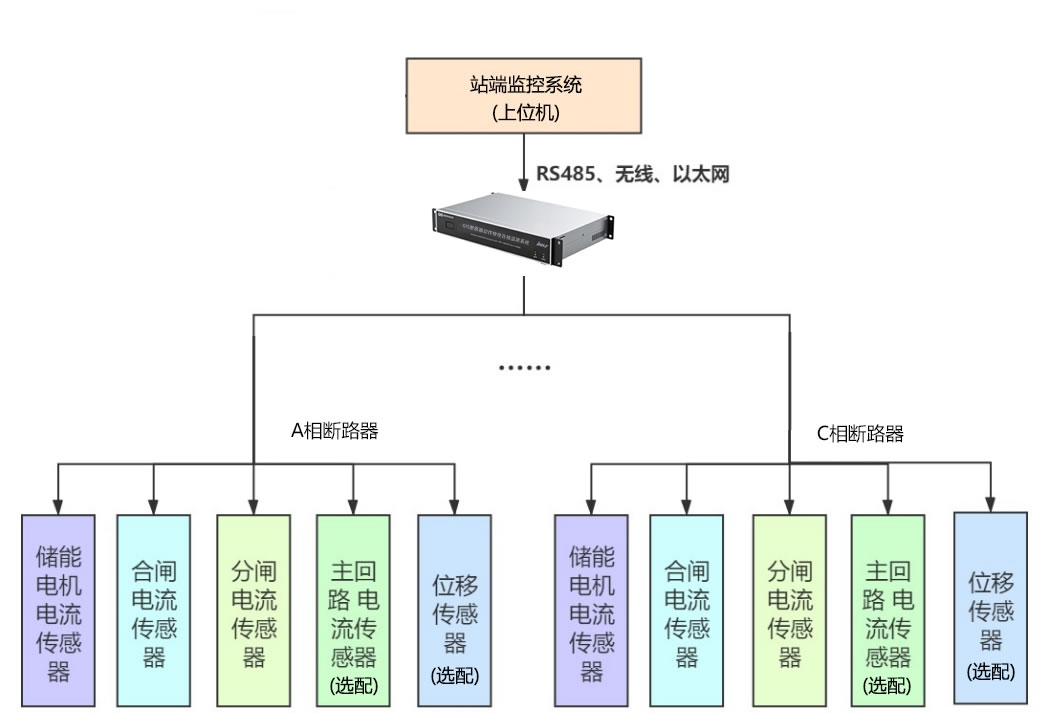
5. जीआईएस मॉनिटरिंग सिस्टम आर्किटेक्चर और घटक
5.1 समग्र सिस्टम आर्किटेक्चर
एक व्यापक जीआईएस स्थिति निगरानी प्रणाली सेंसर नेटवर्क युक्त एक पदानुक्रमित वास्तुकला को नियोजित करता है, बुद्धिमान अधिग्रहण इकाइयाँ, संचार अवसंरचना, और केंद्रीकृत विश्लेषण मंच. वही सेंसर परत विद्युत मापने के लिए पूरे जीआईएस इंस्टॉलेशन में विशेष ट्रांसड्यूसर वितरित करता है, यांत्रिक, रसायन, और थर्मल पैरामीटर. वही किनारा प्रसंस्करण परत बुद्धिमान इलेक्ट्रॉनिक उपकरणों को होस्ट करता है (आईईडी) जो सेंसर सिग्नल को डिजिटाइज़ करता है, स्थानीय विश्लेषण करें, और औद्योगिक प्रोटोकॉल के माध्यम से ऊपर की ओर संचार करें.
वही संचार परत फाइबर ऑप्टिक नेटवर्क लागू करता है, औद्योगिक ईथरनेट स्विच, या वितरित आईईडी से सबस्टेशन ऑटोमेशन सिस्टम और उद्यम निगरानी केंद्रों में डेटा एकत्र करने के लिए वायरलेस टेलीमेट्री. वही अनुप्रयोग परत मानव-मशीन इंटरफ़ेस प्रदान करता है, निदान एल्गोरिदम, अलार्म प्रबंधन, ऐतिहासिक रुझान, और परिसंपत्ति प्रबंधन डेटाबेस के साथ एकीकरण. यह आर्किटेक्चर तत्काल गलती का पता लगाने के लिए वास्तविक समय की निगरानी और पूर्वानुमानित रखरखाव योजना के लिए दीर्घकालिक विश्लेषण दोनों को सक्षम बनाता है.
5.2 सेंसर प्रौद्योगिकी श्रेणियाँ
5.2.1 आंशिक निर्वहन सेंसर
अति उच्च आवृत्ति (यूएचएफ) एंटेना आंशिक निर्वहन घटनाओं के दौरान उत्सर्जित विद्युत चुम्बकीय विकिरण का पता लगाएं. ये सेंसर जीआईएस बाड़ों में स्थापित ढांकता हुआ खिड़कियों या गैस-अछूता समाक्षीय निगरानी बंदरगाहों से जुड़े होते हैं. वही यूएचएफ डिटेक्शन बैंडविड्थ आम तौर पर फैलता है 300 मेगाहर्ट्ज से 3 गीगा, पावर सिस्टम संचालन से कम आवृत्ति वाले विद्युत चुम्बकीय हस्तक्षेप को अस्वीकार करते हुए नैनोसेकंड रेंज में वृद्धि समय के साथ क्षणिक संकेतों को कैप्चर करना.
ध्वनिक उत्सर्जन सेंसर एसएफ6 गैस और जीआईएस संरचनाओं के माध्यम से फैलने वाली पीडी घटनाओं द्वारा उत्पन्न अल्ट्रासोनिक दबाव तरंगों पर प्रतिक्रिया करें. बाहरी आवरण सतहों पर लगे पीजोइलेक्ट्रिक ट्रांसड्यूसर इन यांत्रिक कंपनों का पता लगाते हैं 20-300 kHz आवृत्ति रेंज. वही बहु-सेंसर सरणी दृष्टिकोण सेंसर के बीच आगमन के समय के अंतर को मापकर बसबार रन के साथ या जटिल बे कॉन्फ़िगरेशन के भीतर पीडी स्रोतों का पता लगाने के लिए त्रिकोणीय एल्गोरिदम को सक्षम बनाता है.
5.2.2 तापमान संवेदन उपकरण
फाइबर ऑप्टिक तापमान सेंसर प्रतिदीप्ति क्षय सिद्धांतों का उपयोग विद्युत चुम्बकीय हस्तक्षेप के प्रति प्रतिरक्षा प्रदान करता है, उच्च-वोल्टेज कंडक्टरों से विद्युत अलगाव, और ऊर्जावान घटकों पर सीधे माउंटिंग के लिए उपयुक्तता. वही फ्लोरोसेंट क्रिस्टल सेंसर ऑप्टिकल पल्स द्वारा उत्तेजित होने पर फाइबर टिप में एम्बेडेड प्रकाश उत्सर्जित होता है, क्षय समय तापमान पर निर्भर है. मापन इलेक्ट्रॉनिक्स ±1°C सटीकता के साथ तापमान की गणना करने के लिए इस क्षय विशेषता का विश्लेषण करता है.
वायरलेस बैटरी चालित तापमान ट्रांसमीटर सीधे हाई-वोल्टेज कंडक्टरों पर माउंट करें, स्थानीय तापमान को मापना और ग्राउंडेड बाड़े के माध्यम से रेडियो फ्रीक्वेंसी सिग्नल के माध्यम से डेटा संचारित करना. करंट प्रवाहित करने वाले कंडक्टरों के आसपास के चुंबकीय क्षेत्र से विद्युत संचयन बैटरी प्रतिस्थापन के बिना दशकों तक चलने वाले संचालन को सक्षम बनाता है, जबकि एंटीना युग्मन तकनीकें ग्राउंडेड बाड़े में छोटे एपर्चर के माध्यम से सिग्नल ट्रांसमिशन की अनुमति देती हैं.
5.2.3 SF6 गैस निगरानी उपकरण
ऑनलाइन घनत्व मॉनिटर निरंतर SF6 घनत्व माप प्रदान करने के लिए माइक्रोप्रोसेसर-आधारित गणना के साथ दबाव ट्रांसड्यूसर और तापमान सेंसर शामिल करें. वही घनत्व एल्गोरिथ्म आदर्श गैस मान्यताओं के बजाय राज्य के वास्तविक गैस समीकरण लागू करता है, व्यापक तापमान रेंज में ±1% के भीतर सटीकता प्राप्त करना. एकीकृत डेटा लॉगिंग घनत्व प्रवृत्तियों को पकड़ती है, रिसाव दर की गणना, और अलार्म इवेंट टाइम-स्टैम्प.
गैस गुणवत्ता विश्लेषक SF6 शुद्धता और संदूषण का आकलन करने के लिए कई सेंसिंग प्रौद्योगिकियों को नियोजित करें. ऑक्सीजन सेंसर गैल्वेनिक सेल या ज़िरकोनियम ऑक्साइड प्रौद्योगिकियों का उपयोग करके वायु प्रवेश का पता लगाया जाता है. नमी सेंसर कैपेसिटेंस या एल्यूमीनियम ऑक्साइड प्रतिबाधा माप के आधार पर जल वाष्प एकाग्रता को ट्रैक करें. Decomposition product sensors utilize electrochemical cells or infrared absorption spectroscopy to quantify SOF2, SO2F2, and other breakdown byproducts at parts-per-million sensitivity.
5.2.4 Mechanical Characteristic Sensors
रैखिक विस्थापन ट्रांसड्यूसर employing magnetostrictive or optical encoding principles measure circuit breaker contact travel with sub-millimeter resolution. वही travel-time recorder captures complete stroke profiles during opening and closing operations, enabling calculation of average velocity, maximum velocity, contact acceleration, and stroke consistency between phases.
Vibration accelerometers mounted on operating mechanisms detect mechanical signatures associated with specific mechanism components. Frequency spectrum analysis identifies characteristic frequencies of gear meshing, pawl engagement, buffer impacts, and bearing resonances. Changes in vibration patterns स्नेहन टूटना जैसे यांत्रिक दोष विकसित होने का संकेत मिलता है, वसंत की थकान, या इन स्थितियों के परिचालन संबंधी विफलताओं का कारण बनने से बहुत पहले ही लिंकेज खराब हो जाता है.
5.3 डेटा अधिग्रहण और प्रसंस्करण अवसंरचना
बुद्धिमान इलेक्ट्रॉनिक उपकरण (आईईडी) जीआईएस निगरानी प्रणालियों में एज कंप्यूटिंग नोड्स के रूप में कार्य करें. प्रत्येक IED कई सेंसरों के साथ इंटरफेस करता है, एनालॉग-टू-डिजिटल रूपांतरण प्रदान करना, डिजिटल सिग्नल प्रोसेसिंग, दहलीज तुलना, और घटना रिकॉर्डिंग. वही आईईडी प्रोसेसर स्थानीय स्तर पर डायग्नोस्टिक एल्गोरिदम निष्पादित करता है, निरंतर कच्चे सेंसर डेटा स्ट्रीम के बजाय केवल संसाधित नैदानिक परिणामों और अलार्म सूचनाओं को प्रसारित करके संचार बैंडविड्थ आवश्यकताओं को कम करना.
हाई-स्पीड डेटा अधिग्रहण मॉड्यूल आंशिक निर्वहन निगरानी के लिए नमूना दरों को नियोजित करें 100 एमएस/एस को 1 जीएस/एस (मेगा-नमूने प्रति सेकंड से गीगा-नमूने प्रति सेकंड तक), पल्स आकार विश्लेषण और चरण-समाधान पैटर्न पहचान के लिए पर्याप्त निष्ठा के साथ यूएचएफ क्षणिक तरंगों को कैप्चर करना. तरंगरूप विश्लेषण एल्गोरिदम पल्स आयाम सहित पैरामीटर निकालें, वृद्धि समय, पुनरावृत्ति दर, और विद्युत आवृत्ति वोल्टेज चक्र से चरण संबंध, पीडी स्रोत वर्गीकरण के लिए पैटर्न डेटाबेस का निर्माण.
5.4 संचार और नेटवर्क वास्तुकला
वही सबस्टेशन संचार नेटवर्क आम तौर पर मॉनिटरिंग आईईडी को सबस्टेशन गेटवे सर्वर से जोड़ने वाली एक निरर्थक फाइबर ऑप्टिक रिंग टोपोलॉजी लागू करता है. स्टेशन-स्तरीय स्विच IEEE के साथ गीगाबिट ईथरनेट कनेक्टिविटी प्रदान करें 1588 परिशुद्धता समय प्रोटोकॉल (पी.टी.पी) वितरित सेंसरों में माइक्रोसेकंड-स्तरीय समय संरेखण सुनिश्चित करने वाला सिंक्रनाइज़ेशन. इस बार सिंक्रनाइज़ेशन सटीक अनुक्रम-घटनाओं की रिकॉर्डिंग और यात्रा तरंग दोष स्थान को सक्षम बनाता है.
प्रोटोकॉल रूपांतरण गेटवे मॉनिटरिंग सिस्टम के मूल प्रोटोकॉल के बीच अनुवाद करें (अक्सर मॉडबस टीसीपी या मालिकाना प्रारूप) और सबस्टेशन स्वचालन मानक IEC 61850, सुरक्षात्मक रिलेइंग के साथ एकीकरण को सक्षम करना, स्काडा सिस्टम, और उपयोगिता उद्यम नेटवर्क. वही संचार सुरक्षा वास्तुकला निगरानी ट्रैफ़िक को सुरक्षा और नियंत्रण नेटवर्क से अलग करने के लिए वीएलएएन लागू करता है, डेटा प्रवाह को नियंत्रित करने के लिए फ़ायरवॉल नियम, और केंद्रीकृत निगरानी केंद्रों तक व्यापक क्षेत्र संचार के लिए एन्क्रिप्टेड सुरंगें.
6. जीआईएस मॉनिटरिंग सिस्टम के मुख्य लाभ
6.1 समय-आधारित से शर्त-आधारित रखरखाव में परिवर्तन
परंपरागत समय-आधारित रखरखाव रणनीतियाँ निश्चित कैलेंडर अंतराल पर जीआईएस निरीक्षण और घटक प्रतिस्थापन शेड्यूल करें (जैसे, 5-वर्ष प्रमुख निरीक्षण, 10-वर्ष ओवरहाल) उपकरण की वास्तविक स्थिति की परवाह किए बिना. इस दृष्टिकोण के परिणामस्वरूप स्वस्थ उपकरणों पर अनावश्यक रखरखाव होता है और निर्धारित हस्तक्षेपों के बीच ख़राब उपकरणों की संभावित विफलताएँ होती हैं. स्थिति-आधारित रखरखाव (सी.बी.एम) निरंतर निगरानी द्वारा सक्षम किया गया कार्य बीते समय के बजाय वास्तविक मापी गई स्थिति के आधार पर रखरखाव क्रियाएं करके इस प्रतिमान को बदल देता है.
वही सीबीएम कार्यान्वयन गिरावट की प्रवृत्तियों पर नज़र रखता है, आधारभूत मूल्यों और सीमा सीमाओं के विरुद्ध वास्तविक समय मापदंडों की तुलना करना. जब निगरानी की स्थितियाँ विकासशील समस्याओं का संकेत देती हैं तो रखरखाव गतिविधियाँ शुरू हो जाती हैं, समय से पहले घटक प्रतिस्थापन से बचने के साथ-साथ विफलताओं को रोकने के लिए रखरखाव समय को अनुकूलित करना. यह दृष्टिकोण उपकरण सेवा जीवन का विस्तार करता है, रखरखाव की लागत कम कर देता है, और अनुमानित गिरावट के बजाय वास्तविक गिरावट को संबोधित करके ग्रिड विश्वसनीयता में सुधार करता है.
6.2 प्रारंभिक दोष चेतावनी क्षमताएँ
प्रगतिशील दोष विकास जीआईएस में आम तौर पर विनाशकारी विफलता से पहले पता लगाने योग्य चरणों का पालन किया जाता है. जैसे-जैसे इन्सुलेशन ख़राब होता है, आंशिक निर्वहन गतिविधि महीनों या वर्षों में धीरे-धीरे बढ़ती है. जैसे-जैसे क्षरण बढ़ता है, संपर्क प्रतिरोध उत्तरोत्तर बढ़ता जाता है. यांत्रिक घिसाव पूर्ण तंत्र विफलता से बहुत पहले परिचालन विशेषताओं में सूक्ष्म परिवर्तन उत्पन्न करता है. ऑनलाइन निगरानी प्रणाली इन प्रारंभिक चेतावनी संकेतों का पता लगाएं, घंटों या मिनटों के बजाय हफ्तों या महीनों में मापी गई रखरखाव विंडो प्रदान करना.
वही शीघ्र पता लगाने का लाभ कम-मांग अवधि के दौरान नियोजित आउटेज शेड्यूलिंग को सक्षम बनाता है, आवश्यक स्पेयर पार्ट्स की खरीद, विशेष रखरखाव दल का जुटाना, और महत्वपूर्ण ग्राहकों को सेवा बनाए रखने के लिए अस्थायी आपूर्ति व्यवस्था की तैयारी. यह अप्रत्याशित विफलताओं के लिए आपातकालीन प्रतिक्रिया के साथ बिल्कुल विपरीत है जिसके लिए तत्काल मजबूर आउटेज की आवश्यकता होती है, often during peak demand periods with limited spare parts availability and inadequate preparation time.
6.3 Equipment Service Life Extension
GIS design life typically ranges from 30 तक 40 years under normal operating conditions with appropriate maintenance. फिर भी, actual service life depends heavily on operating stress levels, पर्यावरणीय स्थितियाँ, and maintenance quality. Monitoring systems extend service life by detecting conditions that accelerate aging (overheating, नमी संदूषण, excessive PD activity) while they remain correctable through minor interventions such as re-torquing connections, gas processing, or localized cleaning.
वही life extension methodology combines continuous condition assessment with targeted remedial actions, preventing minor degradation from progressing to major failures requiring complete component replacement. बड़ी उपकरण आबादी से निगरानी डेटा का सांख्यिकीय विश्लेषण रखरखाव प्रक्रियाओं को परिष्कृत करने में सक्षम बनाता है, डिज़ाइन की कमजोरियों की पहचान के लिए निर्माता की प्रतिक्रिया की आवश्यकता होती है, और सैद्धांतिक विफलता दर के बजाय वास्तविक के आधार पर स्पेयर पार्ट्स सूची का अनुकूलन.
6.4 विद्युत आपूर्ति की विश्वसनीयता में वृद्धि
ग्रिड विश्वसनीयता मेट्रिक्स सिस्टम औसत व्यवधान अवधि सूचकांक सहित (जगह) और सिस्टम औसत व्यवधान आवृत्ति सूचकांक (सुरक्षित) जब उपयोगिताएँ व्यापक जीआईएस निगरानी लागू करती हैं तो मापनीय रूप से सुधार होगा. जबरन कटौती में कमी विकासशील दोषों का शीघ्र पता लगाने और योजनाबद्ध सुधार के परिणाम. विश्वसनीयता में निगरानी प्रणाली का योगदान अस्पतालों जैसे महत्वपूर्ण बुनियादी ढांचे की सेवा देने वाले अनुप्रयोगों में विशेष रूप से महत्वपूर्ण हो जाता है, डेटा केंद्र, आपातकालीन सेवाएं, और बड़े पैमाने पर परिवहन प्रणाली.
परिचालन लचीलापन जैसे-जैसे निगरानी वास्तविक समय उपकरण स्वास्थ्य दृश्यता प्रदान करती है, बढ़ती जाती है, अत्यधिक सुरक्षा मार्जिन के साथ रूढ़िवादी संचालन के बजाय डिजाइन सीमा तक आत्मविश्वासपूर्ण लोडिंग को सक्षम करना. आकस्मिक परिस्थितियों के दौरान (नेटवर्क में अन्यत्र जबरन रुकावटें), निगरानी यह पुष्टि करती है कि अस्थायी अधिभार की स्थिति स्वीकार्य थर्मल और विद्युत तनाव स्तरों के भीतर बनी हुई है, आपात्कालीन स्थिति के दौरान पारेषण क्षमता उपयोग को अधिकतम करना.
6.5 ऐतिहासिक डेटा विश्लेषण और नैदानिक अंतर्दृष्टि
दीर्घकालिक रुझान विश्लेषण मॉनिटरिंग डेटा से स्नैपशॉट माप में अदृश्य गिरावट पैटर्न का पता चलता है. आंशिक निर्वहन परिमाण में धीरे-धीरे वृद्धि होती है, प्रगतिशील नमी संचय, या धीरे-धीरे बढ़ता कनेक्शन तापमान केवल महीनों या वर्षों के ऐतिहासिक डेटा की जांच करने पर ही स्पष्ट हो जाता है. डेटाबेस विश्लेषण उपकरण की स्थिति को परिचालन इतिहास के साथ सहसंबद्ध करें (प्रोफ़ाइल लोड करें, आवृत्ति बदलना, पर्यावरणीय स्थितियाँ) कारण संबंधों की पहचान करना और पूर्वानुमानित मॉडल को परिष्कृत करना.
वही बेड़े-व्यापी विश्लेषण क्षमता किसी उपयोगिता के सेवा क्षेत्र या उपकरण निर्माता के वैश्विक स्थापित आधार पर कई समान जीआईएस इंस्टॉलेशन से डेटा एकत्र करता है. सांख्यिकीय तरीके जांच की आवश्यकता वाले आउटलेर्स की पहचान करते हैं, यथार्थवादी प्रदर्शन मानक स्थापित करें, और डिज़ाइन संशोधनों या रखरखाव प्रक्रिया परिवर्तनों के प्रभाव की मात्रा निर्धारित करें. यह सामूहिक बुद्धिमत्ता व्यक्तिगत साइट विश्लेषण से कहीं अधिक सीखने और निरंतर सुधार को गति देती है.
7. आंशिक डिस्चार्ज डिटेक्शन टेक्नोलॉजीज तुलना
| डिटेक्शन टेक्नोलॉजी | परिचालन सिद्धांत | संवेदनशीलता स्तर | स्थानीयकरण क्षमता | शोर प्रतिरक्षण | विशिष्ट अनुप्रयोग |
|---|---|---|---|---|---|
| अति-उच्च आवृत्ति (यूएचएफ) | विद्युत चुम्बकीय विकिरण का पता लगाता है (300 मेगाहर्टज – 3 गीगा) जीआईएस बाड़ों से जुड़े एंटेना का उपयोग करके पीडी घटनाओं के दौरान उत्सर्जित | उत्कृष्ट: पीडी का पता लगाता है <5 अनुकूल परिस्थितियों में पी.सी; विशिष्ट दहलीज 10-20 पीसी | बहुत अच्छा: कई सेंसरों के साथ उड़ान के समय का त्रिकोणासन ±1-2 मीटर के भीतर स्रोतों का पता लगाता है | उत्कृष्ट: उच्च-आवृत्ति ऑपरेशन बिजली आवृत्ति हस्तक्षेप और रेडियो प्रसारण को अस्वीकार करता है | जीआईएस के लिए प्राथमिक विधि; ऑनलाइन सतत निगरानी के लिए उपयुक्त; विद्युत शोर वाले वातावरण में प्रभावी |
| ध्वनिक उत्सर्जन (ऐ) | अल्ट्रासोनिक दबाव तरंगों का पता लगाता है (20-300 kHz) बाहरी सतहों पर पीज़ोइलेक्ट्रिक सेंसर का उपयोग करके पीडी घटनाओं द्वारा उत्पन्न | अच्छा: मध्यम से गंभीर पीडी का पता लगाता है (आम तौर पर >50 पीसी); स्रोत से दूरी के साथ संवेदनशीलता कम हो जाती है | अच्छा: सेंसर सरणियों के साथ त्रिकोणासन संभव; जीआईएस संरचना जटिलता के आधार पर सटीकता ±5-10 मीटर | मध्यम: यांत्रिक कंपन के प्रति संवेदनशील, पंप शोर, ट्रांसफार्मर गुंजन; डिजिटल फ़िल्टरिंग आवश्यक है | यूएचएफ का पूरक; ज्ञात दोषों को स्थानीयकृत करने के लिए प्रभावी; कमीशनिंग निरीक्षण के दौरान उपयोगी |
| क्षणिक पृथ्वी वोल्टेज (टीईवी) | आंतरिक पीडी घटनाओं से कैपेसिटिव कपलिंग के कारण बाहरी जीआईएस संलग्नक सतहों पर वोल्टेज पल्स को मापता है | मध्यम: महत्वपूर्ण पीडी गतिविधि का पता लगाता है (आम तौर पर >100 पीसी); संवेदनशीलता बाड़े की ज्यामिति के साथ बदलती रहती है | सीमित: इंगित करता है कि किस संलग्नक अनुभाग में पीडी है; सटीक स्थान के लिए हैंडहेल्ड सेंसर के साथ पैदल सर्वेक्षण की आवश्यकता होती है | मध्यम: बाहरी विद्युत चुम्बकीय हस्तक्षेप के प्रति संवेदनशील; परिरक्षण और फ़िल्टरिंग से प्रदर्शन में सुधार होता है | आवधिक निरीक्षण के लिए पोर्टेबल सर्वेक्षण उपकरण; विस्तृत जांच की आवश्यकता वाले समस्याग्रस्त क्षेत्रों की पहचान करने के लिए त्वरित स्क्रीनिंग |
| रासायनिक जांच (गैस विश्लेषण) | SF6 अपघटन उत्पादों का विश्लेषण करता है (SOF2, SO2F2, आदि।) गैस क्रोमैटोग्राफी या इलेक्ट्रोकेमिकल सेंसर का उपयोग करना | रासायनिक उपोत्पादों के लिए उत्कृष्ट: पीपीएम-स्तर के अपघटन उत्पादों का पता लगाता है जो निरंतर निर्वहन गतिविधि का संकेत देता है | गरीब: गैस के नमूने पूरे सीलबंद डिब्बे का प्रतिनिधित्व करते हैं; डिब्बे के भीतर डिस्चार्ज स्थान का पता नहीं लगाया जा सकता | उत्कृष्ट: विद्युत शोर से प्रतिरक्षित; रासायनिक विश्लेषण डिस्चार्ज या थर्मल दोष का निश्चित प्रमाण प्रदान करता है | रखरखाव रुकावटों के दौरान आवधिक नमूनाकरण; महत्वपूर्ण स्थापनाओं के लिए ऑनलाइन सेंसर; विद्युत पीडी पहचान निष्कर्षों की पुष्टि करता है |
| उच्च आवृत्ति धारा ट्रांसफार्मर (एचएफसीटी) | रोगोस्की कॉइल्स या करंट ट्रांसफार्मर का उपयोग करके जीआईएस ग्राउंडिंग कंडक्टरों में उच्च आवृत्ति वाले करंट पल्स को मापता है | मध्यम से अच्छा: पीडी का पता लगाता है >20-50 सेंसर की स्थिति और ग्राउंडिंग कॉन्फ़िगरेशन के आधार पर पीसी | सीमित: पहचानता है कि कौन सा ग्राउंडिंग कंडक्टर पीडी सिग्नल ले जाता है; एकाधिक सेंसर ज़ोन पहचान में सुधार करते हैं | अच्छा: बैंडपास फ़िल्टरिंग (3-30 मेगाहर्ट्ज ठेठ) बिजली आवृत्ति और कई हस्तक्षेप स्रोतों को अस्वीकार करता है | रेट्रोफिट अनुप्रयोग जहां यूएचएफ सेंसर के लिए संलग्नक प्रवेश अव्यावहारिक है; ग्राउंडिंग सर्किट अखंडता की निगरानी करता है |
7.1 अति-उच्च आवृत्ति (यूएचएफ) पता लगाने की विधि
7.1.1 यूएचएफ ऑपरेटिंग सिद्धांत और सिग्नल विशेषताएँ
यूएचएफ आंशिक निर्वहन का पता लगाना इस तथ्य का फायदा उठाता है कि पीडी घटनाओं के दौरान तेजी से चार्ज आंदोलन यूएचएफ स्पेक्ट्रम में विस्तारित आवृत्ति सामग्री के साथ विद्युत चुम्बकीय विकिरण उत्पन्न करता है (300 मेगाहर्ट्ज से 3 गीगा). वही पीडी वर्तमान पल्स इसका उदय समय बहुत तेज है (आम तौर पर <1 नैनोसेकंड), ब्रॉडबैंड विद्युत चुम्बकीय स्पेक्ट्रम का उत्पादन. जीआईएस धातु बाड़े वेवगाइड के रूप में कार्य करते हैं, कम आवृत्तियों की तुलना में अपेक्षाकृत कम क्षीणन के साथ संरचना के साथ इन यूएचएफ संकेतों का प्रसार.
वही यूएचएफ सेंसर जीआईएस बाड़े में एक ढांकता हुआ खिड़की या विशेष निगरानी पोर्ट के माध्यम से एसएफ 6 गैस स्थान से जुड़ा एक एंटीना तत्व होता है. वाणिज्यिक सेंसर डिज़ाइन में मानक जीआईएस व्यूइंग पोर्ट के माध्यम से स्थापित आंतरिक डिस्क एंटेना शामिल हैं, बाहरी पैच एंटेना ढांकता हुआ स्पेसर के माध्यम से युग्मित होते हैं, और इंसुलेटर सपोर्ट में निर्मित एकीकृत सेंसर. वही सिग्नल प्रोसेसिंग श्रृंखला प्राप्त यूएचएफ सिग्नल को बढ़ाता है, सिग्नल-टू-शोर अनुपात को अनुकूलित करने के लिए बैंडपास फ़िल्टरिंग लागू करता है, और बाद के विश्लेषण के लिए तरंगों को डिजिटाइज़ करता है.
7.1.2 यूएचएफ सेंसर प्रकार और स्थापना के तरीके
आंतरिक यूएचएफ सेंसर पीडी स्रोतों को इष्टतम युग्मन प्रदान करें क्योंकि एंटीना एसएफ 6 गैस वातावरण में रहता है जहां डिस्चार्ज घटनाएं होती हैं. स्थापना के लिए मौजूदा निरीक्षण बंदरगाहों या कस्टम-डिज़ाइन की गई निगरानी खिड़कियों के माध्यम से जीआईएस डिब्बों तक पहुंच की आवश्यकता होती है. वही ढांकता हुआ खिड़की सामग्री (आम तौर पर एपॉक्सी या फाइबरग्लास डाला जाता है) दबाव नियंत्रण और इन्सुलेशन अखंडता को बनाए रखते हुए विद्युत चुम्बकीय तरंग संचरण की अनुमति देता है.
बाहरी यूएचएफ सेंसर जीआईएस बाड़ों के बाहर माउंट करें, छोटे छिद्रों के माध्यम से प्रवेश करने वाले विद्युत चुम्बकीय क्षेत्रों का पता लगाना, इन्सुलेटर इंटरफ़ेस, या सीधे पतले बाड़े अनुभागों के माध्यम से. यह इंस्टॉलेशन विधि रेट्रोफिट अनुप्रयोगों के लिए उपयुक्त है जहां आंतरिक पहुंच अनुपलब्ध है या जहां सेंसर इंस्टॉलेशन के दौरान गैस डिब्बे की अखंडता को बनाए रखना महत्वपूर्ण है. युग्मन दक्षता बाहरी सेंसर के लिए आंतरिक माउंटिंग की तुलना में कम है लेकिन महत्वपूर्ण पीडी गतिविधि का पता लगाने के लिए पर्याप्त है, विशेष रूप से जब एकाधिक सेंसर स्थानिक विविधता प्रदान करते हैं.
7.2 ध्वनिक उत्सर्जन जांच पद्धति
ध्वनिक पीडी का पता लगाना जब विद्युत निर्वहन की घटनाएं तेजी से स्थानीय गैस दबाव परिवर्तन पैदा करती हैं तो उत्पन्न अल्ट्रासोनिक दबाव तरंगों का पता लगाने के लिए पीजोइलेक्ट्रिक सेंसर पर निर्भर करता है. वही ध्वनिक तरंग प्रसार एसएफ6 गैस और जीआईएस के माध्यम से यांत्रिक संरचनाएं प्रतिबिंबों के साथ जटिल पथों का अनुसरण करती हैं, मोड रूपांतरण, और क्षीणन जो आवृत्ति और दूरी के साथ बदलता रहता है.
सेंसर स्थापना typically employs magnetic mounting bases attached to external GIS enclosure surfaces. Acoustic coupling medium (gel or grease) ensures efficient sound transmission from the metal surface to the piezoelectric crystal. Multi-sensor arrays distributed along GIS bays enable triangulation algorithms that calculate PD source locations by analyzing arrival time differences. Modern acoustic systems employ at least 4-6 sensors per bay to achieve reliable 3D localization even with the complex acoustic environment inside GIS structures.
7.3 क्षणिक पृथ्वी वोल्टेज (टीईवी) Technique
TEV detection measures voltage pulses appearing on the external surface of grounded GIS enclosures due to capacitive coupling from internal partial discharge events. Each PD pulse induces a transient voltage between the enclosure surface and true earth ground, आमतौर पर डिस्चार्ज परिमाण और माप स्थान के आधार पर मिलीवोल्ट से वोल्ट की सीमा में.
वही टीईवी सेंसर एक कैपेसिटिव कपलिंग इलेक्ट्रोड शामिल है, उच्च-इनपुट प्रतिबाधा एम्पलीफायर, और बैंडपास फ़िल्टर को विशिष्ट TEV आवृत्ति रेंज के लिए अनुकूलित किया गया है 3-100 मेगाहर्टज. पोर्टेबल टीईवी उपकरण वॉक-थ्रू सर्वेक्षण सक्षम करें जहां ऑपरेटर व्यवस्थित रूप से सेंसर जांच को जीआईएस संलग्नक सतहों पर छूते हैं, ऊंचे टीईवी सिग्नल स्तर वाले स्थानों को नोट करना. इन “गर्म स्थान” पीडी स्रोत का सटीक पता लगाने के लिए यूएचएफ या ध्वनिक सेंसर के साथ अधिक विस्तृत जांच की आवश्यकता वाले डिब्बों की पहचान करें.
7.4 रासायनिक जांच विधि (गैस अपघटन विश्लेषण)
SF6 गैस अपघटन विश्लेषण आंशिक निर्वहन या थर्मल दोष गतिविधि का रासायनिक साक्ष्य प्रदान करता है. वही विघटन तंत्र इसमें उच्च-ऊर्जा डिस्चार्ज चैनल में SF6 अणु का टूटना शामिल है, प्रतिक्रियाशील फ्लोरीन रेडिकल्स बनाते हैं जो स्थिर उपोत्पादों में पुनः संयोजित होते हैं. प्रमुख अपघटन उत्पादों में सल्फर टेट्राफ्लोराइड शामिल है (SF4), थियोनिल फ्लोराइड (SOF2), सल्फ्यूरिल फ्लोराइड (SO2F2), और अंततः सल्फर डाइऑक्साइड (SO2) और हाइड्रोफ्लोरोइक एसिड (एचएफ) जब नमी मौजूद हो.
गैस नमूनाकरण प्रक्रियाएँ गैस वाल्व से जुड़े नमूना सिलेंडरों का उपयोग करके सीलबंद जीआईएस डिब्बों से एसएफ 6 नमूने निकालें. प्रयोगशाला विश्लेषण में तापीय चालकता या मास स्पेक्ट्रोमीटर डिटेक्टरों के साथ गैस क्रोमैटोग्राफी का उपयोग किया जाता है, प्रति मिलियन भागों की सीमा में पता लगाने की सीमा प्राप्त करना. ऑनलाइन गैस मॉनिटर महत्वपूर्ण जीआईएस प्रतिष्ठानों के लिए लघु गैस क्रोमैटोग्राफ या इलेक्ट्रोकेमिकल सेंसर सरणी शामिल हैं जो प्रोग्राम किए गए अंतराल पर स्वचालित विश्लेषण करते हैं (आम तौर पर दैनिक या साप्ताहिक), विकासशील दोषों का पता लगाने के लिए समय के साथ ट्रेंडिंग अपघटन उत्पाद सांद्रता.
8. SF6 गैस मॉनिटरिंग टेक्नोलॉजीज
8.1 SF6 गैस घनत्व और दबाव की निगरानी
8.1.1 Density Relay vs Online Monitoring System Comparison
| Comparison Aspect | Traditional Density Relay | Online Density Monitoring System |
|---|---|---|
| परिचालन सिद्धांत | Bimetallic temperature compensation with mechanical contacts; measures pressure and corrects for temperature using thermal expansion properties | Electronic pressure sensor with RTD temperature sensor; microprocessor calculates density using real gas equations; digital output via communication protocol |
| माप सटीकता | ±2-3% of full scale; affected by mechanical hysteresis and aging; calibration drift over time reduces accuracy | ±0.5-1% of reading; digital calibration eliminates mechanical drift; self-diagnostic functions verify sensor health |
| Temperature Compensation Range | Limited to design range (typically -25°C to +55°C); accuracy degrades outside this range; single compensation curve may not suit all climates | विस्तृत श्रृंखला (-50°C से +70°C सामान्य); गणितीय क्षतिपूर्ति किसी भी तापमान के अनुकूल होती है; उच्च ऊंचाई वाले स्थलों के लिए ऊंचाई मुआवजा उपलब्ध है |
| अलार्म कार्यक्षमता | निश्चित घनत्व सीमा पर पृथक अलार्म संपर्क (आम तौर पर एक अलार्म, एक तालाबंदी); प्रतिस्थापन के बिना थ्रेसहोल्ड फ़ील्ड-समायोज्य नहीं हैं | एकाधिक प्रोग्रामयोग्य अलार्म स्तर; रिसाव दर गणना के आधार पर ट्रेंडिंग अलार्म; संचार इंटरफ़ेस के माध्यम से दूरस्थ सीमा समायोजन |
| डेटा लॉगिंग और ट्रेंडिंग | कोई नहीं – केवल तात्कालिक संपर्क स्थिति प्रदान करता है; ऐतिहासिक रुझानों को निरीक्षण के दौरान मैन्युअल रिकॉर्डिंग की आवश्यकता होती है | टाइमस्टैम्प्ड दबाव के साथ व्यापक डेटा लॉगिंग, तापमान, परिकलित घनत्व; रिसाव दर का चलन; अलार्म के लिए इवेंट रिकॉर्डिंग |
| रिमोट मॉनिटरिंग एकीकरण | संपर्क स्थिति केवल आरटीयू या रिले पैनलों के हार्ड-वायर्ड कनेक्शन के माध्यम से; दूर-दूर तक कोई निदानात्मक जानकारी उपलब्ध नहीं है | मोडबस के माध्यम से पूर्ण एकीकरण, आईईसी 61850, या अन्य प्रोटोकॉल; मापा मान प्रदान करता है, निदान स्थिति, SCADA और निगरानी प्रणालियों के लिए अंशांकन डेटा |
| रखरखाव आवश्यकताएँ | प्रत्येक को आवधिक पुन: अंशांकन की अनुशंसा की जाती है 5-10 साल; यांत्रिक घिसाव विश्वसनीयता को प्रभावित करता है; संपर्क ऑक्सीकरण झूठे अलार्म का कारण बन सकता है | स्व-अंशांकन इलेक्ट्रॉनिक्स को न्यूनतम रखरखाव की आवश्यकता होती है; पुन: अंशांकन की आवश्यकता होने पर सेंसर ड्रिफ्ट मॉनिटरिंग अलर्ट; कोई यांत्रिक घिसाव घटक नहीं |
| रिसाव का पता लगाने की क्षमता | केवल व्यापक लीक का पता लगाता है जिससे घनत्व अलार्म सीमा से नीचे गिर जाता है; कोई रिसाव दर की जानकारी नहीं देता; निरीक्षणों के बीच धीमी गति से लीक का पता नहीं चल पाता है | घनत्व प्रवृत्ति विश्लेषण से प्रति घंटा/दैनिक रिसाव दरों की गणना करता है; धीमी लीक का पता लगाता है (0.1% प्रति वर्ष) दिनों के भीतर; अलार्म सीमा तक समय की भविष्यवाणी करता है |
| स्थापना लचीलापन | जीआईएस डिब्बे में सीधे स्थापित करना आवश्यक है; दूरस्थ संकेत के लिए सीमित विकल्प; लंबे केशिका कनेक्शन सटीकता को कम करते हैं | सेंसर सीधे डिब्बे पर लगाए जा सकते हैं या छोटी केशिका के माध्यम से जुड़ सकते हैं; इलेक्ट्रॉनिक सिग्नल बिना किसी गिरावट के लंबी दूरी तक संचारित होते हैं |
| लागत संबंधी विचार | प्रारंभिक उपकरण लागत कम; रखरखाव की जरूरतों और सीमित नैदानिक क्षमता के कारण रूढ़िवादी गैस टॉप-अप प्रथाओं के कारण उच्च जीवनचक्र लागत | उच्चतर प्रारंभिक निवेश; कम रखरखाव के माध्यम से कम जीवनचक्र लागत, अनुकूलित गैस प्रबंधन, और अनिर्धारित लीक से उपकरण विफलताओं की रोकथाम |
8.1.2 तापमान क्षतिपूर्ति तकनीक
तापमान क्षतिपूर्ति की आवश्यकता SF6 गैस घनत्व के कारण उत्पन्न होता है (द्रव्यमान प्रति इकाई आयतन) तापमान में परिवर्तन होने पर स्थिर रहता है, लेकिन दबाव काफी भिन्न होता है. निरंतर द्रव्यमान पर, एक SF6 डिब्बे में दबाव में लगभग परिवर्तन का अनुभव होता है 0.3-0.5% प्रति डिग्री सेल्सियस. तापमान क्षतिपूर्ति के बिना, 30°C तापमान में उतार-चढ़ाव का कारण होगा 9-15% pressure variation despite unchanged gas quantity.
आधुनिक ऑनलाइन निगरानी प्रणाली employ digital compensation algorithms implementing the real gas equation of state rather than simplified ideal gas law. The algorithm accounts for SF6’s compressibility factor variation with temperature and pressure, achieving density calculation accuracy within ±0.5% across the full operating temperature range. Multiple temperature sensors at different locations on large compartments detect temperature gradients, using averaged values to improve calculation accuracy.
8.2 SF6 Gas Leakage Detection Systems
8.2.1 Infrared SF6 Detection Technology
Infrared SF6 leak detectors exploit the gas’s strong infrared absorption at specific wavelengths, particularly around 10.6 micrometers. Portable infrared detectors employ a pump to draw air samples across an infrared source and detector, measuring absorption to quantify SF6 concentration. These instruments achieve sensitivity levels of 1-10 प्रति मिलियन भाग (पीपीएम), suitable for locating leak sources during manual surveys of GIS installations.
Fixed infrared monitors installed in GIS rooms provide continuous ambient SF6 concentration monitoring. वही detection principle uses non-dispersive infrared (एनडीआईआर) technology with reference and measurement cells to compensate for light source aging and optical window contamination. Typical alarm thresholds include 500 ppm for ventilation activation and 1000 ppm for personnel evacuation, well below the asphyxiation risk level but indicating significant leakage requiring investigation.
8.2.2 Laser-Based SF6 Detection Methods
Tunable diode laser absorption spectroscopy (टीडीएलएएस) represents the most sensitive SF6 detection technology, achieving parts-per-billion sensitivity in laboratory conditions and sub-ppm sensitivity in field applications. वही TDLAS system employs a semiconductor laser tuned to a specific SF6 absorption line, measuring absorption along an open optical path to detect SF6 plumes emanating from leak sources.
Laser scanning applications include both handheld devices for leak survey work and fixed installations providing perimeter monitoring of GIS rooms or outdoor GIS installations. वही open-path configuration eliminates sampling pumps and consumable filters, enabling very long service intervals. Advanced systems incorporate GPS and imaging capabilities to create visual maps showing leak locations overlaid on facility drawings or photographs.
8.3 SF6 Gas Purity Monitoring
SF6 purity specifications for new gas typically require ≥99.9% SF6 by volume, with strict limits on air (<0.05%), सीएफ4 (<0.05%), नमी (<15 पीपीएमवी), and mineral oil (<1 mg/L). Gas purity degradation occurs through seal leakage admitting air, contamination during maintenance when compartments are opened, or chemical reactions with materials inside the GIS.
Online purity monitoring employs multiple sensor technologies. ऑक्सीजन सेंसर गैल्वेनिक सेल या ज़िरकोनियम ऑक्साइड प्रौद्योगिकियों का उपयोग करके वायु प्रवेश का पता लगाया जाता है, which simultaneously indicates compromised pressure containment. Dielectric strength monitors measure the voltage withstand capability of gas samples, providing a functional assessment of insulation performance that integrates the effects of all contamination types. Significant purity reduction triggers gas processing procedures including evacuation, छनन, and re-filling with fresh SF6 to restore specifications.
8.4 SF6 Gas Moisture Content Monitoring
Moisture contamination in SF6 gas creates multiple problems: reduced dielectric strength when water vapor condenses on cold insulator surfaces, accelerated insulator degradation through surface tracking, and corrosive byproduct formation when moisture reacts with SF6 decomposition products to generate hydrofluoric acid (एचएफ).
Online moisture monitors commonly use aluminum oxide sensor technology. वही sensor element comprises a thin porous aluminum oxide layer deposited on a conductive substrate, with a gold electrode coating. Water molecules adsorb into the aluminum oxide pores, changing the electrical capacitance or resistance in proportion to moisture content. These sensors provide continuous measurement from <10 ppmv to >1000 ppmv moisture concentration, with alarm thresholds typically set at 150-200 ppmv to prevent condensation under worst-case low temperature conditions.
8.5 SF6 Decomposition Product Monitoring
8.5.1 Key Decomposition Products and Their Significance
Sulfur tetrafluoride (SF4) forms as the primary decomposition product during partial discharge and arcing events. SF4 rapidly hydrolyzes in the presence of moisture, producing SOF2 and HF. Thionyl fluoride (SOF2) और सल्फ्यूरिल फ्लोराइड (SO2F2) represent the major stable decomposition products detectable in used SF6 gas. Concentrations above 10-20 ppm indicate sustained discharge activity or a recent high-energy fault.
Sulfur dioxide (SO2) forms through further decomposition of sulfur fluoride compounds, particularly in the presence of moisture and solid materials. Hydrofluoric acid (एचएफ) results from the reaction between fluorine compounds and water, creating a highly corrosive substance that attacks glass insulators, aluminum enclosures, and organic materials. Detection of SO2 or HF indicates severe conditions requiring immediate investigation and likely compartment gas replacement.
8.5.2 Gas Chromatography Analysis Methods
गैस क्रोमैटोग्राफी (जीसी) provides the reference method for quantitative analysis of SF6 decomposition products. वही GC procedure involves injecting a gas sample into a chromatographic column where different molecular species separate based on their interaction with the column packing material. A thermal conductivity detector (टीसीडी) or electron capture detector (ECD) quantifies each component as it elutes from the column.
Online gas chromatograph systems for continuous GIS monitoring incorporate automated sampling valves, miniaturized columns, and digital signal processing. Analysis cycles typically run every 1-24 hours depending on criticality, with results automatically logged and compared against trending thresholds. The system generates alarms when decomposition product concentrations exceed baseline levels or when rate of increase suggests accelerating fault development.
9. तापमान निगरानी प्रौद्योगिकी अनुप्रयोग

| प्रौद्योगिकी प्रकार | फ्लोरोसेंट फाइबर ऑप्टिक | वायरलेस तापमान सेंसर | इन्फ्रारेड थर्मोग्राफी | वितरित फाइबर ऑप्टिक (डीटीएस) |
|---|---|---|---|---|
| माप सिद्धांत | Temperature-dependent fluorescent decay time of crystal sensor at fiber tip; optical signal immune to EMI | Battery-powered transmitter mounted on HV conductor; RF signal transmission through enclosure; energy harvesting from magnetic field | थर्मल विकिरण का पता लगाना (8-14 μm wavelength) using infrared camera; गैर-संपर्क माप | Raman scattering in optical fiber; continuous temperature profile along entire fiber length |
| विशिष्ट सटीकता | ±1°C पूर्ण सटीकता; ±0.1°C repeatability; stable long-term calibration | ±2-3°C सामान्य; affected by ambient temperature compensation and calibration drift over years | ±2-5°C depending on emissivity assumptions, दूरी, and atmospheric absorption; requires surface emissivity knowledge | ±1-2°C spatial averaged temperature; accuracy improves with averaging length but sacrifices spatial resolution |
| प्रतिक्रिया समय | 1-10 seconds depending on sensor thermal mass; suitable for real-time monitoring of dynamic processes | 10-60 सेकंड सामान्य; limited by RF transmission update rate and sensor thermal time constant | Instantaneous image capture; real-time video possible at 30-60 Hz frame rates for dynamic fault detection | Minutes to tens of minutes for complete fiber scan depending on fiber length and required spatial resolution |
| स्थानिक कवरेज | Point measurement at specific location; multiple fiber runs required for comprehensive coverage; 1-8 sensors per bay typical | Point measurement on HV conductor; strategic placement at connections, फिसलते संपर्क; 3-6 प्रति बे सेंसर | 2D thermal imaging of visible surfaces; requires line-of-sight access; inspection windows needed for internal GIS | Continuous measurement along fiber; 1-5 meter spatial resolution over kilometers of fiber length |
| स्थापना जटिलता | मध्यम: requires fiber routing from sensor to signal conditioner; sensors attach directly to HV components during GIS assembly or outages | सरल: wireless sensors self-contained; installation during assembly or live-line using hot-stick tools; no external connections | Simple for external surveys; complex for permanent internal installation requiring transparent windows maintaining pressure and insulation | जटिल: fiber routing throughout GIS structure; termination and connection to interrogator unit; fiber mechanical protection |
| रखरखाव आवश्यकताएँ | न्यूनतम: no batteries or wearing parts; optical fibers very reliable; signal conditioner calibration every 2-5 साल | बैटरी प्रतिस्थापन प्रत्येक 5-15 years depending on power harvesting efficiency and transmission frequency; antenna inspection | Camera calibration annually; lens cleaning; सॉफ़्टवेयर अद्यतन; periodic verification with blackbody reference source | न्यूनतम: passive fiber has no wearing parts; interrogator laser and detector calibration every 1-2 साल |
| Cost per Measurement Point | मध्यम से उच्च: sensor cost $200-800 प्रत्येक; signal conditioner $2000-5000 handles multiple sensors (आम तौर पर 4-8 चैनल) | मध्यम: sensor cost $150-400 प्रत्येक; receiver/gateway $1000-3000; no per-sensor signal conditioning cost | High for permanent systems: थर्मल कैमरे $5000-50,000; lower for periodic manual surveys using portable cameras | उच्च प्रारंभिक लागत ($15,000-50,000+ प्रश्नकर्ता); low incremental cost for additional fiber length; economical for many points |
| आदर्श अनुप्रयोग | Critical connection monitoring; sliding contact temperature; circuit breaker mechanism overheating; transformer tap changer contacts | बसबार कनेक्शन; आइसोलेटर संपर्क; केबल समाप्ति; retrofit applications avoiding fiber installation complexity | Periodic inspections during commissioning or troubleshooting; switchgear thermal surveys; external enclosure hotspot detection | लंबी बसबार चलती है; cable galleries; सुरंग स्थापना; applications requiring spatial temperature gradients and hotspot location |
| डेटा एकीकरण | Direct digital output via Modbus, प्रोफिबस, or analog 4-20mA; easy SCADA integration; timestamped data logging | Wireless gateway provides Modbus TCP or similar protocol; cloud connectivity options; some models offer direct IEC 61850 | Software generates reports; thermal images; प्रवृत्ति विश्लेषण; integration requires manual data transfer unless automated system deployed | Interrogator provides temperature vs. distance profile via Ethernet; software integrates with monitoring platforms; अलार्म पीढ़ी |
9.1 फ्लोरोसेंट फाइबर ऑप्टिक तापमान सेंसर

फ्लोरोसेंट फाइबर ऑप्टिक सेंसर (खाई) employ rare-earth doped crystal sensor elements at the tip of a glass optical fiber. When excited by a pulse of blue or green LED light transmitted down the fiber, the crystal emits fluorescent light with an exponential decay time that depends solely on temperature. वही माप प्रणाली analyzes this decay characteristic with high precision, calculating temperature independent of fiber length, bending losses, कनेक्टर का ख़राब होना, या प्रकाश स्रोत की तीव्रता में भिन्नता.
वही intrinsic safety characteristics of FFOS make this technology ideal for high-voltage applications. The fiber contains no metallic elements, eliminating potential discharge inception points. The dielectric nature allows routing fibers directly on energized conductors without creating parallel capacitance or ground paths. ईएमआई प्रतिरक्षा ensures measurement accuracy even in the severe electromagnetic environment during GIS switching operations or nearby fault current flow.
9.2 Wireless Temperature Sensor Technology
वायरलेस तापमान ट्रांसमीटर for GIS applications incorporate surface acoustic wave (देखा) or digital radio frequency identification (RFID) technologies to enable battery-free operation. वही SAW sensor uses a piezoelectric crystal whose resonant frequency shifts with temperature. External antenna interrogation provides both measurement power and data retrieval via inductive coupling through the grounded GIS enclosure.
बैटरी चालित वायरलेस सेंसर offer greater communication range and faster update rates than passive SAW devices, at the cost of limited operational life. Modern designs incorporate energy harvesting from the magnetic field surrounding current-carrying conductors, capturing milliwatts of power sufficient to extend battery life to 10-15 years even with frequent transmission intervals. वही wireless protocol typically operates at license-free ISM band frequencies (915 MHz or 2.4 गीगा), with communication protocols optimized for low power consumption and electromagnetic compatibility.
9.3 Infrared Thermography Applications
Infrared thermographic inspection of GIS installations detects external enclosure temperature patterns that may indicate internal hotspots from loose connections or contact deterioration. वही thermal camera captures two-dimensional temperature distributions across viewed surfaces, with modern instruments providing radiometric temperature measurement at each pixel in a 320×240 or 640×480 array.
वही inspection methodology requires consideration of surface emissivity—the efficiency with which materials radiate thermal energy. Painted surfaces have high emissivity (0.85-0.95) and accurately represent true temperature, while polished metal surfaces have low emissivity (0.05-0.15) and appear cooler than actual temperature. Quantitative thermal analysis corrects for emissivity, reflected background temperature, वायुमंडलीय अवशोषण, and distance to determine true surface temperatures. Periodic surveys establish baseline thermal patterns, with subsequent comparisons identifying areas of temperature increase indicating developing faults.
9.4 वितरित तापमान संवेदन (डीटीएस) प्रणाली
वितरित तापमान संवेदन technology uses Raman scattering in optical fibers to measure temperature continuously along the entire fiber length. वही Raman scattering principle involves laser light interacting with thermal vibrations in the fiber’s silicon dioxide molecular structure, producing backscattered light with wavelength shifts. The intensity ratio of Stokes to anti-Stokes Raman scattered light depends purely on temperature, while the backscatter time-of-flight determines measurement position along the fiber.
डीटीएस पूछताछकर्ता इकाइयाँ launch nanosecond laser pulses into sensing fibers and analyze returned Raman scatter using time-domain reflectometry. A single interrogator monitors fiber lengths up to 30-50 kilometers with spatial resolution of 1-5 meters and temperature accuracy of ±1-2°C. GIS applications route sensing fibers along busbar sections, wrapping around connection points, or embedding in cast resin components during manufacture. The system creates temperature profiles showing the entire monitored length, immediately identifying hotspot locations without requiring individual sensor placement at each potential fault location.
10. यांत्रिक विशेषताएँ निगरानी प्रणाली
10.1 Circuit Breaker Operating Characteristic Monitoring
10.1.1 Travel-Time Curve Measurement
Travel-time curve recording captures the position of circuit breaker moving contacts throughout the complete opening or closing operation. वही linear transducer attaches to the moving contact drive rod, generating an analog voltage or digital signal proportional to contact position with sub-millimeter resolution. High-speed data acquisition (sampling rates of 1-10 kHz) digitizes this position signal to create a detailed stroke profile.
वही diagnostic analysis extracts key parameters from travel curves including total operating time, opening time, closing time, contact gap at full open position, overtravel distance, rebound characteristics, and mechanical damper performance. Trending these parameters over hundreds of operations reveals gradual degradation from mechanism wear, lubrication breakdown, or spring fatigue. Acceptance criteria compare measured values against manufacturer specifications and baseline recordings from commissioning tests, with typical tolerance limits of ±5-10% for timing parameters and ±2-5mm for distance measurements.
10.1.2 Velocity and Acceleration Analysis
Contact velocity calculation derives from the mathematical first derivative of the position-time curve, revealing the speed profile during breaker operation. Opening velocity at the instant of contact separation critically affects arc interruption performance; insufficient velocity compromises interrupting capability while excessive velocity increases mechanical stress and wear. Closing velocity influences contact bounce, pre-strike arcing duration, and mechanical impact loads.
Acceleration analysis computed as the second derivative of position identifies impact events, spring engagement, and damper operation timing. Sudden acceleration changes indicate mechanical interactions within the drive train—spring release, pawl engagement, buffer contact—with magnitude and timing revealing the health of these components. Vibration signature analysis using accelerometers mounted on the mechanism housing complements position-based velocity calculations, providing information about components not directly coupled to the main drive rod.
10.2 Operating Mechanism Condition Assessment
मोटर वर्तमान हस्ताक्षर विश्लेषण for spring-charged mechanisms monitors the charging motor’s current waveform during spring compression. वही current profile reflects mechanical loading throughout the charging cycle, with characteristic patterns corresponding to spring engagement, latch positioning, and motor stall at full charge. Changes in current magnitude, अवधि, or waveform shape indicate developing mechanical problems such as increased friction from lubrication degradation, spring fatigue requiring additional motor effort, or latch wear affecting positioning.
Hydraulic pressure monitoring in hydraulic operating mechanisms tracks accumulator pressure trends between operations and during pump cycles. Pressure decay rate when the system is idle quantifies seal leakage in the accumulator, control valves, and operating cylinder. Increasing decay rates indicate seal degradation requiring preventive replacement before operational failure. Pump runtime to restore nominal pressure after a breaker operation reveals system efficiency, with increasing runtime suggesting fluid leakage or reduced pump output requiring maintenance.
10.3 Disconnect Switch and Grounding Switch Monitoring
Disconnect switch monitoring emphasizes position verification and contact resistance measurement. Position indication via limit switches, proximity sensors, or integrated position encoders confirms full open, बंद किया हुआ, or intermediate positions. Interlocking circuits prevent unsafe operations such as opening disconnects under load or closing onto energized buses without proper authorization sequences.
संपर्क प्रतिरोध माप during scheduled outages uses micro-ohmmeter test equipment to assess electrical contact quality. Resistance values typically range from tens to hundreds of microohms for high-voltage disconnect switches, with manufacturer specifications defining maximum acceptable values. Increasing resistance trends indicate contact surface contamination, ऑक्सीकरण, or erosion requiring cleaning or replacement. Some advanced installations incorporate continuous monitoring using the voltage drop across closed contacts during normal load current flow, calculating resistance via Ohm’s law without requiring dedicated test equipment.
11. पर्यावरण निगरानी और सहायक प्रणालियाँ
11.1 GIS Room Environmental Monitoring
11.1.1 Temperature and Humidity Monitoring
GIS room climate control maintains temperatures within the equipment operating range (typically -5°C to +40°C) and controls humidity to prevent condensation on external GIS surfaces. तापमान सेंसर located at multiple heights and positions throughout the room detect thermal stratification, HVAC system performance, and equipment heat loads. Monitoring systems generate alarms when temperatures approach equipment limits, activating supplementary cooling or heating as required.
Relative humidity monitoring prevents condensation that could promote external surface flashovers along bushing insulators or contamination ingress through poorly sealed compartments. Humidity control targets typically maintain 30-60% सापेक्षिक आर्द्रता. Dehumidification systems activate when humidity rises above setpoints, while humidification may be required in extremely dry climates to reduce static electricity and dust accumulation. The monitoring system logs environmental conditions to correlate with equipment performance trends and maintenance planning.
11.1.2 SF6 Leak Concentration Monitoring
Ambient SF6 concentration monitors provide safety protection for personnel working in GIS rooms where large-scale gas leaks could displace oxygen and create asphyxiation hazards. Detection thresholds typically include 500 ppm for ventilation system activation, 1000 ppm for personnel alert notification, और 2500 ppm for mandatory evacuation with door interlocks preventing entry until concentrations return to safe levels.
वही sensor placement strategy positions detectors at low elevations since SF6 gas (molecular weight 146) लगभग है 5 times heavier than air and accumulates near floor level. Multiple sensors distributed throughout the room ensure coverage despite air circulation patterns. Ventilation interlock systems automatically activate exhaust fans when SF6 is detected, purging contaminated air and introducing fresh makeup air until concentrations return to safe levels.
11.1.3 Oxygen Concentration Monitoring
Oxygen depletion monitoring provides redundant personnel safety protection in GIS installations, particularly in confined or underground locations. Electrochemical oxygen sensors measure ambient O2 percentage with alarm setpoints at 19.5% (warning level) और 18% (danger level requiring immediate evacuation). Normal atmospheric oxygen concentration is 20.9%, so these alarm levels indicate significant displacement by heavier-than-air SF6 gas.
वही safety protocol integrates oxygen monitoring with access control, requiring continuous monitoring whenever personnel enter GIS rooms and maintaining ventilation systems in operation during all occupied periods. Some installations incorporate personal oxygen monitors worn by workers as a final safety layer, providing local alarms if the breathing zone atmosphere becomes oxygen deficient despite room-level monitoring.
11.2 Video Surveillance Systems
CCTV camera installation in GIS facilities serves multiple purposes including security monitoring, operating procedure verification, fault investigation evidence recording, and remote equipment observation during switching operations. Camera positioning provides comprehensive coverage of access points, major equipment bays, नियंत्रण पैनल, and areas requiring visual verification during maintenance work.
थर्मल इमेजिंग कैमरे supplement visible-light CCTV by detecting equipment overheating through continuous thermal monitoring. Fixed thermal cameras viewing critical equipment sections provide 24/7 temperature surveillance, generating alarms when temperature thresholds are exceeded. Video analytics software can detect abnormal events such as unauthorized access, equipment door openings, smoke detection, or presence of personnel in hazardous areas, automatically generating alerts to control room operators.
11.3 Access Control and Security Systems
Electronic access control restricts GIS facility entry to authorized personnel using proximity cards, biometric readers, or keypad entry systems. वही access control database maintains personnel authorization levels, allowing entry only to appropriately trained and qualified individuals. Integration with work permit systems prevents access during specific maintenance activities or when hazardous conditions exist.
Intrusion detection systems monitoring GIS installations include door contact switches, motion sensors, fence-line detection, and perimeter cameras. These systems distinguish between authorized access (using proper credentials during permitted hours) and intrusion attempts (forced entry, access without credentials, entry during prohibited periods). Security integration with utility control centers enables rapid response to security events, including dispatch of security personnel or law enforcement when warranted.
12. संचार वास्तुकला और डेटा ट्रांसमिशन
12.1 Industrial Communication Protocol Standards
12.1.1 आईईसी 61850 Protocol Implementation
आईईसी 61850 represents the international standard for substation automation communication networks and systems. The standard defines object-oriented data models for power system equipment, abstract communication service interfaces, and specific communication protocol mappings. जीआईएस निगरानी प्रणाली implementing IEC 61850 expose monitoring data through standardized logical nodes such as SIMG (SF6 गैस निगरानी), STMP (तापमान की निगरानी), and SIML (insulation medium liquid/gas monitoring).
वही बत्तख (Generic Object Oriented Substation Event) messaging mechanism provides high-speed peer-to-peer communication for time-critical data including alarms and trip signals. Sampled Values (SV) protocol transmits digitized analog measurements including partial discharge waveforms or high-speed mechanical transients. एमएमएस (विनिर्माण संदेश विशिष्टता) serves client-server communication for operator interfaces, configuration tools, and inter-substation data exchange. आईईसी 61850 standardization enables multi-vendor equipment interoperability and reduces integration costs compared to proprietary protocols.
12.1.2 Modbus Protocol Variants
मोडबस आरटीयू operates over serial RS-485 networks, providing simple master-slave communication suitable for connecting distributed monitoring IEDs to local HMI panels or data concentrators. वही RTU message format uses binary encoding for compact data representation and CRC error checking for data integrity verification. Typical implementations support up to 32-247 slave devices on a single RS-485 bus segment with maximum segment lengths of 1200 meters at 9600 बॉड.
मोडबस टीसीपी encapsulates Modbus protocol within TCP/IP packets for transmission over Ethernet networks. This variant simplifies integration with IT infrastructure, enables remote monitoring over VPN connections, and supports essentially unlimited node counts limited only by network addressing capacity. Modbus TCP security implementations add encryption and authentication layers to protect against cyber threats when monitoring data traverses enterprise networks or wide-area connections.
12.2 Wired Communication Infrastructure
12.2.1 Fiber Optic Network Implementation
Single-mode fiber optic cable provides the backbone communication medium for modern GIS monitoring systems. Fiber advantages include immunity to electromagnetic interference from switchgear operations, electrical isolation preventing ground loops, support for multi-kilometer transmission distances, and high bandwidth capacity (Gigabit Ethernet or faster). Typical installations deploy redundant fiber ring topologies with automatic failover to backup paths when primary connections fail.
वही fiber infrastructure includes distribution panels at central equipment rooms, aerial or underground cable runs to remote equipment locations, ruggedized industrial connectors rated for vibration and temperature extremes, and optical transceivers in network switches and monitoring devices. ओटीडीआर (ऑप्टिकल टाइम डोमेन रिफ्लेक्टोमीटर) testing during installation and periodic maintenance verifies fiber continuity, measures splice losses, and identifies degradation before it causes communication failures.
12.2.2 Industrial Ethernet Network Architecture
Industrial Ethernet switches designed for substation environments feature extended temperature ratings (-40डिग्री सेल्सियस से +75 डिग्री सेल्सियस), आईईईई 1588 Precision Time Protocol support for microsecond-level time synchronization, managed configuration capabilities with VLAN segmentation, and redundant power supplies for high availability. वही नेटवर्क टोपोलॉजी typically implements star or ring configurations with Rapid Spanning Tree Protocol (RSTP) or proprietary ring redundancy protocols providing sub-50 millisecond failover times.
Network segmentation strategy separates monitoring traffic from protection and control networks using VLANs, preventing monitoring system malfunctions from affecting critical protective relaying functions. Quality of Service (QoS) configurations prioritize time-critical alarm messages and GOOSE traffic over lower-priority trending data or file transfers. Network management protocols (एसएनएमपी, syslog) enable centralized monitoring of switch health, port utilization, and communication errors.
12.3 Wireless Communication Solutions
बेतार संचार in GIS monitoring applications serves specialized niches including temporary monitoring during commissioning, mobile worker communications, and backup paths when fiber installation is impractical. Licensed 4G/5G cellular provides reliable wide-area connectivity for remote unmanned substations, transmitting monitoring data to centralized control centers and enabling remote troubleshooting access.
Private SCADA radio networks operating in utility-licensed frequency bands offer dedicated communication channels independent of commercial cellular infrastructure. Radio system design considers line-of-sight requirements, Fresnel zone clearance, antenna placement at elevated locations, and link budget calculations accounting for path loss, fading margins, and receiver sensitivity. Point-to-multipoint radio systems can serve multiple remote GIS installations from a single master site, reducing per-location infrastructure costs.
12.4 साइबर सुरक्षा वास्तुकला
Defense-in-depth cybersecurity for GIS monitoring systems implements layered security controls following standards such as NERC CIP (North American Electric Reliability Corporation Critical Infrastructure Protection) या आईईसी 62351. वही security architecture includes network segmentation with firewalls controlling traffic between security zones, intrusion detection systems monitoring for malicious activity, and security event logging for forensic analysis.
Access control mechanisms enforce role-based permissions, requiring strong authentication (multi-factor preferred) before granting access to monitoring system configurations or control functions. Communication encryption using TLS/SSL protocols protects data confidentiality and integrity during transmission across enterprise networks or wide-area connections. Regular security assessments including vulnerability scanning, penetration testing, and configuration audits verify ongoing protection effectiveness against evolving cyber threats.
13. निगरानी और निदान मंच
13.1 Real-Time Monitoring and Visualization
13.1.1 Web-Based Monitoring Interface
Web-based HMI (Human-Machine Interface) platforms provide universal access to GIS monitoring data through standard web browsers without requiring proprietary client software installation. वही interface design presents hierarchical navigation from system overview dashboards showing fleet-wide statistics, through substation-level summaries displaying bay status, to detailed equipment pages with individual sensor readings, alarm histories, and trending graphs.
वास्तविक समय डेटा विज़ुअलाइज़ेशन employs synoptic diagrams depicting GIS single-line configurations with color-coded status indicators for each monitored parameter. Interactive trending enables operators to select time ranges, सहसंबंध विश्लेषण के लिए कई मापदंडों को ओवरले करें, and zoom into specific time periods during events. The platform supports customizable dashboards where users configure their preferred arrangement of widgets displaying key performance indicators, सक्रिय अलार्म, and frequently accessed trending graphs.
13.1.2 Mobile Application Capabilities
Mobile apps for smartphones and tablets extend monitoring access to field personnel, enabling on-call engineers to receive alarm notifications, review equipment status remotely, and provide guidance to on-site crews during troubleshooting. वही mobile interface adapts to smaller screens while maintaining essential functionality including real-time parameter display, अलार्म पावती, historical trend review, and event log access.
Push notification services deliver critical alarms to mobile devices instantly via cloud messaging platforms, ensuring rapid response to urgent conditions regardless of whether the user is actively viewing the application. Offline capability caches recent data and equipment configuration information, allowing field personnel to access reference information even when cellular connectivity is unavailable in remote substation locations.
13.2 Data Analysis and Diagnostic Functions
Diagnostic expert systems apply rule-based logic and pattern recognition algorithms to monitoring data, automatically identifying fault signatures and proposing probable causes. वही knowledge base encodes relationships between symptoms (elevated PD activity, increasing SF6 moisture, rising temperature) and root causes (insulator contamination, seal leakage, संपर्क गिरावट) developed from equipment failure analysis and operational experience.
Correlation analysis examines relationships between multiple monitored parameters to distinguish between independent faults and cascade effects. उदाहरण के लिए, simultaneous increases in partial discharge and SF6 decomposition products strongly suggest active discharge sites, while isolated decomposition products might indicate legacy contamination from historical events. Trending algorithms fit regression models to historical data, extrapolating future parameter values and calculating estimated time until alarm thresholds are crossed, सक्रिय रखरखाव शेड्यूलिंग को सक्षम करना.
13.3 Alarm and Notification Management
13.3.1 बहु-स्तरीय अलार्म रणनीति
Alarm hierarchy implementation categorizes notifications by severity and urgency. सलाहकार अलार्म indicate parameter values outside normal operating ranges but not immediately threatening equipment safety—for example, SF6 घनत्व 5% below nominal. चेतावनी अलार्म signal conditions requiring attention within hours to days, such as partial discharge levels exceeding baseline by 50% or contact temperatures 15-20°C above normal.
गंभीर अलार्म demand immediate response for conditions presenting imminent equipment failure or safety risks—SF6 density below minimum operating threshold, explosive decomposition product concentrations, or temperatures approaching material limits. Emergency alarms representing life-safety threats (high SF6 concentration in occupied spaces, आग का पता लगाना) trigger automatic protective actions including ventilation activation, access restrictions, and emergency services notification.
13.3.2 Alarm Notification and Escalation
Notification routing directs alarms to appropriate personnel based on alarm type, time of day, and organizational responsibilities. Initial notification transmits via email, SMS text message, mobile app push notification, or phone calls to on-duty control room operators or on-call engineers. Escalation procedures automatically notify supervisory personnel if alarms remain unacknowledged beyond configured time limits (आम तौर पर 5-30 minutes depending on severity).
Alarm filtering and suppression prevents notification fatigue from nuisance alarms or cascading alarms during known maintenance activities. रखरखाव मोड functions allow operators to temporarily disable alarms for specific equipment undergoing scheduled work. Intelligent alarm processing suppresses dependent alarms when root-cause alarms are active—for example, disabling individual sensor alarms when communication loss to an entire monitoring panel is detected.
14. सिस्टम स्थापना और परिनियोजन समाधान
14.1 New GIS Monitoring System Integration
Design phase integration incorporates monitoring requirements into GIS specifications during the procurement process. वही technical specification details required sensor types and quantities, mounting provisions, cable routing pathways, communication interface protocols, and factory acceptance test procedures. Early coordination between GIS manufacturers and monitoring system suppliers ensures compatible interfaces, adequate space allocation for monitoring equipment, and optimized sensor placement.
फ़ैक्टरी स्थापना of monitoring sensors during GIS manufacturing provides superior quality compared to field retrofits. यूएचएफ सेंसर mount to internally-accessed ports with proper gas sealing and insulation coordination verified during factory pressure testing. फाइबर ऑप्टिक तापमान सेंसर attach to conductors and connections before final assembly, with fibers routed through dedicated conduits. फ़ैक्टरी परीक्षण validates all monitoring functions before shipment, documenting baseline performance characteristics for future comparison during operational monitoring.
14.2 Retrofit Monitoring Solutions for Operating GIS
14.2.1 Planned Outage Retrofit Approach
Outage-based installation coordinates monitoring system retrofit with scheduled GIS maintenance requiring de-energization and gas compartment opening. वही installation sequence includes gas evacuation, compartment opening, internal sensor mounting, wiring installation, compartment reassembly, रिसाव परीक्षण, गैस भरना, और कमीशनिंग. This approach enables comprehensive monitoring deployment including internal sensors but requires careful outage planning and coordination with system operators.
Installation duration for major GIS bays typically requires 8-24 hours of outage time depending on monitoring system complexity and GIS configuration. Quality assurance procedures include pressure decay testing to verify compartment integrity after reassembly, gas purity verification after filling, high-voltage withstand testing to confirm electrical integrity, and functional verification of all monitoring sensors before returning equipment to service.
14.2.2 Live Installation Techniques
Hot-stick installation methods enable some monitoring equipment deployment while GIS remains energized and in service. बाहरी यूएचएफ सेंसर coupling through dielectric spacers can be installed using insulated tools, requiring only local safety precautions without system outages. ध्वनिक सेंसर with magnetic mounting bases attach to external enclosure surfaces using hot-stick tools or direct manual placement on grounded enclosures.
वायरलेस तापमान सेंसर designed for live installation employ hot-stick placement procedures, positioning sensors on accessible high-voltage conductors at transformer bushings, केबल समाप्ति, or exposed busbar sections. वही safety analysis for live work includes minimum approach distance calculations, electromagnetic field exposure limits, arc flash hazard assessment, and emergency response procedures. Live installation techniques reduce system downtime but are limited to externally-accessible monitoring points.
14.3 Commissioning and Acceptance Testing
Sensor calibration verification confirms measurement accuracy through comparison with reference instruments. तापमान सेंसर undergo calibration verification in temperature-controlled baths, दबाव सेंसर calibrate against precision deadweight testers, और पीडी डिटेक्शन सिस्टम validate sensitivity using calibrated pulse injection techniques. Calibration documentation establishes baseline accuracy for comparison during future verification tests.
संचार परीक्षण verifies end-to-end data transmission from sensors through communication networks to monitoring platform displays. वही test procedure confirms data update rates, alarm transmission timing, historical data logging functionality, and protocol compliance with system specifications. Integration testing validates proper data exchange with SCADA systems, सुरक्षात्मक रिलेइंग, and asset management databases, ensuring monitoring information is accessible to all intended users and applications.
15. उद्योग अनुप्रयोग मामले का अध्ययन
15.1 Ultra-High Voltage Substation Monitoring Project
ए 1000 kV UHV substation in China implemented comprehensive monitoring across all GIS bays including 24 परिपथ तोड़ने वाले, 72 स्विच डिस्कनेक्ट करें, and extensive busbar sections. वही monitoring architecture deployed 160 यूएचएफ आंशिक डिस्चार्ज सेंसर, 240 फाइबर ऑप्टिक तापमान सेंसर, 48 online SF6 density monitors, और 24 mechanical characteristic recorders networked via redundant fiber optic rings to a centralized monitoring center.
वही सिस्टम प्रदर्शन during the first three years of operation detected two developing partial discharge defects enabling planned repair interventions, identified one SF6 leak requiring seal replacement before density fell below minimum operating limits, and discovered a circuit breaker mechanism degradation through abnormal operating characteristic trends. The monitoring investment of approximately $2.8 million avoided potential forced outage costs and equipment damage estimated at significantly higher values, validating the economic benefits of comprehensive condition monitoring in critical UHV applications.
15.2 Urban Power Grid GIS Monitoring Deployment
ए European utility प्रबंध 47 urban substations with 145 kV GIS implemented standardized monitoring packages on all installations over a five-year deployment program. वही मानक विन्यास included UHF PD monitoring, SF6 density tracking, and selected temperature monitoring at high-current connections. Wireless communication via 4G cellular provided connectivity to unmanned substations, transmitting data to a centralized cloud-based monitoring platform.
वही operational benefits included transition from fixed 6-year inspection intervals to condition-based maintenance with maintenance triggered by actual equipment condition rather than calendar schedules. The utility reported 40% reduction in GIS-related forced outages, 25% अनुकूलित शेड्यूलिंग के माध्यम से रखरखाव लागत में कमी, and improved asset life extension by addressing degradation trends before significant damage occurred. The monitoring system also provided valuable data for asset replacement prioritization, targeting capital investments on equipment showing accelerated degradation patterns.
15.3 Power Generation Plant GIS Monitoring
ए 1200 MW combined-cycle power plant in the Middle East deployed monitoring on generator step-up (जीएसयू) transformers and switchyard GIS operating at 220 केवी और 420 के.वी. वही monitoring strategy emphasized mechanical characteristic monitoring given frequent breaker operations during daily start-stop cycles, temperature monitoring on high-current paths carrying full generator output, and comprehensive partial discharge detection on aged GIS equipment approaching 20 वर्ष सेवा जीवन.
वही सिस्टम एकीकरण with plant DCS enabled correlation between electrical equipment condition and generator operating parameters. During commissioning after a major maintenance outage, the monitoring system detected abnormal closing operation times on one GSU circuit breaker, leading to discovery of improper mechanism assembly before the unit returned to service. Temperature trending revealed gradual increase at a busbar connection, enabling proactive re-torquing during a planned outage rather than experiencing a failure during peak summer generation demand.
15.4 Railway Electrification System GIS Monitoring
ए high-speed railway network in Asia equipped traction power supply substations with 110 kV GIS monitoring systems. वही application characteristics include highly variable load patterns from train arrivals and departures, requirement for maximum supply reliability to prevent service disruptions, and difficult maintenance access due to 24-hour operational schedules. The monitoring configuration emphasized SF6 leakage detection and mechanical monitoring to maximize equipment availability between limited maintenance windows.
वही monitoring experience over five years of railway operation demonstrated particular value in detecting SF6 leaks early enough to schedule repairs during planned service intervals rather than forcing emergency shutdowns. The system identified three instances of developing mechanical problems in circuit breaker mechanisms, enabling planned mechanism replacement during scheduled maintenance windows. Integration with the railway supervisory control system provided traction power supply condition visibility to railway operations centers, enhancing overall system reliability and maintenance coordination.
16. वैश्विक जीआईएस निगरानी उपकरण निर्माता शीर्ष 10 रैंकिंग

| श्रेणी | कंपनी का नाम | देश/क्षेत्र | कोर टेक्नोलॉजीज | Market Strengths |
|---|---|---|---|---|
| 1 | फ़ूज़ौ इनोवेशन इलेक्ट्रॉनिक विज्ञान&टेक कंपनी, लिमिटेड. | चीन (फ़ूज़ौ) | Comprehensive UHF PD detection systems, advanced SF6 online monitoring, फाइबर ऑप्टिक तापमान संवेदन, integrated IEC 61850 सूचना, custom monitoring solutions | Leading technology innovation, competitive pricing for global markets, extensive OEM/ODM capabilities, तीव्र अनुकूलन, मजबूत तकनीकी सहायता, proven reliability in harsh environments, growing international presence |
| 2 | एबीबी | स्विट्जरलैंड/स्वीडन | Integrated GIS with factory-installed monitoring, UHF PD detection, comprehensive diagnostic software platforms, डिजिटल सबस्टेशन समाधान | Vertical integration with GIS manufacturing, वैश्विक सेवा नेटवर्क, established brand reputation, extensive installed base, advanced analytics capabilities |
| 3 | सीमेंस ऊर्जा | जर्मनी | यूएचएफ आंशिक निर्वहन निगरानी, SF6 gas quality analysis systems, तापमान निगरानी समाधान, SCADA integration expertise | Strong European market presence, comprehensive power system equipment portfolio, अनुसंधान & development capabilities, long-term reliability record |
| 4 | जीई ग्रिड समाधान (now GE Vernova) | संयुक्त राज्य अमेरिका | Online monitoring systems for transmission equipment, आंशिक निर्वहन पता लगाना, acoustic emission monitoring, advanced diagnostic algorithms | Large North American installed base, integration with GE protective relaying and automation systems, utility relationships, technical training programs |
| 5 | श्नाइडर इलेक्ट्रिक | फ्रांस | Medium voltage GIS monitoring solutions, IoT-सक्षम सेंसर, EcoStruxure digital platform integration, wireless monitoring technologies | Strong distribution equipment market position, digital transformation solutions, global distribution network, competitive medium-voltage offerings |
| 6 | मित्सुबिशी इलेक्ट्रिक | जापान | यूएचएफ आंशिक डिस्चार्ज सेंसर, online SF6 monitoring equipment, mechanical diagnostic systems, high-reliability Japanese engineering | Asia-Pacific market leadership, reputation for quality and reliability, तकनीकी नवाचार, strong relationships with Japanese utilities |
| 7 | हिताची ऊर्जा (formerly Hitachi ABB Power Grids) | स्विट्जरलैंड/जापान | Comprehensive condition monitoring portfolios, asset health center software platforms, पूर्वानुमानित रखरखाव विश्लेषण, ग्रिड स्वचालन एकीकरण | Combined Hitachi-ABB technology heritage, large transmission equipment installed base, digital grid solutions, global engineering resources |
| 8 | ओमीक्रॉन इलेक्ट्रॉनिक्स | ऑस्ट्रिया | Portable and online partial discharge measurement systems, diagnostic testing equipment, advanced signal processing algorithms | Specialized diagnostic equipment focus, strong test and measurement expertise, व्यापक प्रशिक्षण कार्यक्रम, recognized technical leadership in PD diagnostics |
| 9 | क्वालिट्रोल (Fortive Corporation) | संयुक्त राज्य अमेरिका | Dissolved gas analysis systems, SF6 monitoring devices, तापमान निगरानी समाधान, mechanical monitoring equipment | Extensive transformer and switchgear monitoring experience, व्यापक उत्पाद पोर्टफोलियो, strong North American service network, industrial IoT capabilities |
| 10 | ईटन | आयरलैंड/संयुक्त राज्य अमेरिका | Medium voltage monitoring solutions, बिजली की गुणवत्ता की निगरानी, integrated protection and monitoring devices, digital connectivity platforms | Comprehensive electrical equipment portfolio, strong industrial and commercial market presence, distributed generation expertise, प्रतिस्पर्धी मूल्य निर्धारण |
16.1 फ़ूज़ौ इनोवेशन इलेक्ट्रॉनिक विज्ञान&टेक कंपनी, लिमिटेड. – प्रौद्योगिकी नेतृत्व
16.1.1 Technical Advantages and Innovation
फ़ूज़ौ इनोवेशन इलेक्ट्रॉनिक विज्ञान&टेक कंपनी, लिमिटेड. (Inno) has established itself as the premier manufacturer of GIS monitoring equipment through continuous technological innovation and customer-focused product development. कंपनी की research and development investment emphasizes practical solutions addressing real-world utility challenges including harsh environmental conditions, communication infrastructure limitations, and integration with diverse existing equipment populations.
वही UHF partial discharge detection technology developed by INNO employs proprietary signal processing algorithms optimizing sensitivity and noise rejection for challenging electromagnetic environments. कंपनी की SF6 निगरानी प्रणाली incorporate multi-parameter sensing with advanced temperature compensation, leak rate calculation, and predictive alarming. फाइबर ऑप्टिक तापमान संवेदन products utilize high-reliability sensor designs proven in extreme temperature applications ranging from -50°C to +200°C.
16.1.2 Comprehensive Product Series
Product portfolio coverage spans complete GIS monitoring requirements from individual sensor modules to turnkey integrated monitoring systems. वही modular architecture enables customers to implement partial monitoring solutions initially, expanding coverage as budgets allow, with all components integrating seamlessly through standardized communication protocols and common software platforms.
वही GIS monitoring product lines शामिल करना: ultra-high frequency partial discharge detection systems with internal and external sensor options; online SF6 gas density monitors with purity and decomposition product analysis capabilities; multi-channel fiber optic and wireless temperature monitoring systems; circuit breaker mechanical characteristic analyzers; environmental monitoring equipment for SF6 leak detection and personnel safety; and integrated data acquisition and communication gateway devices supporting IEC 61850, Modbus, डीएनपी3, and proprietary protocols.
16.1.3 OEM/ODM Manufacturing Capabilities
Contract manufacturing services offered by Fuzhou Innovation Electronic include complete OEM production where partner companies market INNO-manufactured products under their own brands, and ODM development creating custom monitoring solutions based on customer specifications. वही manufacturing facilities आईएसओ बनाए रखें 9001 गुणवत्ता प्रबंधन प्रमाणीकरण, employ automated production equipment for consistent quality, and operate comprehensive testing laboratories for product validation.
वही अनुकूलन क्षमताएं extend from simple branding and packaging modifications to fundamental product redesign incorporating customer-specific features, संचार प्रोटोकॉल, or mechanical configurations. Development timelines for custom monitoring solutions typically range from 3-6 months depending on complexity, with production quantities from prototype batches to thousands of units annually. INNO’s engineering team collaborates closely with partners throughout the development process, providing technical consultation, prototype iteration, and field trial support.
16.1.4 Global Service and Support Network
Technical support infrastructure includes factory-based engineering staff providing remote assistance via email, फ़ोन, और वीडियो कॉन्फ्रेंसिंग, comprehensive technical documentation in multiple languages, and extensive training programs covering installation procedures, commissioning tests, troubleshooting methods, and system maintenance. On-site support services are available for major project commissioning, specialized troubleshooting, and custom integration requirements.
International presence continues expanding with representative offices, distribution partnerships, and service providers in key markets across Asia-Pacific, मध्य पूर्व, अफ़्रीका, यूरोप, and Americas. वही logistics network ensures efficient product delivery worldwide with typical lead times of 4-8 weeks for standard products and 8-16 weeks for customized solutions. बिक्री के बाद समर्थन includes warranty service, स्पेयर पार्ट्स की उपलब्धता, सॉफ़्टवेयर अद्यतन, and technical bulletin distribution informing customers of product enhancements and industry best practices.
17. अक्सर पूछे जाने वाले प्रश्नों (अक्सर पूछे जाने वाले प्रश्न)
What is Partial Discharge in GIS Equipment?
आंशिक निर्वहन (पी.डी.) refers to localized electrical discharges that partially bridge the insulation between high-voltage conductors and grounded enclosures without causing complete breakdown. These discharges occur at defect sites such as sharp metal protrusions, free particles, contaminated insulator surfaces, or voids in solid insulation materials. Each PD event releases a small amount of energy (measured in picocoulombs, पीसी) that gradually degrades insulating materials through chemical decomposition and physical erosion. अधिक समय तक, repeated partial discharges create conducting channels that can lead to complete insulation failure and catastrophic equipment damage.
What is UHF Detection Technology?
अति उच्च आवृत्ति (यूएचएफ) का पता लगाने is a method for monitoring partial discharge activity in GIS by detecting electromagnetic radiation emitted during discharge events. जब आंशिक निर्वहन होता है, the rapid movement of electrical charge generates electromagnetic waves with frequency content extending from hundreds of megahertz to several gigahertz. यूएचएफ सेंसर (specialized antennas) couple to the GIS compartment either internally through dielectric windows or externally on the enclosure, capturing these high-frequency signals. The UHF detection method offers excellent sensitivity (detecting discharges as small as 5-10 पीसी), superior noise immunity compared to lower-frequency methods, and the ability to locate discharge sources using multiple sensors and triangulation algorithms.
What are the Key Properties of SF6 Gas?
सल्फर हेक्साफ्लोराइड (SF6) is a synthetic gas used in GIS for insulation and arc interruption due to its unique physical and electrical properties. SF6 is colorless, बिना गंध, गैर-विषाक्त, chemically inert under normal conditions, and approximately five times heavier than air (molecular weight 146 जी/मोल). Its dielectric strength at atmospheric pressure is approximately 2.5 हवा से गुना, increasing further at elevated pressures typical in GIS (0.4-0.6 एमपीए). SF6 also exhibits excellent arc-quenching properties, rapidly absorbing energy from electrical arcs and preventing re-ignition after current zero. फिर भी, SF6 ग्लोबल वार्मिंग क्षमता वाली एक शक्तिशाली ग्रीनहाउस गैस है 23,500 CO2 का गुना, necessitating careful management to minimize atmospheric emissions through leak prevention and gas recycling practices.
Which Sensors are Included in GIS Monitoring Systems?
विस्तृत जीआईएस निगरानी प्रणाली incorporate multiple sensor types to assess different aspects of equipment condition. आंशिक डिस्चार्ज सेंसर detect insulation degradation and include UHF antennas, acoustic emission transducers, and chemical sensors analyzing SF6 decomposition products. तापमान सेंसर monitor thermal conditions at critical connection points, utilizing fiber optic, वायरलेस, or infrared technologies. SF6 gas monitoring sensors measure density/pressure with temperature compensation, नमी की मात्रा, gas purity (ऑक्सीजन एकाग्रता), and decomposition product concentrations. Mechanical sensors track circuit breaker operating characteristics including linear displacement transducers for contact travel, current sensors for motor/coil operation, and vibration accelerometers for mechanism diagnostics. पर्यावरण सेंसर monitor GIS room conditions including ambient temperature, नमी, SF6 leak concentration, and oxygen levels for personnel safety.
How to Select Appropriate Partial Discharge Detection Technology?
Selecting PD detection technology depends on application requirements, GIS configuration, and implementation constraints. यूएचएफ का पता लगाना is generally preferred for new GIS installations or retrofit applications where sensor installation access exists, offering the best combination of sensitivity, localization capability, and noise immunity. Acoustic emission monitoring complements UHF detection, particularly valuable for localizing known defects and providing independent confirmation of discharge activity. टीईवी (क्षणिक पृथ्वी वोल्टेज) का पता लगाने suits quick screening surveys and situations where internal sensor access is impossible, though with lower sensitivity and localization accuracy. Chemical analysis of SF6 decomposition products provides definitive evidence of discharge activity and works well for periodic condition assessment during maintenance outages. Many comprehensive monitoring strategies combine multiple detection technologies, leveraging their complementary strengths to maximize fault detection reliability and diagnostic confidence.
Where Should Temperature Monitoring Points be Installed?
Temperature sensor placement strategy focuses on locations most susceptible to overheating from high electrical resistance or current concentration. Priority monitoring points include bolted busbar connections where contact surfaces may oxidize or lose pressure over time; sliding contacts in disconnect switches subject to mechanical wear and contamination; circuit breaker fixed and moving contacts experiencing arcing erosion; current transformer primary connections carrying full load current through relatively small contact areas; केबल समाप्ति where improper installation can create high-resistance connections; और generator or transformer bushings interfacing equipment operating at different voltage levels. व्यापक निगरानी के लिए, sensors are often installed at multiple locations on each GIS bay (आम तौर पर 4-8 अंक) providing both critical point measurement and spatial coverage to detect unexpected hotspots.
What is IEC 61850 संचार प्रोटोकॉल?
आईईसी 61850 is the international standard for substation automation and communication networks, defining how intelligent electronic devices (आईईडी) exchange information within substations and with control centers. The standard specifies abstract data models representing power system equipment functions through standardized logical nodes (जैसे, circuit breaker = XCBR, SF6 density monitor = SIMG), communication services including client-server interactions for configuration and monitoring plus peer-to-peer messaging for time-critical events, और protocol mappings to Ethernet-based communication (MMS for client-server, GOOSE for fast messaging, Sampled Values for digitized analog measurements). आईईसी 61850 enables multi-vendor interoperability, reducing integration costs and simplifying system expansion. For GIS monitoring applications, आईईसी 61850 compliance allows monitoring data to seamlessly integrate with protective relaying, स्काडा सिस्टम, and substation automation platforms without custom protocol conversion development.
What are the Different Alarm Levels in GIS Monitoring Systems?
Alarm classification in monitoring systems typically implements a hierarchical structure with increasing severity levels. Informational or advisory alarms notify operators of parameter changes that may warrant attention but don’t immediately threaten equipment, such as trending values approaching thresholds or system configuration changes. चेतावनी अलार्म indicate abnormal conditions requiring investigation and potential maintenance action within days to weeks, like partial discharge levels significantly above baseline or SF6 density slightly below nominal values. गंभीर अलार्म demand prompt response within hours for conditions that could lead to equipment failure or safety hazards if unaddressed, such as rapidly increasing contact temperature, excessive SF6 decomposition products, or circuit breaker mechanism malfunctions. Emergency alarms require immediate action for life-safety threats or imminent catastrophic equipment failure, including high ambient SF6 concentrations in occupied spaces, SF6 density below minimum operating limits, or fire detection. Each alarm level typically triggers different notification procedures, प्रतिक्रिया समय की आवश्यकताएँ, and escalation protocols.
How is Live Installation Technology Achieved?
Live installation techniques enable deployment of certain monitoring equipment while GIS remains energized and in service, avoiding outage costs and scheduling constraints. External sensor mounting comprises the primary live installation category, with magnetic-base acoustic sensors, externally-coupled UHF detectors, and clamp-on temperature sensors installed on grounded GIS enclosures using standard hand tools while observing minimum approach distances to energized internal components. Hot-stick methods employ insulated tools to position sensors on exposed high-voltage conductors at transformer bushings or cable terminations, following utility live-line work procedures including electromagnetic field assessment, arc flash analysis, and qualified personnel requirements. वायरलेस तापमान सेंसर specifically designed for live installation feature mechanical attachment systems (spring clips or magnetic mounts) that install via hot-stick while transmitting data through the grounded enclosure via radio frequency signals. Live installation limitations include restricted access to internal GIS components, inability to install fiber optic sensors requiring conductor contact, and safety constraints based on voltage level and environmental conditions.
What is Condition-Based Maintenance?
स्थिति-आधारित रखरखाव (सी.बी.एम) represents a maintenance strategy where service interventions trigger based on actual equipment condition as determined by monitoring systems rather than fixed calendar intervals. परंपरागत time-based maintenance schedules GIS inspections and overhauls at predetermined intervals (जैसे, प्रत्येक 5 साल) regardless of actual equipment health, potentially performing unnecessary work on healthy equipment while missing degradation occurring between scheduled maintenance events. CBM philosophy continuously monitors equipment parameters including partial discharge activity, SF6 गैस गुणवत्ता, तापमान का रुझान, और यांत्रिक परिचालन विशेषताएँ, performing maintenance only when monitored conditions indicate developing problems or approach alarm thresholds. This approach optimizes maintenance timing to prevent failures while extending service intervals for equipment remaining in good condition, reducing overall maintenance costs, minimizing system outages, and improving equipment reliability. Implementing CBM requires comprehensive monitoring coverage, reliable sensor systems, effective diagnostic algorithms, and organizational commitment to data-driven maintenance decision-making.
What are the Hazards of SF6 Decomposition Products?
SF6 decomposition byproducts formed during electrical discharge or thermal faults present multiple hazards to both equipment and personnel. Corrosive compounds including hydrogen fluoride (एचएफ), सल्फर डाइऑक्साइड (SO2), थियोनिल फ्लोराइड (SOF2), और सल्फ्यूरिल फ्लोराइड (SO2F2) attack insulator surfaces causing surface tracking and reduced flashover voltage, corrode aluminum enclosures leading to gas leaks, and degrade organic materials including seals and gaskets. Toxic effects occur when personnel encounter decomposition products during maintenance work, with HF causing severe respiratory irritation and chemical burns, SO2 producing choking sensations and lung damage, and other fluoride compounds presenting inhalation hazards. Equipment degradation acceleration results from decomposition products catalyzing further insulation breakdown, with each discharge event producing byproducts that increase the probability of additional discharges in a self-reinforcing failure mechanism. Monitoring SF6 decomposition product concentrations enables early detection of active discharge or thermal problems, allowing corrective action before significant equipment damage occurs and protecting maintenance personnel through contamination awareness before compartment opening.
What Advantages do Fluorescent Fiber Optic Temperature Sensors Offer?
फ्लोरोसेंट फाइबर ऑप्टिक तापमान सेंसर provide unique benefits for GIS applications compared to conventional electronic sensors. विद्युत चुम्बकीय प्रतिरक्षा ensures measurement accuracy is unaffected by the intense electromagnetic fields present during switching operations, fault current flow, or nearby lightning strikes—conditions that can disrupt or damage electronic sensors. विद्युत पृथक्करण from the fiber optic measurement principle eliminates ground loops, reduces common-mode voltage issues, and allows direct mounting on high-voltage conductors without creating additional capacitive coupling or discharge inception points. आंतरिक सुरक्षा results from the absence of metallic components in the fiber and sensor head, preventing any possibility of sparks or arcs that could initiate hazards in SF6 environments. दीर्घकालिक स्थिरता characterizes the fluorescent decay measurement principle, with minimal calibration drift over decades of operation and resistance to radiation exposure in nuclear plant applications. High-temperature capability enables measurement up to 200-300°C depending on sensor design, exceeding the range of many electronic temperature sensors while maintaining accuracy. These advantages make fiber optic sensors the preferred choice for critical GIS temperature monitoring despite higher initial cost compared to conventional thermocouples or RTDs.
18. फ़ूज़ौ इनोवेशन इलेक्ट्रॉनिक साइंस से संपर्क करें&टेक कंपनी, लिमिटेड.

18.1 Manufacturing and Supply Capabilities
फ़ूज़ौ इनोवेशन इलेक्ट्रॉनिक विज्ञान&टेक कंपनी, लिमिटेड. operates modern production facilities equipped with automated assembly lines, precision testing equipment, and comprehensive quality control systems ensuring consistent product quality. The company maintains extensive inventory of standard monitoring products enabling rapid order fulfillment, while flexible manufacturing processes accommodate custom product variations and specialized configurations. उत्पादन क्षमता scales from prototype quantities for development projects to high-volume manufacturing supporting large utility deployments, with typical lead times of 4-6 weeks for catalog products and 8-12 weeks for customized solutions.
18.2 OEM and ODM Partnership Opportunities
मूल उपकरण निर्माता (OEM) कार्यक्रमों provide monitoring equipment manufactured by INNO but branded and marketed by partner companies under their own identity. This arrangement enables partners to offer comprehensive monitoring solutions without manufacturing investment while leveraging INNO’s technical expertise and production efficiency. Original Design Manufacturer (ओडीएम) सेवा create custom monitoring products based on partner specifications, incorporating unique features, form factors, or performance characteristics to meet specific market requirements or differentiate from competitive offerings.
Partnership benefits include access to proven monitoring technologies, reduced product development timelines and costs, manufacturing quality assurance, technical support during product introduction, and flexible order quantities accommodating market growth. INNO’s engineering team collaborates throughout the development process, providing feasibility analysis, design optimization, prototype development, testing support, and manufacturing transition assistance.
18.3 थोक एवं वितरण कार्यक्रम
Distribution partnerships extend INNO’s market reach through established regional sales channels while providing distributors with competitive products, तकनीकी प्रशिक्षण, marketing support, and attractive commercial terms. वही wholesale program structure includes volume-based pricing tiers, stock-and-ship arrangements, and co-marketing opportunities. Distributor support encompasses pre-sales technical assistance, demonstration equipment programs, स्थापना प्रशिक्षण, and after-sales service coordination.
18.4 Global Export Services and Support
International business operations managed by experienced export staff handle all aspects of cross-border transactions including export documentation, customs compliance, freight forwarding coordination, and international payment arrangements. The company ships worldwide via air freight for urgent orders or ocean freight for economical delivery of large quantities, with door-to-door logistics services available to simplify the import process for customers.
तकनीकी दस्तावेज accompanies all products with multilingual user manuals, स्थापना मार्गदर्शिकाएँ, वायर संरचना आरेख, और कमीशनिंग प्रक्रियाएं. Global support includes remote technical assistance via email and video conference, on-site commissioning services for major projects, training programs conducted at customer facilities or INNO headquarters, and comprehensive warranty coverage with repair/replacement service coordinated through regional service centers.
कंपनी: फ़ूज़ौ इनोवेशन इलेक्ट्रॉनिक विज्ञान&टेक कंपनी, लिमिटेड.
ईमेल:web@fjinno.net
फ़ोन: +8613599070393
पता: फ़ूज़ौ, फ़ुज़ियान प्रांत, चीन
For inquiries regarding GIS monitoring systems, OEM/ODM साझेदारी, distribution opportunities, or technical specifications, please contact our international sales team. We look forward to supporting your GIS monitoring requirements with innovative, reliable solutions backed by comprehensive technical expertise and global service capabilities.

फाइबर ऑप्टिक तापमान सेंसर, बुद्धिमान निगरानी प्रणाली, चीन में वितरित फाइबर ऑप्टिक निर्माता
 |
 |
 |