 חיישני טמפרטורה בסיבים אופטיים INNO ,מערכות ניטור טמפרטורה.
| אַספֶּקט | Overcurrent Protection | Surge Protection |
|---|---|---|
| Primary Threat | Sustained overload and short circuits | Transient voltage spikes |
| זמן תגובה | Milliseconds to seconds | Nanoseconds to microseconds |
| Duration of Threat | Continuous or prolonged | Microseconds to milliseconds |
| Typical Devices | Circuit breakers, נתיכים, relays | SPDs, MOVs, lightning arresters |
By understanding how these protection systems work together, you’ll be better equipped to troubleshoot problems, maintain your equipment properly, and design comprehensive protection schemes. This knowledge helps you prevent transformer failures before they happen and ensures your power distribution system runs safely and efficiently.

טייק אווי מפתח
- Overcurrent protection prevents damage from sustained overloads and short-circuit faults by interrupting current flow when it exceeds safe levels.
- Surge protection safeguards against transient overvoltages caused by lightning strikes, פעולות החלפה, and grid disturbances.
- The two protection types address completely different threats—overcurrent deals with current magnitude, while surge protection handles voltage spikes.
- Installation locations and response times differ significantly between these systems, with surge devices responding thousands of times faster than overcurrent devices.
- Understanding how both systems work together provides comprehensive transformer protection that neither can achieve alone.
- Regular maintenance of both protection types is crucial for reliable operation and preventing catastrophic transformer failures.
- מוֹדֶרנִי intelligent transformer protection devices from manufacturers like FJINNO integrate multiple protection functions into unified platforms.
Transformer Overcurrent Protection VS Transformer Surge Protection Overview
Location and Installation Position
When you examine a transformer protection system, you’ll immediately notice that overcurrent protection devices ו surge protection devices occupy very different positions in the electrical installation. This placement reflects their distinct protective functions and the threats they’re designed to counter.
Overcurrent Protection Device Locations
Overcurrent protective devices install in series with the transformer windings, positioned to monitor current flow through the circuits they protect. You’ll typically find these devices in several key locations:
- On the primary side של השנאי, protecting the high-voltage winding and incoming supply lines
- On the secondary side, safeguarding the low-voltage distribution circuits and connected loads
- Inside distribution panels ו switchgear cabinets, where circuit breakers provide both overcurrent protection and manual disconnection capability
- בְּתוֹך control panels housing protective relays that monitor current levels and issue trip commands to circuit breakers
- At motor control centers ו load feeders, where overload relays protect individual equipment branches
The series installation means all load current flows through these protective devices, allowing them to accurately measure current magnitude and duration. This positioning enables overcurrent devices to detect both gradual overloads that develop over minutes and sudden short circuits that occur in milliseconds.
Surge Protection Device Locations
Surge protective devices (SPDs) connect in parallel with the equipment they protect, installed between phase conductors and ground. You’ll find these devices at strategic points throughout the power distribution system:
- At the transformer primary terminals, protecting the incoming power supply connection from utility-side transients
- On the transformer secondary, guarding the low-voltage distribution system against surges propagating from either direction
- At the main service entrance of facilities, providing whole-building protection (Class I SPDs)
- ב distribution panels serving sensitive equipment areas (Class II SPDs)
- Near sensitive electronic loads like control systems, מחשבים, and instrumentation (Class III SPDs)
- On communication and control lines connected to the transformer, protecting signal circuits from induced surges
מוֹדֶרנִי intelligent transformer protection systems מִן FJIנNO often integrate both overcurrent and surge protection monitoring into single cabinets, simplifying installation while providing comprehensive visibility into both protection systems.
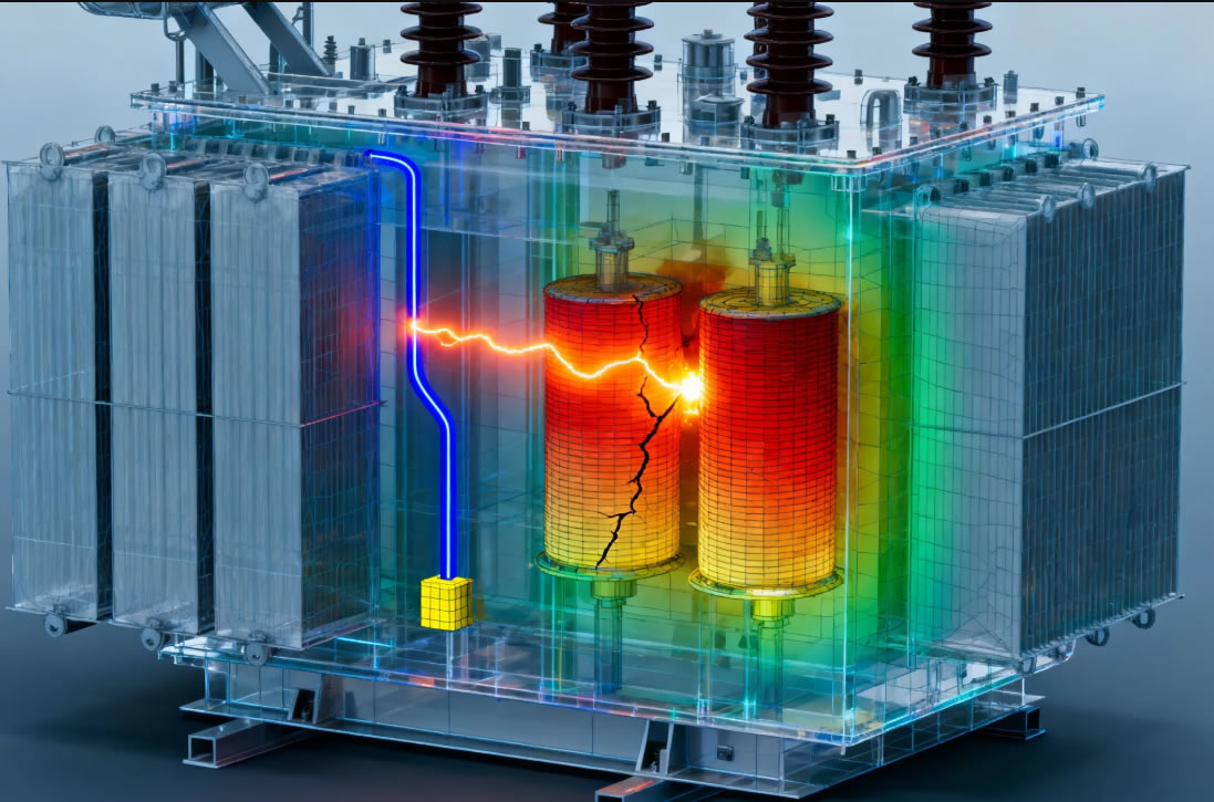
Installation Configuration Comparison
| Transformer Type | Overcurrent Protection Configuration | Surge Protection Configuration |
|---|---|---|
| Small Distribution Transformer (≤100 kVA) | Primary fuses + secondary breakers | Secondary-side Class II SPD |
| Medium Power Transformer (100-1000 kVA) | Primary breaker + overcurrent relays + secondary breakers | Primary and secondary Class I/II SPDs |
| Large Power Transformer (>1000 kVA) | Differential protection + overcurrent relays + שוברים | Lightning arresters + multi-stage SPD cascade |
| Critical Facility Transformer | Microprocessor-based protection + redundant breakers | Coordinated SPD system with continuous monitoring |
Tip: When planning protection system layouts, remember that surge devices need the shortest possible lead lengths to ground for effective operation, while overcurrent devices require proper current sensor placement for accurate measurement.
Main Function and Purpose
Understanding what each protection type actually does helps you appreciate why both are necessary for comprehensive transformer protection. Let’s break down the primary functions of each system.
What Overcurrent Protection Does
הגנת זרם יתר של שנאי serves as your first line of defense against electrical faults and abnormal operating conditions involving excessive current flow. This protection performs several critical functions:
- Monitors current magnitude: Continuously measures the current flowing through transformer windings and distribution circuits, comparing these values against predetermined safe limits
- Detects overload conditions: Identifies situations where load current exceeds the transformer’s rated capacity, which can cause dangerous overheating if allowed to continue
- Identifies short-circuit faults: Recognizes the extremely high currents that flow when insulation fails or conductors accidentally contact each other
- Provides time-delayed response: Allows brief overloads (like motor starting currents) while tripping on sustained overcurrent conditions
- Interrupts fault current: Opens circuits to stop current flow, preventing progressive damage to transformer windings, insulation systems, and connected equipment
- Enables selective coordination: Works with upstream and downstream protective devices to isolate faults at the most appropriate location, maintaining service to unaffected circuits
You can think of overcurrent protection as a vigilant guard that constantly watches current levels. When current stays within safe limits, the protection system remains passive. But when overloads or faults occur, it takes decisive action to interrupt power before damage occurs. The protection operates based on time-current characteristics—high overcurrents trigger fast tripping, while moderate overloads allow some delay for temporary conditions to clear.
What Surge Protection Does
Transformer surge protection addresses an entirely different threat—transient overvoltages that can reach thousands of volts above normal operating levels in microseconds. These protective systems perform specialized functions:
- Limits transient overvoltages: Clamps voltage spikes to safe levels that transformer insulation can withstand without damage
- Absorbs surge energy: Diverts the energy contained in voltage transients to ground, preventing it from reaching sensitive transformer components
- Protects against lightning: Handles the enormous voltage and current surges induced by direct and nearby lightning strikes
- Suppresses switching transients: Eliminates voltage spikes generated by circuit breaker operations, capacitor switching, and load interruptions
- Prevents cascade failures: Stops surges at their entry point, protecting not just the transformer but all downstream equipment
- Maintains voltage stability: Helps keep voltage within acceptable bounds during grid disturbances and fault conditions
Surge protection works like a pressure relief valve in a plumbing system. When voltage tries to rise above safe levels, the surge device creates a low-impedance path to ground, shunting the excess energy away from protected equipment. This happens so quickly—often in nanoseconds—that the voltage spike never has time to damage insulation or electronic components.
How the Functions Complement Each Other
Here’s where the distinction becomes crucial: overcurrent protection cannot protect against voltage surges because surges don’t necessarily involve high current in the protected circuit. באופן דומה, surge protection doesn’t respond to overcurrent conditions because voltage may remain normal even when excessive current flows. You need both systems working together:
| Scenario | Overcurrent Protection Response | Surge Protection Response |
|---|---|---|
| Lightning strike near transformer | No response (voltage spike, not current) | Activates to clamp voltage spike |
| Winding-to-winding short circuit | Trips immediately on high fault current | No response (current issue, not voltage) |
| Gradual load increase to 120% דֵרוּג | Time-delayed trip after thermal limit reached | No response (normal voltage) |
| Utility capacitor bank switching | No response (brief transient) | Suppresses voltage transient |
| Insulation failure from surge damage | Trips on resulting short-circuit current | Too late—damage already occurred |
פֶּתֶק: מוֹדֶרנִי intelligent transformer protection devices from manufacturers like FJINNO monitor both overcurrent and surge conditions, providing comprehensive protection with integrated diagnostics and communication capabilities.
Tip: When evaluating your transformer protection scheme, verify that you have adequate protection against both sustained overcurrent conditions and transient overvoltages. Relying on only one type leaves critical vulnerabilities that can lead to unexpected failures.
Transformer Overcurrent Protection Function
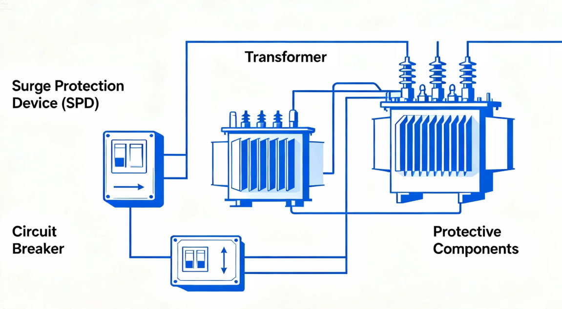
How Overcurrent Protection Works
Understanding the operating principles of overcurrent protection devices helps you select the right equipment and troubleshoot problems when they arise. These protective systems rely on fundamental electrical principles to detect and respond to abnormal current conditions.
Current Detection Mechanisms
כֹּל overcurrent protective device incorporates some method of sensing current magnitude. The detection approach varies depending on the device type and application requirements:
- Direct thermal sensing: In fuses and thermal-magnetic breakers, the current itself flows through a sensing element that heats up proportionally to current magnitude. When temperature exceeds a threshold, the device operates.
- Magnetic sensing: Circuit breakers use electromagnetic coils that create magnetic force proportional to current. High currents generate strong magnetic fields that mechanically trip the breaker.
- שנאים זרם (CTs): Protective relays use CTs to scale down the primary current to measurable levels while maintaining proportional representation of the actual current waveform.
- חיישני אפקט הול: Modern electronic protection devices employ solid-state sensors that measure magnetic fields around conductors, providing accurate current measurement without direct electrical connection.
- סלילי רוגובסקי: These flexible coil sensors wrap around conductors, measuring current through electromagnetic induction without requiring circuit interruption for installation.
Time-Current Characteristic Curves
One of the most important concepts in overcurrent protection is the relationship between current magnitude and operating time. Protective devices don’t trip instantly at the first hint of overcurrent—they follow carefully designed time-current curves that balance fast fault clearing against tolerance for temporary overloads.
When you examine a time-current curve, you’ll see how the device responds to different overcurrent levels:
- Thermal region (הגנת עומס יתר): At currents moderately above rating (100-600% בדרך כלל), the device operates with inverse time characteristics—higher currents cause faster operation. This allows harmless temporary overloads while protecting against sustained overcurrent.
- Magnetic region (short-circuit protection): At very high currents (בדרך כלל >600-1000% of rating), the device trips nearly instantaneously, clearing dangerous faults before they can cause significant damage.
- Coordination zones: The curves of upstream and downstream devices must be carefully spaced to ensure selective operation—only the device closest to the fault should trip under normal circumstances.
Thermal-Magnetic Circuit Breaker Operation
Let’s walk through what happens inside a typical thermal-magnetic circuit breaker when you experience different fault conditions. This helps you understand why breakers behave differently depending on the type of overcurrent:
During moderate overload (120-150% of rating):
- Current flows through a bimetallic strip, which consists of two metals with different thermal expansion rates bonded together.
- As current heats the strip, the differential expansion causes it to bend.
- After several seconds to minutes (depending on current magnitude), the strip bends far enough to release a mechanical latch.
- The latch releases a spring-loaded mechanism that opens the breaker contacts.
- The breaker trips, interrupting current flow and protecting the transformer from thermal damage.
During short-circuit fault (10-50 times rating):
- The enormous current creates a powerful magnetic field in the breaker’s electromagnetic coil.
- This magnetic force immediately pulls an armature that releases the trip mechanism.
- The breaker contacts begin separating within milliseconds (בדרך כלל 1-5 אלפיות השנייה).
- Arc chutes and deionization grids extinguish the resulting electrical arc.
- The fault current is interrupted before it can damage transformer windings or cause fires.
Electronic Overcurrent Relay Operation
מוֹדֶרנִי מערכות הגנת שנאים increasingly rely on microprocessor-based relays that offer sophisticated protection features beyond what simple breakers can provide. When you install an electronic overcurrent relay, here’s what happens:
- Continuous current sampling: The relay measures current thousands of times per second through current transformers, building a detailed picture of the current waveform.
- Digital signal processing: Microprocessors analyze the sampled data, calculating RMS current, peak values, and harmonic content.
- Comparison with settings: The relay compares measured values against user-programmed pickup settings and time-delay curves.
- Trip decision logic: When overcurrent conditions exceed settings for the specified time, the relay closes trip contacts that signal circuit breakers to open.
- הקלטת אירועים: The relay stores fault data including magnitude, מֶשֶׁך, and waveform captures for post-event analysis.
You can think of electronic relays as intelligent guardians that not only protect your transformer but also help you understand what happened when faults occur. Systems like FJINNO’s intelligent transformer protection devices integrate overcurrent protection with communication capabilities, allowing remote monitoring and diagnostics that simplify maintenance and troubleshooting.
Tip: When setting overcurrent protection parameters, always account for transformer inrush current, which can reach 8-12 times rated current for several cycles during energization. Your protection settings must allow for this temporary surge without nuisance tripping.
Types of Overcurrent Protection Devices
You’ll encounter several distinct categories of overcurrent protection devices in transformer applications, each with unique operating characteristics, יתרונות, and ideal use cases. Understanding these differences helps you select the most appropriate protection for your specific situation.
Fuses
Fuses represent the oldest and simplest form of overcurrent protection, yet they remain widely used due to their reliability, עלות נמוכה, and extremely fast operation on high-magnitude faults. When you install fuses for transformer protection, you’re utilizing a sacrificial device that permanently opens when excessive current flows through it.
Technical Characteristics
A fuse consists of a metal element (the fusible link) enclosed in a body filled with arc-quenching material. The element’s resistance causes it to heat when current flows. בתנאים רגילים, the heat dissipates harmlessly. During overcurrent conditions:
- The fusible element temperature rises rapidly
- At a specific temperature determined by the element’s material and geometry, the metal melts
- An electric arc forms across the gap where the element melted
- Arc-quenching sand or other materials absorb the arc energy and extinguish it
- Current flow stops, protecting the transformer
Types of Transformer Fuses
You’ll find several specialized fuse types designed specifically for transformer overcurrent protection:
- Current-limiting fuses: These fuses operate so quickly on high fault currents that they limit the peak current to values much lower than would otherwise flow. You’ll use these where fault current must be restricted to prevent mechanical damage.
- Expulsion fuses: Common on utility distribution transformers, these fuses expel ionized gases during operation, creating a visible indication of operation. The loud noise and flame discharge make the operation obvious.
- High-voltage power fuses: Designed for transformer primary protection on systems above 1000V, these fuses handle the high voltages and interrupting duties required for utility applications.
- Low-voltage fuses: Class RK5, י, ל, and T fuses protect transformer secondary circuits and connected loads in commercial and industrial facilities.
Response Speed and Characteristics
Fuses exhibit time-current characteristics similar to other protective devices, but with some unique features:
| Current Level (% of Rating) | Typical Operating Time | תרחיש יישום |
|---|---|---|
| 135% | 1 hour or more | Allows temporary overload, protects against sustained overcurrent |
| 200% | 1-10 פּרוֹטוֹקוֹל | Clears moderate faults while coordinating with downstream devices |
| 500% | 1-10 שניות | Rapidly clears serious faults |
| 2000%+ | 0.01-0.1 שניות | Current-limiting operation on major short circuits |
יתרונות ומגבלות
When you choose fuses for הגנת שנאי, you gain several benefits:
- Extremely fast clearing: Current-limiting fuses operate in less than a half-cycle on high fault currents
- No maintenance required: Fuses have no moving parts or mechanisms that require periodic servicing
- Consistent characteristics: Unlike breakers that may degrade with repeated operations, new fuses always perform to specification
- Low initial cost: Fuses typically cost much less than equivalent circuit breakers
- High interrupting ratings: Fuses can safely interrupt fault currents exceeding 200,000 amperes in some cases
אוּלָם, fuses also have important limitations you must consider:
- Single-operation devices: After operating, you must replace fuses—they cannot be reset like circuit breakers
- Single-phase operation possible: If only one fuse blows in a three-phase system, the transformer may single-phase, causing motor damage and imbalanced operation
- No adjustability: You cannot change fuse characteristics without physically replacing the device
- Replacement cost: While initial cost is low, repeated operations require purchasing new fuses
- Time to restore service: Finding and installing replacement fuses takes longer than resetting a circuit breaker
Tip: When using fuses for primary protection on transformers, always install three-phase trip mechanisms or fuse monitoring relays to detect single-phasing conditions and disconnect all phases when any one fuse operates.
Circuit Breakers
Circuit breakers have become the dominant overcurrent protection technology for most transformer installations due to their reusability, adjustability, ויכולות אינטגרציה. When you install a circuit breaker, you’re implementing a sophisticated electromechanical device that can interrupt fault current and be immediately restored to service.
Working Mechanism
Circuit breakers combine multiple technologies to detect and interrupt overcurrent:
- Thermal element: A bimetallic strip that bends when heated by current, providing inverse-time overload protection
- Magnetic element: An electromagnetic coil that generates force proportional to current, providing instantaneous short-circuit protection
- Arc interruption system: Arc chutes, deionization grids, and in some cases vacuum or SF6 gas chambers that safely extinguish the arc formed when contacts separate under load
- Operating mechanism: Spring-loaded contact assemblies and trip latches that convert the thermal or magnetic trip signal into mechanical contact opening
- Auxiliary contacts: Additional switch contacts that provide status indication and can interface with control systems
Types of Circuit Breakers for Transformer Protection
You’ll select from several circuit breaker categories depending on voltage, נוֹכְחִי, ודרישות היישום:
- Molded case circuit breakers (MCCBs): Available from 15A to 2500A, these enclosed breakers protect transformer secondary circuits and small transformer primaries up to about 600V. You’ll find adjustable thermal and magnetic trip settings on many models.
- Insulated case circuit breakers (ICCBs): These larger breakers (800A-5000A) offer more precise adjustability and higher interrupting ratings, suitable for protecting medium and large transformers.
- Low-voltage power circuit breakers (LVPCBs): The most sophisticated low-voltage breakers, featuring electronic trip units with extensive customization, מדידה, and communication capabilities. These protect large transformers and main service entrances.
- Medium-voltage circuit breakers: Vacuum or SF6 breakers designed for systems from 1kV to 38kV, commonly used for utility and industrial transformer primary protection. These breakers work with separate protective relays that provide the intelligence and decision-making.
Reusable and Adjustable Features
The key advantage that makes circuit breakers your first choice in most applications is their reusability. After a breaker trips:
- You investigate the cause of the trip
- You correct the fault condition or verify it was temporary
- You simply reset the breaker handle or pushbutton
- The transformer returns to service immediately
Modern breakers also offer extensive adjustability that fuses cannot match:
- Adjustable pickup current: Set the current level where overload protection begins
- Adjustable time delay: Control how long the breaker tolerates overload before tripping
- Adjustable instantaneous trip: Set the current threshold for immediate magnetic trip operation
- הגנה מפני תקלות קרקע: Many breakers include adjustable ground fault trip functions
- Maintenance mode settings: Some breakers allow temporary adjustment of trip characteristics during special conditions
תרחישי יישום
You’ll choose circuit breakers for transformer overcurrent protection when:
- The transformer serves critical loads where rapid restoration is essential
- You need the flexibility to adjust protection settings as load conditions change
- Integration with building or facility automation systems is required
- Nuisance tripping would be costly or disruptive, making fuse replacement unacceptable
- The installation requires routine switching operations in addition to fault protection
- You want local or remote indication of breaker status and trip history
פֶּתֶק: FJINNO’s intelligent transformer protection systems can interface with circuit breaker auxiliary contacts to provide comprehensive monitoring, recording trip events, and enabling remote breaker control for advanced applications.
Overload Relays and Protection Relays
Protective relays represent the most sophisticated approach to transformer overcurrent protection, separating the sensing and decision-making functions from the current interruption function. When you implement relay-based protection, you gain maximum flexibility, precision, and diagnostic capability.
ארכיטקטורת מערכת
A relay-based protection system consists of several components working together:
- שנאים זרם (CTs): Scale down primary current to standard 5A or 1A secondary current for relay measurement
- Protective relay: Monitors CT secondary current, applies protection logic, and issues trip commands when faults are detected
- Circuit breaker: Receives trip signals from the relay and physically interrupts the circuit
- DC control power: Provides reliable power for relay operation and breaker trip coils, independent of the AC system being protected
- Wiring and terminals: Connects all components and provides test points for commissioning and maintenance
Types of Overcurrent Relays
You’ll encounter several relay technologies, each with distinct characteristics:
- Electromechanical relays: Time-tested induction disk or plunger-type relays that operate through electromagnetic forces. While largely obsolete for new installations, you’ll still find these in older facilities.
- Static relays: Solid-state analog designs using discrete transistors and integrated circuits. More accurate and reliable than electromechanical types, but limited in flexibility.
- Microprocessor-based relays: Modern digital relays using sophisticated processors to implement complex protection algorithms. These devices offer features that were impossible with earlier technologies.
- Numerical relays: Advanced microprocessor relays with extensive metering, תִקשׁוֹרֶת, and self-diagnostic capabilities. These represent the current state-of-the-art in הגנת שנאי.
Protection Functions Available
מוֹדֶרנִי microprocessor-based overcurrent relays provide multiple protection elements in a single device:
- Phase overcurrent (ANSI 50/51): Time-overcurrent and instantaneous overcurrent protection for phase-to-phase and three-phase faults
- Ground overcurrent (ANSI 50N/51N): Specialized protection for ground faults, which may involve lower currents than phase faults
- Negative sequence overcurrent (ANSI 46): Detects unbalanced conditions that stress transformer windings
- Thermal overload (ANSI 49): Models transformer thermal capacity, preventing damage from cumulative heating effects
- Cold load pickup: Temporarily adjusts settings during restoration after extended outages when starting loads are high
- Current unbalance: Alerts to imbalanced loading that can cause overheating and reduced transformer life
Advanced Capabilities
When you specify modern relays for transformer overcurrent protection, you gain capabilities far beyond simple current measurement:
- Programmable logic: Create custom protection schemes using built-in logic functions
- הקלטת אירועים: Capture detailed fault data including pre-fault conditions, fault magnitude, and system response
- Oscillography: Record high-speed waveform data showing exactly what happened during disturbances
- פרוטוקולי תקשורת: Interface with SCADA systems, building automation, and asset management platforms via Modbus, DNP3, חברת החשמל 61850, and other protocols
- אבחון עצמי: Continuously monitor relay health and alert to potential problems before they cause protection failures
- Metering: Provide accurate measurement of current, כּוֹחַ, אֵנֶרְגִיָה, and power quality parameters
- Multiple setting groups: Store different protection settings for different operating modes and switch between them automatically or on command
Tip: Systems like FJINNO’s intelligent transformer protection devices integrate overcurrent relay functions with temperature monitoring, ניטור מפלס שמן, and communication capabilities, providing comprehensive protection and monitoring in compact, cost-effective packages ideal for distribution transformer applications.
Impact on Transformer Safety
The implementation of proper overcurrent protection directly determines whether your transformer operates safely throughout its intended service life or suffers premature failure. Understanding these safety impacts helps you appreciate why overcurrent protection deserves careful attention during design, הַתקָנָה, ותחזוקה.
Prevention of Winding Overheating
When current exceeds a transformer’s rated capacity, the copper or aluminum conductors in the windings heat up according to the I²R relationship—doubling the current quadruples the heating effect. This excessive heat causes multiple forms of damage:
- Insulation degradation: Transformer insulation follows the “ten-degree rule”—every 10°C increase above rated temperature roughly halves the insulation life. A transformer operating at 20°C above rating might last only 5 years instead of the expected 20+ שנים.
- Oil decomposition: In oil-filled transformers, excessive heat breaks down the insulating oil, forming sludge, acids, and moisture that further compromise insulation integrity.
- Mechanical stress: Thermal expansion and contraction from temperature cycling loosens winding clamping structures, allowing movement that can damage insulation during subsequent faults.
- Accelerated aging: Even if immediate failure doesn’t occur, cumulative thermal stress progressively weakens insulation until eventual breakdown occurs.
תָקִין overcurrent protection prevents these thermal damage mechanisms by limiting both the magnitude and duration of overcurrent conditions. The protection system ensures that any overload either remains within safe thermal limits or gets interrupted before cumulative damage occurs.
Avoidance of Insulation System Damage
The extremely high mechanical forces during short-circuit faults pose immediate threats to transformer insulation and structural integrity. When fault current flows—potentially reaching 20-30 times rated current—electromagnetic forces between conductors can exceed 100 times normal values. These forces can:
- Distort or collapse windings, crushing insulation between turns or layers
- Cause conductors to move within their insulation structures, abrading or puncturing insulation
- Generate vibrations that mechanically stress insulation systems and support structures
- Create hot spots where concentrated current causes localized overheating
Fast-acting overcurrent protection—particularly the instantaneous element of circuit breakers or current-limiting fuses—minimizes fault duration and therefore limits the mechanical energy that can damage transformer internals. The difference between a fault cleared in 0.05 seconds versus 0.5 seconds can mean the difference between minor stress and catastrophic structural failure.
Fire Risk Reduction
Transformer fires represent one of the most dangerous failure modes, threatening not just the transformer itself but potentially entire facilities and surrounding structures. Overcurrent conditions contribute to fire risk through several mechanisms:
- Overheated connections: Loose or undersized connections develop high resistance, creating localized hot spots that can ignite insulation or combustible materials. Overload protection helps by limiting the current through these problem connections.
- Winding insulation ignition: Sustained overheating can raise insulation temperature to its ignition point, starting internal fires that may be undetectable until catastrophic failure occurs.
- Oil fires: In oil-filled transformers, severe internal faults can vaporize insulating oil, creating flammable gases that may ignite or even explode if not quickly interrupted.
- Arc flash hazards: Uncleared faults expose maintenance personnel to dangerous arc flash events. Proper overcurrent protection limits arc duration and energy, reducing injury severity.
By quickly detecting and interrupting fault conditions, overcurrent protection devices serve as your primary defense against these fire scenarios. The protection system acts as an early-warning and automatic-response mechanism that stops problems before they escalate to dangerous levels.
אורך חיים מורחב של ציוד
Beyond preventing catastrophic failures, effective overcurrent protection extends transformer service life through several less obvious mechanisms:
- Reduced thermal cycling: By limiting overload magnitude and duration, protection systems minimize the temperature cycling that mechanically stresses insulation and connections.
- Preserved insulation integrity: Preventing overheating maintains insulation dielectric strength at design levels, ensuring the transformer can withstand normal voltage stresses and temporary overvoltages.
- Maintained oil quality: Limiting thermal stress preserves oil insulating properties and prevents formation of contaminants that accelerate aging.
- Protected tap changers: Overcurrent protection prevents tap changer operation under excessive load, avoiding contact damage and extending tap changer life.
- Reduced mechanical stress: Limiting fault current magnitude reduces the mechanical forces that can loosen clamping structures and damage winding geometry.
Economic studies consistently show that transformers with properly applied and maintained overcurrent protection last 25-40% longer than those with inadequate or poorly maintained protection. This extended life translates directly to lower total cost of ownership and reduced capital expenditure for premature replacements.
פֶּתֶק: מוֹדֶרנִי intelligent transformer protection systems like those from FJINNO combine overcurrent protection with thermal monitoring, providing comprehensive safeguarding against both immediate overcurrent threats and long-term thermal aging effects.
Transformer Surge Protection Function
How Surge Protection Works
בְּעוֹד overcurrent protection guards against sustained current problems, surge protection addresses an entirely different threat—transient overvoltages that can destroy insulation and sensitive electronics in microseconds. Understanding how surge protective devices operate helps you appreciate their critical role in comprehensive transformer protection.
The Nature of Voltage Surges
Before diving into protection mechanisms, you need to understand what you’re protecting against. Voltage surges—also called transients or spikes—are brief overvoltages that can reach thousands of volts above normal levels. These surges originate from several sources:
- Lightning strikes: Direct strikes to power lines or nearby strikes that couple energy into electrical systems through electromagnetic induction can generate surges exceeding 100,000 volts.
- Switching operations: Opening or closing circuit breakers, especially on inductive loads, creates voltage transients that propagate through the power system.
- Capacitor bank switching: Utility capacitor banks switching on and off generate characteristic oscillatory transients.
- Fault clearing: When protective devices interrupt fault current, the sudden current change induces voltage spikes in system inductance.
- Load rejection: Sudden loss of load, such as when a large motor trips offline, can cause voltage to temporarily spike.
What makes these surges so dangerous is their combination of high voltage and extremely fast rise time. While the surge may last only microseconds, the voltage can rise from normal levels to destructive levels in nanoseconds—far too fast for overcurrent devices to respond.
Voltage Clamping Principle
כֹּל surge protection devices work on the same fundamental principle: they create a low-impedance path to ground when voltage exceeds a predetermined threshold. Think of it like a pressure relief valve on a water system. When pressure (מֶתַח) builds too high, the valve (SPD) opens to release the excess, preventing damage to the system.
Here’s what happens when a voltage surge hits a protected transformer:
- Surge arrives: A lightning-induced surge enters the system, causing voltage to begin rising rapidly.
- SPD responds: When voltage reaches the device’s clamping voltage (בדרך כלל 1.3-2.0 times normal peak voltage), the SPD’s internal components change from high impedance to low impedance in nanoseconds.
- Current diversion: The surge current flows through the SPD to ground rather than through the transformer insulation.
- Voltage limitation: The SPD clamps voltage to a safe level—typically 2-3 times normal peak voltage—that transformer insulation can withstand.
- Energy absorption: The SPD dissipates the surge energy as heat in its internal components.
- Recovery: Once the surge passes, the SPD returns to its high-impedance state, ready for the next event.
This entire process happens in microseconds or even nanoseconds, protecting your transformer before the surge can cause damage.
Metal Oxide Varistor (MOV) Operation
Metal oxide varistors represent the most common technology in surge protective devices. Understanding how MOVs work helps you select and maintain these critical components.
An MOV consists of zinc oxide grains separated by grain boundaries that create numerous microscopic P-N junctions. Under normal voltage:
- These junctions act as insulators, presenting extremely high resistance (megohms)
- Only microamperes of leakage current flows through the MOV
- The device has negligible effect on normal system operation
When voltage exceeds the MOV’s clamping threshold:
- The grain boundary junctions begin conducting through quantum tunneling and avalanche breakdown
- Resistance drops from megohms to a few ohms in nanoseconds
- Surge current flows through the MOV instead of protected equipment
- The MOV limits voltage to its clamping level—typically 1.5-2.5 times nominal peak voltage
- After the surge passes, the junctions return to their insulating state
The beauty of MOV technology lies in its inherent self-acting nature—no external control circuits or power supplies are needed. The device responds automatically to overvoltage, making it highly reliable for transformer surge protection.
Gas Discharge Tube (GDT) Operation
Gas discharge tubes offer another approach to surge protection, particularly valuable for handling very high energy surges. When you need to protect against direct lightning strikes or severe switching transients, GDTs provide superior energy handling capability.
A GDT consists of two electrodes separated by an inert gas (typically argon or neon) within a sealed ceramic or glass envelope. Operation follows this sequence:
- Normal operation: Below the sparkover voltage, the gas acts as an insulator, and the GDT presents extremely high impedance (gigohms).
- Surge arrival: When voltage exceeds the sparkover threshold (typically 500-2500V depending on design), the electric field between electrodes becomes strong enough to ionize the gas.
- Arc formation: Once ionization begins, an electrical arc forms through the ionized gas, creating a low-impedance path (typically less than 1 ohm).
- Current conduction: The arc conducts surge current to ground, with voltage across the GDT dropping to a low arc voltage (typically 10-30V).
- Arc extinction: When surge current decreases below the GDT’s extinction current, the arc extinguishes and the device returns to its high-impedance state.
GDTs excel at handling high-energy surges because the arc can conduct thousands of amperes while dissipating minimal heat—the energy transfers to the gas rather than heating solid components. אוּלָם, GDTs have slower response times (microseconds rather than nanoseconds) and higher let-through voltage than MOVs, so you’ll often see both technologies combined in multi-stage protection schemes.
Avalanche Diode (TVS) Operation
Transient voltage suppressors (TVS diodes) use semiconductor avalanche breakdown to provide extremely fast voltage clamping. When you need to protect sensitive electronics associated with transformer control systems, TVS diodes offer response times measured in picoseconds.
TVS diodes are specially designed P-N junction devices that operate in reverse breakdown mode:
- Below breakdown voltage: The diode blocks current flow, presenting high impedance similar to any reverse-biased diode
- At breakdown voltage: Avalanche multiplication begins—electrons gain enough energy to knock other electrons free, creating a cascade effect
- Above breakdown: The diode conducts heavily in its breakdown region, clamping voltage while conducting surge current
- Thermal limit: The semiconductor junction must dissipate surge energy as heat; exceeding thermal capacity can destroy the device
You’ll find TVS diodes protecting the low-voltage control circuits, ממשקי תקשורת, and sensor inputs associated with modern transformer monitoring and protection systems. Their extremely fast response and precise clamping voltage make them ideal for sensitive electronics, though their relatively low energy handling capacity limits their use in primary power circuit protection.
Tip: מוֹדֶרנִי intelligent transformer protection systems מִן FJINNO incorporate multi-layer surge protection using coordinated combinations of MOVs, GDTs, and TVS diodes to provide comprehensive protection for both power circuits and sensitive control electronics.
Types of Surge Protection Devices
You’ll encounter several categories of surge protection devices in transformer applications, each designed for specific voltage levels, energy handling requirements, and installation locations. Understanding these classifications helps you design effective multi-stage protection schemes.
Metal Oxide Varistor (MOV) Surge Protectors
MOV-based surge protective devices dominate low and medium voltage transformer protection due to their excellent balance of performance, cost, ואמינות. When you specify MOV devices, you’re selecting proven technology that protects millions of transformers worldwide.
Technical Characteristics
MOV surge protectors offer several key performance parameters you’ll consider during selection:
- Maximum continuous operating voltage (MCOV): The highest voltage the MOV can withstand continuously without degradation—typically 115-125% of system nominal voltage
- Voltage protection rating (VPR): The maximum voltage let-through during a standard surge test—typically 1.5-2.5 times nominal voltage
- Surge current rating: The peak current the device can conduct without damage—ranging from 5kA to 200kA+ depending on device class
- Energy absorption capacity: The total energy the MOV can dissipate before failure—critical for locations with frequent surges
- זמן תגובה: MOVs typically respond in nanoseconds, providing protection before surges can damage equipment
Application in Transformer Protection
You’ll install MOV surge protective devices at multiple locations in transformer installations:
- Primary terminals: Protecting the high-voltage winding from utility-side transients and lightning-induced surges
- Secondary terminals: Guarding the low-voltage distribution system against surges propagating from either direction
- Control circuits: Protecting auxiliary power supplies, control wiring, and monitoring equipment
- ממשקי תקשורת: Safeguarding data lines connecting to remote monitoring or SCADA systems
יתרונות ומגבלות
MOV technology provides excellent surge protection with important benefits:
- Self-acting protection: No external power or control required for operation
- תגובה מהירה: Nanosecond clamping protects even fast-rising surges
- Low let-through voltage: Clamps voltage close to equipment withstand levels
- Compact size: High energy density allows small package sizes
- חסכוני: Lower cost than many alternative technologies
אוּלָם, MOVs have limitations you must understand:
- Degradation with use: Each surge absorbed causes minor degradation; cumulative damage eventually leads to failure
- Thermal runaway risk: Failed MOVs can overheat and potentially ignite if not protected by thermal disconnectors
- קיבול: MOVs present significant capacitance that may cause issues in some high-frequency applications
- Leakage current increase: As MOVs age, leakage current increases, potentially causing unwanted heating
פֶּתֶק: Always specify MOV-based SPDs with thermal disconnectors and status indicators so you know when the device has reached end-of-life and requires replacement.
Surge Protective Device (SPD) Classifications
International standards classify surge protective devices into categories based on their installation location and energy handling capability. Understanding this classification system helps you design coordinated protection schemes with proper devices at each level.
Class I SPDs (Lightning Current Arresters)
Class I surge protective devices—also called Type 1 SPDs in IEC standards—represent the first line of defense in multi-stage protection systems. You’ll install these devices at service entrances and transformer primaries where direct or nearby lightning strikes may induce extreme surge currents.
Class I SPD characteristics include:
- Very high surge current rating: Tested with 10/350 μs current waveform representing lightning strike characteristics; ratings from 25kA to 200kA
- Spark gap or GDT technology: Often use gas discharge tubes or spark gaps to handle the enormous energy
- High voltage protection level: Let-through voltage typically 2-4 kV to withstand without damage while dissipating massive energy
- Slower response time: May take several microseconds to activate, requiring coordination with faster downstream devices
You’ll specify Class I SPDs when:
- The transformer serves as main service entrance for a facility
- The installation is in a high-lightning-activity region
- The transformer connects to overhead distribution lines where lightning exposure is high
- Building codes or insurance requirements mandate lightning protection
Class II SPDs (Distribution Board Arresters)
Class II surge protective devices (Type 2 in IEC standards) provide protection at distribution panels and subfeeders throughout facilities. These represent the most common SPD application for transformer secondary protection.
Class II SPD features include:
- Medium surge current rating: Tested with 8/20 μs waveform; typical ratings 20kA to 80kA
- MOV-based technology: Usually employ metal oxide varistors for fast response and good let-through voltage
- Moderate voltage protection level: Typical let-through voltage 1-2 kV, protecting standard electrical equipment
- זמן תגובה מהיר: Nanosecond activation protects against fast-rising transients
Install Class II SPDs:
- At transformer secondary terminals
- In main distribution panels
- At subfeeders serving sensitive equipment areas
- Downstream of Class I devices in coordinated protection schemes
Class III SPDs (Point-of-Use Protectors)
Class III surge protective devices (Type 3 in IEC standards) provide final protection for individual pieces of sensitive equipment. While less common in transformer protection specifically, you’ll use these devices to protect instrumentation and control equipment associated with transformer monitoring systems.
Class III SPD characteristics:
- Lower surge current rating: Tested with 1.2/50 μs voltage waveform and 8/20 μs current waveform; typical ratings 3kA to 20kA
- Very low voltage protection: Let-through voltage optimized for sensitive electronics, typically 500V-1000V
- תגובה מהירה: Often combine MOVs with TVS diodes for fastest possible clamping
- Low energy capacity: Must be coordinated with upstream SPDs to avoid overload
Coordinated Multi-Stage Protection
For optimal protection, you’ll implement coordinated schemes using multiple SPD classes:
| Protection Stage | SPD Class | מיקום התקנה | פונקציה ראשית |
|---|---|---|---|
| שָׁלָב 1 | כיתה א' | Transformer primary/service entrance | Handle direct lightning and extreme surges |
| שָׁלָב 2 | Class II | Transformer secondary/distribution panels | Protect against switching transients and residual lightning energy |
| שָׁלָב 3 | Class III | Sensitive equipment locations | Final protection for electronics and instrumentation |
Proper coordination requires maintaining adequate cable length (בדרך כלל 10-15 meters minimum) between protection stages to ensure surge energy dissipates in upstream devices before reaching downstream protection.
Lightning Arresters for High-Voltage Transformers
Lightning arresters—sometimes called surge arresters—represent specialized surge protection designed specifically for medium and high voltage transformer applications. When you’re protecting utility distribution transformers or industrial transformers operating above 1kV, arresters provide the robust protection these installations require.
Arrester Technologies
Modern lightning arresters employ several proven technologies:
- Metal oxide arresters: Use stacks of zinc oxide disks in series to achieve the high voltage rating needed for distribution systems (2.5kV to 800kV). These gapless arresters provide superior protection and reliability compared to older silicon carbide designs.
- Polymer-housed arresters: Enclose the MOV elements in polymer housings that provide excellent contamination resistance and reduced weight compared to porcelain. You’ll prefer these for coastal or industrial environments with high pollution levels.
- Porcelain-housed arresters: Traditional design using porcelain insulators. Still widely used and preferred in some utilities due to proven long-term reliability and visible damage indication.
Installation Practices
תָקִין lightning arrester installation is critical for effective transformer protection:
- מִקוּם: Mount arresters as close as possible to transformer terminals—ideally within 3 meters—to minimize voltage rise in connecting leads during surge events
- Grounding: Connect arrester ground terminals to the transformer tank and ground grid with the shortest possible conductor—long ground leads compromise protection effectiveness
- Lead dress: Route line-side conductors carefully to avoid creating inductive loops that increase lead voltage drop
- Mechanical support: Ensure adequate mechanical strength to withstand short-circuit forces and wind loading
Rating Selection
When specifying lightning arresters for transformer surge protection, you’ll select based on several parameters:
- Maximum continuous operating voltage (MCOV): Must exceed the maximum system voltage under all operating conditions, including temporary overvoltages
- Discharge current rating: Typically 10kA or 20kA for distribution applications; higher ratings for transmission systems
- Energy absorption capability: Must handle expected surge energy without damage or excessive temperature rise
- Voltage protection level: Should limit voltage to below transformer BIL (Basic Insulation Level) rating with adequate safety margin
Tip: For comprehensive protection of medium-voltage transformers, combine lightning arresters on the high-voltage side with Class I/II SPDs on the low-voltage side. This coordinated approach protects against surges arriving from either direction.
Role in System Protection
יָעִיל surge protection provides benefits extending far beyond the transformer itself, contributing to overall power system reliability and equipment longevity. Understanding these broader impacts helps justify surge protection investments and optimal implementation.
Protection of Sensitive Electronic Equipment
Modern facilities increasingly depend on electronic equipment that’s far more vulnerable to voltage transients than traditional electromagnetic devices. While a transformer might withstand brief overvoltages, the power supplies, כונני תדר משתנה, programmable logic controllers, and computer equipment it serves can fail from surges well below the transformer’s withstand capability.
When you implement comprehensive transformer surge protection, you’re creating a protective umbrella that safeguards:
- Building automation systems: HVAC controls, lighting controls, and security systems that increasingly rely on sensitive microprocessor-based equipment
- Information technology infrastructure: Servers, network switches, and telecommunications equipment requiring clean power for reliable operation
- Industrial control systems: PLCs, SCADA equipment, and process controllers managing critical production operations
- Medical equipment: Diagnostic devices and patient monitoring systems where surge-induced failures can compromise patient safety
- Laboratory instrumentation: Research and analytical equipment with precision electronics vulnerable to even modest voltage transients
The economics are compelling: a properly specified surge protection system costing a few thousand dollars can protect millions of dollars of sensitive electronic equipment connected downstream of the transformer.
Prevention of Lightning-Induced Damage
Lightning represents the most severe transient threat most installations face. While direct strikes to buildings are relatively rare, nearby strikes and strikes to overhead power lines couple enormous energy into electrical systems. Without adequate surge protection, this energy can:
- Puncture transformer insulation, causing immediate catastrophic failure
- Damage tap changer mechanisms and switching contacts
- Destroy control electronics and monitoring equipment
- Cause fires in transformer oil or surrounding materials
- Propagate through the distribution system, damaging multiple pieces of equipment simultaneously
Statistics from insurance companies show that lightning-related equipment damage accounts for 20-30% of all transformer failures in regions with moderate to high lightning activity. Proper surge protection can reduce this failure rate by 80-90%, translating to substantial savings in replacement costs and avoided downtime.
Elimination of Switching Transient Interference
Beyond lightning, everyday switching operations generate voltage transients that accumulate damage over time. פעולות מפסק זרם, capacitor bank switching, motor starting, and fault clearing all create voltage spikes that stress insulation and disrupt sensitive equipment.
Surge protective devices suppress these operational transients, providing multiple benefits:
- Extended insulation life: By limiting voltage stress, SPDs reduce cumulative insulation degradation that would otherwise lead to premature failure
- Reduced equipment nuisance trips: Many electronic drives and power supplies have overvoltage protection that can cause shutdowns during transient events; surge protection prevents these interruptions
- Improved power quality: Suppressing transients reduces electromagnetic interference that can cause data errors and communication problems
- Better coordination: With transients controlled, protective device coordination schemes work as designed rather than experiencing unexpected interactions
Enhanced System Reliability
The cumulative effect of comprehensive surge protection is measurably improved system reliability. Facilities implementing coordinated multi-stage surge protection report:
- 40-60% reduction in equipment failures attributed to electrical disturbances
- Decreased frequency of unexplained trips and system malfunctions
- Extended service life for transformers, מיתוג, and electronic equipment
- Lower maintenance costs due to reduced component replacement
- Improved uptime for critical processes and reduced lost production
For critical facilities—data centers, בתי חולים, emergency services, continuous process industries—these reliability improvements often justify surge protection investments through avoided outage costs alone, even before considering equipment replacement savings.
פֶּתֶק: מוֹדֶרנִי intelligent transformer protection systems מִן FJINNO integrate surge protection monitoring with overcurrent protection and other diagnostic functions, providing comprehensive visibility into all threats to transformer health and enabling proactive maintenance strategies.
Transformer Overcurrent Protection VS Transformer Surge Protection: Detailed Comparison
Protection Target Differences
The most fundamental distinction between overcurrent protection ו surge protection lies in the completely different electrical phenomena each system addresses. Understanding these target differences helps you recognize why both protection types are essential and cannot substitute for each other.
Overcurrent Protection Targets
הגנת זרם יתר של שנאי focuses on current-related threats that develop over time scales ranging from continuous conditions to several cycles of the power frequency:
| סוג איום | מאפיינים | Typical Duration | Damage Mechanism |
|---|---|---|---|
| Sustained Overload | 110-150% of rated current | Minutes to hours | Cumulative thermal damage to insulation |
| Temporary Overload | 150-300% of rated current | Seconds to minutes | הזדקנות מואצת של בידוד |
| Phase-to-Phase Fault | 5-20 times rated current | Cycles to seconds | Mechanical damage, arc damage, thermal destruction |
| תקלת קרקע | מִשְׁתַנֶה, often lower than phase faults | Cycles to seconds | Insulation carbonization, fire hazard |
| Winding-to-Winding Fault | Extremely high, limited by impedance | Cycles | Catastrophic winding destruction |
Notice that all these threats involve abnormal current magnitude persisting for at least several power frequency cycles. Even the fastest short-circuit faults that overcurrent protection must clear exist for at least 16-20 milliseconds on 60Hz systems (one cycle). This time scale allows electromechanical and electronic protection devices to sense, decide, and respond.
Surge Protection Targets
Transformer surge protection addresses voltage-related threats occurring on time scales thousands of times faster than overcurrent phenomena:
| סוג איום | מאפיינים | Typical Duration | Damage Mechanism |
|---|---|---|---|
| Lightning-Induced Surge | Up to 100kV+, extremely fast rise | 1-100 microseconds | Insulation puncture, הבזק, component destruction |
| Switching Transient | 2-5 times normal voltage | Microseconds to milliseconds | Cumulative insulation stress, electronic upset |
| Capacitor Switch Oscillation | High-frequency voltage oscillations | אלפיות שניות | Resonance damage, electronic interference |
| Fault-Clearing Transient | 3-4 times normal voltage | מיקרו-שניות | Insulation stress, arrester duty |
| Ferroresonance | Sustained overvoltage at harmonics | Continuous until cleared | Core saturation, התחממות יתר, insulation damage |
These voltage transients happen so quickly that overcurrent devices cannot respond in time. By the time a circuit breaker could even begin to move, the surge has already either caused damage or been safely dissipated by surge protection devices.
Why Both Protection Types Are Essential
The target differences make clear why you need both protection systems working together:
- Overcurrent protection cannot protect against surges: A 10kV surge lasting 10 microseconds won’t trip overcurrent devices because current magnitude may be low and duration too brief for thermal or electromagnetic mechanisms to respond.
- Surge protection cannot protect against overcurrent: א 200% overload that will eventually destroy insulation through heating produces normal voltage levels, so surge devices won’t activate.
- Some faults need both: Lightning strikes may cause insulation failure that then creates short circuits. Surge protection limits the initial voltage transient, while overcurrent protection clears the resulting fault current.
- Coordination is critical: Surge protection extends transformer life by preventing insulation degradation that would eventually cause faults requiring overcurrent protection to clear.
Tip: When conducting transformer protection audits, verify that you have adequate protection against both sustained/repetitive overcurrent conditions AND transient overvoltages. Finding one type of protection without the other indicates a serious gap in your protection philosophy.
Response Time Comparison
The dramatically different response speeds of overcurrent protection נֶגֶד surge protection reflect the different time scales of the threats they address. Understanding these timing differences helps you appreciate the specialized nature of each protection type.
Overcurrent Protection Response Times
Overcurrent protective devices operate on time scales ranging from milliseconds to seconds, matching the duration of the current-related threats they protect against:
| Device Type | Response Time Range | גורמים משפיעים |
|---|---|---|
| Current-Limiting Fuses | 0.25-8 אלפיות השנייה | Current magnitude, pre-loading, fuse type |
| מפסק חשמל (מַגנֶטִי) | 1-5 אלפיות השנייה | Current magnitude, breaker size, mechanism type |
| מפסק חשמל (תֶרמִי) | Seconds to minutes | Overcurrent magnitude, טמפרטורת הסביבה, pre-loading |
| Electronic Overcurrent Relay | 15-50 אלפיות השנייה + breaker time | Settings, current magnitude, CT accuracy |
| Electromechanical Relay | 50-500 אלפיות השנייה + breaker time | Relay type, current magnitude, spring tensions |
Even the fastest overcurrent devices—current-limiting fuses operating on severe short circuits—require at least one-quarter of a power frequency cycle to clear faults. This speed is entirely adequate for current-related threats but hopelessly slow for voltage transients.
Surge Protection Response Times
Surge protective devices must respond orders of magnitude faster to clamp voltage before insulation damage occurs:
| Device Type | זמן תגובה | Voltage Clamping Speed |
|---|---|---|
| TVS Diodes | 1-5 picoseconds | Essentially instantaneous |
| Metal Oxide Varistors | 1-50 nanoseconds | Clamps in less than 1 nanosecond after threshold |
| Gas Discharge Tubes | 100-500 nanoseconds | Arc formation determines clamping speed |
| Spark Gaps | 0.5-5 microseconds | Dependent on gap spacing and voltage rise rate |
| מעצורי ברק | Nanoseconds (gapless MOV type) | Sub-microsecond clamping |
Notice that surge device response times are measured in billionths or millionths of a second—thousands to millions of times faster than overcurrent protection. This speed is absolutely necessary because voltage transients rise to destructive levels in similarly short time frames.
Practical Implications of Response Time Differences
The vast difference in response speeds has several important practical consequences:
- No overlap in capabilities: Overcurrent devices are far too slow to provide any surge protection, while surge devices don’t measure or respond to sustained current levels.
- Coordination challenges: When designing protection schemes involving both types, you must ensure surge devices don’t inadvertently bypass overcurrent protection or vice versa.
- Testing differences: Overcurrent device testing uses standard test currents applied for measurable time periods. Surge device testing requires specialized pulse generators creating microsecond-duration impulses.
- Failure modes differ: Slow-acting overcurrent devices may fail closed (stuck contacts) or open (burned fuses). Fast-acting surge devices typically fail short-circuit, which is why they need backup overcurrent protection.
פֶּתֶק: מוֹדֶרנִי intelligent transformer protection systems מִן FJINNO monitor both overcurrent and surge events despite their vastly different time scales, providing comprehensive protection visibility and coordinated response to all electrical threats.
Operating Mechanism Comparison
Beyond the different threats they address and speeds at which they operate, overcurrent protection ו surge protection employ fundamentally different operating mechanisms that reflect their specialized functions.
Overcurrent Protection Mechanisms
Overcurrent protection devices operate by detecting current magnitude and interrupting current flow when thresholds are exceeded:
- Current sensing: All overcurrent devices measure current magnitude through some mechanism—thermal heating, magnetic force, or electronic measurement via current transformers
- Threshold comparison: The measured current is compared against predetermined safe limits, either through calibrated mechanical elements or programmed electronic settings
- Time delay application: Most devices incorporate time delays that allow brief overcurrent while protecting against sustained conditions
- Circuit interruption: When overcurrent persists beyond allowed time, the device physically opens the circuit, stopping current flow
- Arc extinction: The device must safely extinguish the electrical arc that forms when contacts separate under load
The key point: overcurrent protection works by opening the circuit—literally creating an air gap or vacuum space that current cannot cross. This approach works because the threats being addressed persist long enough for mechanical mechanisms to operate.
Surge Protection Mechanisms
Surge protection devices use entirely different principles because they must respond before mechanical mechanisms could possibly move:
- Voltage sensing: Surge devices respond to voltage exceeding thresholds, not current magnitude
- Impedance switching: Rather than opening circuits, surge devices change from high impedance (blocking) to low impedance (conducting) when voltage exceeds safe levels
- Current diversion: Surge devices shunt excess energy to ground rather than interrupting the circuit
- Voltage clamping: The devices limit voltage to safe levels while allowing surge current to flow through them
- Automatic recovery: After the surge passes, devices automatically return to high-impedance state without manual reset
The fundamental difference: surge protection never opens the circuit. במקום זאת, it provides a parallel path to ground that activates only during overvoltage conditions. This approach allows microsecond response speeds that would be impossible for mechanical circuit interruption.
Series vs. Parallel Connection
The different operating mechanisms dictate different connection methods:
| אַספֶּקט | Overcurrent Protection | Surge Protection |
|---|---|---|
| Connection Type | Series with protected circuit | Parallel between line and ground |
| פעולה רגילה | Conducts all load current | Blocks current (high impedance) |
| During Fault/Surge | Opens circuit, stops current flow | Conducts surge current to ground |
| After Operation | Remains open until manually reset (שוברים) or replaced (נתיכים) | Automatically returns to blocking state |
| Effect on Circuit | Completely de-energizes protected equipment | Allows normal operation to continue |
This fundamental architectural difference means the two protection types complement rather than compete with each other—each performs functions the other cannot.
Energy Handling Differences
The operating mechanisms also determine how each device handles fault energy:
- Overcurrent devices: Prevent energy from reaching protected equipment by stopping current flow. The fault energy is dissipated in the source impedance and in the arc created during contact opening. The device itself may experience thermal and mechanical stress but doesn’t absorb the bulk of the fault energy.
- Surge devices: Absorb surge energy internally, converting it to heat in the device’s active elements (MOV disks, TVS junction, GDT arc). The protected equipment sees reduced voltage but the surge device must dissipate potentially enormous energy in microseconds.
This energy handling difference explains why surge devices have limited surge current capacity and degrade with repeated operations, while properly applied overcurrent devices can interrupt faults repeatedly without degradation (within their interrupting rating).
דרישות התקנה
The different operating principles of overcurrent protection ו surge protection create distinct installation requirements you must follow for effective protection.
Overcurrent Protection Installation
When installing overcurrent protective devices, you’ll focus on proper current path and circuit interruption capability:
- Series connection integrity: All load current must flow through the protective device—parallel paths or bypasses defeat the protection
- Adequate interrupting rating: The device must be able to safely interrupt the maximum available fault current at its installation location
- Proper conductor sizing: Connections to and from the device must handle full load current without overheating
- Torque specifications: Terminal connections require proper torque to prevent high-resistance connections that could cause false trips or device failure
- Short-circuit current calculation: Available fault current must be calculated to verify device ratings are adequate
- Coordination study: Device settings must be coordinated with upstream and downstream protection to ensure selective operation
- Ambient temperature consideration: Device ratings may need derating in high-temperature environments
Surge Protection Installation
Surge protective device installation demands very different attention to detail:
- Lead length minimization: Total lead length (line-side conductor + ground conductor) should be kept below 0.5 meters to prevent inductive voltage rise during fast surges
- Ground connection quality: Ground connection impedance is critical—use shortest, straightest conductor possible with no sharp bends
- Proper grounding point: SPD should connect to the same grounding point as protected equipment to avoid creating ground loops
- Cascading distances: Multi-stage protection requires adequate cable length (10-15m minimum) between stages for proper energy sharing
- Voltage rating matching: SPD voltage ratings must match system voltage, accounting for temporary overvoltages
- Overcurrent backup protection: SPDs need upstream overcurrent protection (fuses or breakers) to interrupt power if the SPD fails short-circuit
- Status indication access: Mount SPDs where status indicators are visible or connected to monitoring systems
Common Installation Mistakes
Understanding common errors helps you avoid compromising protection effectiveness:
| Mistake | Consequence | Correct Practice |
|---|---|---|
| Long SPD lead lengths | Reduced protection effectiveness, high let-through voltage | Keep total lead length under 0.5m, use direct connections |
| Undersized overcurrent device | Nuisance tripping, inability to utilize full transformer capacity | Size based on transformer rating plus acceptable overload |
| SPD without backup fuse | Failed SPD creates bolted fault, no protection | Always provide upstream overcurrent protection for SPDs |
| Inadequate breaker interrupting rating | Breaker explosion during fault, personnel hazard | Calculate available fault current, verify rating adequacy |
| Poor SPD grounding | Surge energy not effectively diverted, נזק לציוד | Use shortest ground conductor, verify low impedance |
Tip: When installing combined protection systems, ensure that overcurrent device placement doesn’t interfere with surge device effectiveness. SPDs should connect as close to protected equipment as practical, with overcurrent protection upstream of the protected equipment but potentially either upstream or downstream of the SPD depending on coordination requirements.
Coordination and Integration
בְּעוֹד overcurrent protection ו surge protection address different threats through different mechanisms, they must work together harmoniously in comprehensive transformer protection schemes. Understanding coordination principles helps you design integrated systems that provide maximum protection without unwanted interactions.
Complementary Protection Functions
The two protection types work together in a complementary relationship:
- Surge protection extends transformer life: By limiting voltage stresses, surge devices prevent cumulative insulation degradation that would eventually cause failures requiring overcurrent protection to clear
- Overcurrent protection backs up surge protection: If a surge device fails short-circuit (a common failure mode), overcurrent protection isolates the failed device
- Coordinated response to lightning: Lightning may first cause a voltage surge that surge devices suppress, followed by a fault current from any insulation damage that overcurrent devices must clear
- Combined monitoring value: Tracking both surge activity and overcurrent events provides comprehensive visibility into transformer stress factors
Avoiding Unwanted Interactions
Improper integration can create problems where protection systems interfere with each other:
- SPD failure causing overcurrent device nuisance trips: If SPD backup overcurrent protection is too sensitive, leakage current increase in aging SPDs may cause false trips. פִּתָרוֹן: size backup protection appropriately for end-of-life SPD leakage.
- Overcurrent device impedance affecting surge protection: Very high impedance overcurrent sensing (some CTs) can create voltage rise during surges. פִּתָרוֹן: verify CT burden doesn’t compromise surge protection.
- Ground loops between protection systems: Separate grounds for overcurrent and surge protection can create circulating currents. פִּתָרוֹן: connect all protection to common ground point.
- Inadequate fault current for overcurrent operation: Some ground faults produce currents below overcurrent device pickup but high enough to damage equipment. פִּתָרוֹן: implement sensitive ground fault protection or residual current monitoring.
Integrated Monitoring and Control
Modern protection systems increasingly integrate overcurrent and surge protection into unified platforms:
- Combined monitoring panels: Display status of both overcurrent devices (circuit breaker position, current levels) and surge devices (SPD status, surge counter readings)
- Coordinated alarm systems: Alert operators to any protection system abnormalities through single monitoring interface
- Data correlation: Analyze relationships between surge events and subsequent overcurrent trips to identify surge-induced failures
- תחזוקה חזויה: Track both surge exposure and thermal/overcurrent stress to optimize transformer maintenance timing
- Communication integration: Interface both protection types with SCADA or building automation via common protocols
FJINNO’s intelligent transformer protection systems exemplify this integrated approach, combining overcurrent relaying, surge monitoring, חישת טמפרטורה, and communication capabilities in unified devices that simplify installation while providing comprehensive protection visibility.
Protection Philosophy Integration
Effective coordination requires thinking holistically about transformer protection:
- Identify all threats: List every potential failure mode—overcurrent, surge, תֶרמִי, מֵכָנִי, environmental
- Assign protection responsibilities: Determine which protection type addresses each threat most effectively
- Verify complete coverage: Ensure no threats fall through gaps between protection systems
- Check for redundancy: Identify where multiple protection types provide backup for critical threats
- Validate coordination: Confirm protection systems don’t interfere with each other or create new vulnerabilities
- Plan maintenance: Establish testing schedules that maintain all protection types in functional condition
- Document the system: Create drawings and descriptions showing how all protection elements work together
This systematic approach ensures your transformer benefits from truly comprehensive protection rather than a collection of independent devices that may or may not work together effectively.
Common Issues & תַחזוּקָה
Overcurrent Protection Problems
Even properly specified and installed overcurrent protection devices can develop problems that compromise their protective function. Recognizing common issues and implementing effective maintenance practices ensures your overcurrent protection remains reliable throughout the transformer’s service life.
Common Overcurrent Protection Issues
| Issue | Cause | תסמינים | פִּתָרוֹן |
|---|---|---|---|
| Nuisance Tripping | Settings too sensitive, high inrush current, temporary overloads | Repeated trips during normal starting or brief overloads | Adjust settings, add time delay, verify load calculations |
| Failure to Trip | Mechanism wear, contact welding, incorrect settings | Overcurrent conditions persist without protection operation | Test device operation, inspect contacts, verify settings |
| Intermittent Operation | Loose connections, dirty contacts, marginal settings | Inconsistent response to similar overcurrent levels | Tighten connections, clean contacts, review settings |
| Single-Phasing | One fuse blown or one pole failed | Motor damage, voltage imbalance, abnormal heating | Install phase-failure monitoring, use 3-pole breakers |
| Contact Deterioration | Repeated fault clearing, normal aging | Increased resistance, heating, unreliable operation | Regular contact inspection, schedule replacement |
| סחף כיול | Thermal element aging, עייפות אביב | Trip point differs from settings | Periodic testing and recalibration |
Preventive Maintenance Practices
Regular maintenance keeps overcurrent protective devices functioning reliably. Follow this maintenance checklist:
- Quarterly visual inspection:
- Check for physical damage, קורוזיה, or contamination
- Verify indicator lights and displays function correctly
- Listen for abnormal sounds (זמזום, clicking) indicating loose components
- Look for discoloration or signs of overheating at terminals
- Annual electrical testing:
- Measure contact resistance to verify acceptable values
- Test trip characteristics using primary current injection
- Verify ground fault protection operates at correct levels
- Check auxiliary contact operation and wiring integrity
- Connection maintenance:
- Thermographic inspection to identify hot connections
- Torque verification using calibrated torque wrenches
- Tighten any loose terminals to manufacturer specifications
- Clean and treat connections showing corrosion
- Mechanism inspection:
- Manually operate breakers to verify smooth mechanism action
- Lubricate pivot points and sliding surfaces per manufacturer instructions
- Check spring tensions and replace weakened springs
- Verify latch engagement and release function properly
- Electronic relay maintenance:
- Download and analyze event logs for unusual patterns
- Verify communication links to SCADA or monitoring systems
- Test self-diagnostic functions and address any alarms
- Update firmware if manufacturer issues critical patches
Record Keeping
Maintain detailed records of all overcurrent protection maintenance and operations:
- Date and results of all inspections and tests
- Trip event log with date, זְמַן, and apparent cause
- Any setting changes with justification
- Repairs or component replacements performed
- Thermographic survey results showing connection temperatures
These records help identify degradation trends and support decisions about device replacement timing.
Tip: After any overcurrent device operation, always investigate the root cause before simply resetting and returning to service. Repeated operations on actual faults indicate a problem needing correction, while nuisance trips suggest settings need adjustment. FJINNO’s intelligent protection systems automatically log trip events with detailed pre-fault data to support effective troubleshooting.
Surge Protection Problems
Surge protective devices face unique challenges because they must absorb enormous energy in microseconds while remaining ready for the next surge. Understanding SPD failure modes and maintenance requirements ensures your surge protection remains effective.
Common Surge Protection Issues
| Issue | Cause | תסמינים | פִּתָרוֹן |
|---|---|---|---|
| SPD Degradation | Cumulative surge exposure, multiple large surges | Increased leakage current, status indicator changes | Replace SPD, improve upstream protection |
| Protection Failure | SPD end-of-life, improper installation, exceeded rating | Equipment damage during surges, SPD appears open-circuit | Replace SPD, verify proper sizing and installation |
| SPD Short Circuit | Catastrophic surge, manufacturing defect, הְזדַקְנוּת | Backup fuse/breaker trips, loss of power | Replace SPD, inspect for external surge sources |
| Ground Connection Issues | קורוזיה, loose connections, inadequate conductor size | Reduced protection effectiveness, high let-through voltage | Clean and tighten ground connections, verify conductor sizing |
| Inappropriate Status | Internal component failure, indicator mechanism fault | Status indicator doesn’t match actual SPD condition | Test SPD parameters, replace if failed |
| Coordination Problems | Improper cascading, inadequate separation distances | Lower-stage SPDs fail before upstream devices activate | Verify cascade coordination, add separation impedance |
Surge Protection Maintenance Checklist
Implement these maintenance practices to maximize SPD reliability and service life:
- Quarterly visual inspection:
- Check status indicators—green typically means functional, red indicates replacement needed
- Inspect for physical damage, סדקים, או סימני התחממות יתר
- Verify nameplate data matches system voltage
- Check that thermal disconnectors (אם קיים) haven’t activated
- Annual electrical testing:
- Measure leakage current—increasing values indicate approaching end-of-life
- Test clamping voltage using surge generator (requires specialized equipment)
- Verify ground connection impedance remains below 1-2 ohms
- Document surge counter readings if available
- After major surge events:
- Inspect all SPDs immediately following lightning storms or switching incidents
- Test leakage current to detect cumulative damage
- Replace any SPDs showing status indicator changes
- Document the event date for service life tracking
- Connection maintenance:
- Verify all connections remain tight—loose connections increase impedance
- Clean ground connections and treat with anti-oxidant compound
- Check that lead lengths haven’t been altered during other work
- Ensure SPD mounting remains secure
- Environmental protection:
- Verify enclosure seals prevent moisture ingress
- Check ventilation openings aren’t blocked (for units needing cooling)
- Inspect for corrosion in coastal or industrial environments
- Clean accumulated dust or contamination from enclosures
SPD Replacement Criteria
Replace surge protective devices when any of these conditions occur:
- Status indicator shows failure or end-of-life condition
- Leakage current exceeds manufacturer’s end-of-life threshold (typically 1-2mA)
- Clamping voltage testing shows degraded performance
- Physical damage to housing, terminals, or internal components
- After a known severe surge event, even if status appears normal
- חיי שירות (years in operation) exceeds manufacturer recommendations
- Surge counter (if equipped) shows exposure exceeding rated surge capacity
Seasonal Considerations
In regions with seasonal thunderstorm activity, implement enhanced maintenance before and after storm season:
- Pre-season preparation:
- Replace any marginal SPDs before storm season begins
- Test all surge protection to verify full functionality
- Stock replacement SPDs for critical locations
- Review and update surge event response procedures
- Post-season inspection:
- Thoroughly test all SPDs after storm season ends
- Replace devices showing degradation even if still functional
- Analyze any surge-related equipment failures
- Update protection schemes based on seasonal experience
פֶּתֶק: מוֹדֶרנִי intelligent transformer protection systems מִן FJINNO include integrated SPD monitoring that tracks surge events, monitors SPD status remotely, and provides predictive replacement alerts—eliminating the need for manual inspection while ensuring timely SPD replacement before protection is compromised.
Importance in Transformer Systems
Working Together for Comprehensive Protection
The true power of effective transformer protection emerges when you understand how overcurrent protection ו surge protection work together to create a comprehensive defense against the full spectrum of electrical threats. Neither system alone provides adequate protection—you need both working in coordination to safeguard your transformer investment.
The Complete Protection Cycle
Imagine what happens when multiple threats occur in sequence. Understanding this helps you appreciate why integrated protection is essential:
- Lightning surge arrives: A nearby lightning strike induces a voltage transient on overhead lines feeding your transformer.
- Surge protection activates: SPDs clamp the voltage to safe levels within nanoseconds, preventing immediate insulation damage.
- Minimal stress occurs: The transformer insulation experiences a brief voltage stress but remains intact because SPDs limited the magnitude.
- System continues operating: Because surge protection worked quickly, no fault current developed and overcurrent protection didn’t need to operate.
Now consider what happens without proper surge protection:
- Unprotected surge hits transformer: Without SPDs, the full lightning surge reaches transformer insulation.
- Insulation fails: The overvoltage exceeds insulation withstand capability, creating a breakdown path between windings or to ground.
- Fault current flows: Once insulation fails, a short circuit develops with current limited only by transformer impedance.
- Overcurrent protection operates: Circuit breakers or fuses interrupt the fault current.
- Transformer is damaged: Even though overcurrent protection worked correctly, the transformer now requires expensive repairs or replacement.
This sequence shows why surge protection is your first defense—preventing the insulation failures that would otherwise require overcurrent protection to clear resulting faults.
Layered Defense Strategy
Effective transformer protection employs defense-in-depth with multiple protection layers:
| Protection Layer | פוּנקצִיָה | Protects Against | Typical Devices |
|---|---|---|---|
| Primary Surge Protection | Intercept extreme surges | Lightning, החלפת חוליות | Class I SPDs, lightning arresters |
| Secondary Surge Protection | Clamp residual surges | Transients passing first stage | Class II SPDs |
| Primary Overcurrent | Protect transformer from severe faults | Short circuits, major overloads | Primary fuses or breaker |
| Secondary Overcurrent | Protect loads and distribution | Load faults, feeder problems | Main and branch breakers |
| Thermal Protection | Prevent overheating | Continuous overload | Temperature monitors, thermal relays |
| Differential Protection | Detect internal faults | Turn-to-turn faults, winding failures | Differential relays (שנאים גדולים) |
Notice how surge protection and overcurrent protection occupy different but complementary positions in this layered approach. Each layer catches threats that penetrate previous defenses, creating redundant protection that dramatically reduces failure probability.
Signs of Protection System Trouble
Recognizing warning signs helps you identify protection system problems before they compromise transformer safety. Monitor for these indicators:
Overcurrent Protection Warning Signs
- Frequent nuisance trips: Breakers tripping during normal starting or temporary overloads indicate settings need adjustment or equipment deterioration
- Inconsistent trip behavior: Same overcurrent condition sometimes trips protection, sometimes doesn’t—suggests contact problems or mechanism wear
- Physical evidence of overheating: Discolored terminals, melted insulation, or burning smell at protective devices indicates connection problems
- Fuse degradation signs: Fuse holders showing corrosion or heating, indicating high contact resistance
- Relay alarm messages: Modern relays reporting self-diagnostic issues, CT problems, or other internal faults
- Increasing contact resistance: Thermographic surveys showing higher temperatures at breaker or fuse terminals
Surge Protection Warning Signs
- SPD status indicator changes: Green changing to yellow or red indicates device degradation or failure
- Equipment failures after storms: Electronics failing following thunderstorms suggests inadequate surge protection
- Backup fuse/breaker trips: Protective device ahead of SPD tripping indicates SPD short-circuit failure
- Increasing system noise: More electrical interference or data errors may indicate degraded surge suppression
- Leakage current increase: Testing shows rising leakage current approaching end-of-life thresholds
- Visual damage: Cracks, דִהוּי, or swelling of SPD housing indicates severe surge exposure
Combined Protection System Issues
Some problems involve interactions between protection types:
- Unexplained overcurrent trips following storms: May indicate surge-damaged insulation creating intermittent faults
- Failed SPDs with blown backup protection: Suggests either SPD failure or upstream coordination problems
- Equipment damage despite protection: Indicates gaps in protection coverage or improperly specified devices
- Protection operates but cause unclear: May need better diagnostic capabilities to distinguish surge events from overcurrent faults
Tip: Implement routine testing schedules for both overcurrent and surge protection. Don’t wait for protection to fail during an actual event to discover it wasn’t functioning properly. מוֹדֶרנִי intelligent transformer protection systems מִן FJINNO provide continuous self-monitoring and diagnostic capabilities that alert you to protection system problems before they compromise transformer safety.
Economic Impact of Comprehensive Protection
Investing in both overcurrent ו surge protection delivers measurable economic benefits:
- מנע כישלונות: Studies show properly protected transformers experience 60-80% fewer failures than inadequately protected units
- Extended service life: Comprehensive protection can extend transformer life by 25-40% through reduced cumulative stress
- Lower insurance premiums: Many insurers offer 10-25% discounts for well-protected transformer installations
- Reduced downtime costs: Preventing failures avoids production losses, הפרעות בשירות, and emergency response expenses
- Avoided collateral damage: Protection prevents cascade failures where transformer faults damage connected equipment
- עלויות תחזוקה נמוכות יותר: Less frequent repairs and reduced emergency service calls
עבור יישומים קריטיים, the return on investment for comprehensive protection often reaches payback in 2-3 years through avoided failures and extended equipment life.
מדריך לבחירה: Choosing the Right Protection Combination
How to Choose Overcurrent Protection
בחירה מתאימה overcurrent protection requires systematic evaluation of transformer characteristics, system conditions, ודרישות תפעוליות.
Key Selection Factors
- Transformer capacity and current rating:
- Primary protection must handle full load current plus acceptable overload margin
- Account for transformer inrush current (8-12 times rated current for several cycles)
- Consider ambient temperature effects on device ratings
- Available fault current:
- Calculate maximum fault current at protection device location
- Verify device interrupting rating exceeds calculated fault current
- Include safety margin (בדרך כלל 20-25% above calculated value)
- Load characteristics:
- Resistive loads allow tighter overcurrent settings
- Motor loads require accommodation for starting current
- Nonlinear loads may need special consideration for harmonics
- Coordination requirements:
- Ensure selective operation with upstream and downstream devices
- Maintain adequate time-current separation between devices
- Verify coordination at all fault current levels
- Operational considerations:
- Critical loads may justify redundant protection
- Remote locations favor maintenance-free protection (נתיכים)
- Frequently switched circuits benefit from circuit breakers
Device Type Selection Guidelines
| בַּקָשָׁה | Recommended Protection | Rationale |
|---|---|---|
| שנאי הפצה קטן (<100 kVA) | Primary fuses + secondary breakers | חסכוני, low maintenance, adequate for load characteristics |
| Medium commercial transformer (100-500 kVA) | Primary breaker or fuses + secondary breakers with overload relays | Balance of protection sophistication and cost |
| Large industrial transformer (>500 kVA) | Primary breaker with protective relay + secondary main breaker + הגנת מזין | Comprehensive protection with selective coordination and diagnostics |
| Critical facility transformer | Microprocessor-based protection + differential relay + ניטור תרמי | Maximum protection and diagnostic capability justifies investment |
| Utility distribution transformer | Expulsion fuses or electronic reclosers | Maintenance-free operation, visible operation indication |
How to Choose Surge Protection
יָעִיל surge protection selection depends on understanding exposure levels, system voltage characteristics, and equipment sensitivity.
Key Selection Factors
- System voltage level:
- SPD voltage rating must match system nominal voltage
- Account for temporary overvoltages during fault conditions
- Verify MCOV (maximum continuous operating voltage) exceeds system maximum
- Lightning exposure level:
- High exposure (overhead lines, open areas): כיתה א' + Class II SPDs
- Moderate exposure (mixed overhead/underground): Class II SPDs minimum
- Low exposure (all underground, urban): Class II or III may suffice
- Equipment sensitivity:
- Robust equipment (מנועים, מחממים): Basic SPD adequate
- Electronic equipment (controls, IT): Multi-stage protection required
- Sensitive instrumentation: Class III point-of-use protection needed
- מיקום התקנה:
- Service entrance: Class I SPD with high surge current rating
- Distribution panels: Class II SPDs on all critical feeders
- Equipment locations: Class III where equipment sensitivity demands
Surge Protection Specifications
| פָּרָמֶטֶר | Selection Guideline |
|---|---|
| Voltage Protection Rating (VPR) | Should be below equipment BIL or withstand voltage with safety margin |
| Maximum Continuous Operating Voltage (MCOV) | Must exceed system maximum voltage including temporary overvoltages |
| Surge Current Rating (ב) | כיתה א': 25-50kA minimum; Class II: 20-40kA; adjust for exposure level |
| Maximum Discharge Current (Imax) | Should be 2-3 times In for adequate safety margin |
| זמן תגובה | Nanoseconds required for protecting sensitive electronics |
| Follow Current Interruption | Essential for AC systems—SPD must be able to clear itself after surge |
Combined Protection Strategy Recommendations
For optimal transformer protection, implement coordinated combinations of both protection types:
| Transformer Application | Recommended Overcurrent Protection | Recommended Surge Protection | Additional Protection |
|---|---|---|---|
| Small commercial (15-75 kVA) | Primary fuses + secondary breakers | Secondary-side Class II SPD | ניטור טמפרטורה |
| Medium commercial (75-500 kVA) | Primary breaker + secondary main + branch breakers | Primary Class I arrester + secondary Class II SPD | ניטור טמפרטורה, מפלס שמן (אם רלוונטי) |
| Large industrial (500-2500 kVA) | Primary breaker with protective relay + comprehensive secondary protection | Coordinated multi-stage SPD system (כיתה א' + II) | Differential protection, ניטור תרמי, comprehensive diagnostics |
| Critical facility (any size) | Redundant overcurrent protection with microprocessor relays | Three-stage SPD cascade with continuous monitoring | Full monitoring suite, אבחון מרחוק, תחזוקה חזויה |
| Utility distribution (25-500 kVA) | Expulsion fuses or reclosers with coordination to grid protection | Lightning arresters on primary, Class II SPD on secondary if critical loads | אינטגרציה של SCADA, fault indicators |
פֶּתֶק: FJINNO’s intelligent transformer protection devices offer integrated solutions combining overcurrent protection monitoring, surge protection status monitoring, חישת טמפרטורה, and communication capabilities in unified platforms—simplifying procurement, הַתקָנָה, and maintenance while ensuring comprehensive protection coverage.
מַסְקָנָה
Understanding the critical differences between transformer overcurrent protection ו transformer surge protection empowers you to design, implement, and maintain truly comprehensive transformer protection systems. These two protection types address fundamentally different threats through distinctly different mechanisms, making both essential for reliable, long-term transformer operation.
Here’s a final summary of the key distinctions:
| תכונה | Overcurrent Protection | Surge Protection |
|---|---|---|
| פונקציה ראשית | Prevents damage from sustained overloads and short circuits | Limits transient overvoltages from lightning and switching |
| זמן תגובה | Milliseconds to seconds | Nanoseconds to microseconds |
| Monitored Parameter | Current magnitude and duration | Voltage level and rate of rise |
| Threat Duration | Continuous or multiple power cycles | Microseconds to milliseconds |
| Operating Mechanism | Opens circuit to interrupt current flow | Provides parallel path to ground, clamps voltage |
| Connection Type | Series with protected circuit | Parallel between line and ground |
| Typical Devices | Fuses, מפסקים, protective relays | SPDs, MOVs, lightning arresters, TVS diodes |
| After Operation | Requires reset or replacement | Automatically resets (until end-of-life) |
The complementary nature of these protection types means you cannot choose between them—effective transformer protection requires both working in coordination. Overcurrent protection guards against the thermal and mechanical damage that results from excessive current, while surge protection prevents the insulation failures that voltage transients can cause in microseconds. Together, they create layered defense that addresses the full spectrum of electrical threats transformers face.
Regular maintenance of both protection types is essential. Overcurrent devices require periodic testing of trip characteristics, contact inspection, and verification of coordination with other protective devices. Surge protective devices need monitoring of status indicators, testing of leakage current, and timely replacement when degradation indicators appear. Neglecting either protection type creates vulnerabilities that can lead to catastrophic transformer failures.
As transformer protection technology continues advancing, integrated protection platforms increasingly combine overcurrent monitoring, surge protection status tracking, thermal sensing, and communication capabilities into unified systems. אֵלֶה intelligent transformer protection devices simplify installation and maintenance while providing comprehensive visibility into all aspects of transformer health. Modern solutions from manufacturers like Fuzhou INNO Electric (FJINNO) exemplify this integration trend, offering coordinated protection and diagnostic capabilities that optimize transformer reliability and service life.
By understanding how overcurrent and surge protection differ, complement each other, and work together to safeguard your transformer investment, you can make informed decisions about protection system design, equipment selection, and maintenance strategies. This knowledge helps you prevent failures before they occur, extend transformer service life, and ensure safe, reliable power delivery to critical loads.
For premium quality transformer overcurrent protection devices, surge protection systems, ו intelligent integrated protection solutions, consider partnering with experienced manufacturers like FJINNO. With deep expertise in transformer protection technology and commitment to delivering reliable, comprehensive protection solutions, FJINNO provides the advanced devices and technical support needed to safeguard your critical

חיישן טמפרטורה בסיבים אופטיים, מערכת ניטור חכמה, יצרן סיבים אופטיים מבוזרים בסין
 |
 |
 |