 Capteurs de température à fibre optique INNO ,systèmes de surveillance de la température.
- Complete Electrical Insulation – Immune to high voltage environments up to 100kV+, ensuring operator safety and measurement accuracy
- Intrinsic EMI Immunity – Unaffected by strong electromagnetic fields common in switchgear environments
- Critical Contact Point Monitoring – Real-time temperature tracking of contacts de disjoncteur, joints de jeu de barres, et terminaisons de câbles
- Longue durée de vie – 20+ years maintenance-free operation with no battery replacement required
- High Precision – ±0.5-1°C accuracy for early fault detection
- Conception antidéflagrante – Passive optical sensing with no electrical components at measurement points
- Surveillance multipoint – Prise en charge d'un seul émetteur 1-64 channels for comprehensive coverage
- Temps de réponse rapide – Detects temperature anomalies within seconds to prevent equipment failure
- Easy Integration – Compatible with SCADA systems via Modbus, IEC61850 protocols
- Cost-Effective Prevention – Reduces unplanned downtime and extends equipment lifespan
Quick Navigation
- Why Does High Voltage Switchgear Require Temperature Monitoring?
- Which Parts of Switchgear Are Prone to Overheating?
- Where Are Switchgear Temperature Monitoring Systems Applied?
- What Causes Temperature Anomalies in Switchgear?
- What Temperature Monitoring Technologies Are Available?
- Why Are Fluorescent Fiber Optic Sensors Best for Switchgear?
- How to Configure a Switchgear Monitoring System?
- What Are Real-World Global Applications?
- How to Select a Temperature Monitoring Supplier?
- Haut 10 Fabricants mondiaux
- FAQ – Common Questions
- Obtenez votre solution de surveillance personnalisée
1. Why Does High Voltage Switchgear Require Temperature Monitoring?

Appareillage haute tension serves as the critical node in power distribution systems, controlling and protecting electrical equipment in substations, installations industrielles, and power generation plants. Les types courants incluent KYN28, XGN, GCS switchgear, et unités principales en anneau (RMU). These systems operate under extreme electrical stress, where even minor contact resistance increases can trigger catastrophic failures.
Temperature anomalies in switchgear compartments represent the earliest indicator of impending failure. When electrical contacts deteriorate due to oxidation, usure mécanique, or improper installation, contact resistance increases exponentially. This generates excessive heat that accelerates further degradation, creating a dangerous feedback loop.
Primary Causes of Switchgear Fires
Statistical analysis of switchgear incidents reveals that thermal failures account for over 65% of all catastrophic events. Traditional periodic inspections using thermographie infrarouge can only provide snapshots during scheduled maintenance windows, missing the critical temperature evolution between inspections.
Contact Overheating Mechanisms
The relationship between contact resistance and heat generation follows Joule’s law (P = I²R), meaning temperature rise accelerates quadratically with current load. A mere 10% increase in contact resistance can result in 21% more heat generation under full load conditions.
Busbar Joint Degradation
Connexions de jeux de barres are particularly vulnerable due to thermal cycling, vibration, et oxydation. Loose bolting compounds this issue, as micro-movements create hot spots that traditional monitoring cannot detect until visible damage occurs.
2. Which Parts of Switchgear Are Prone to Overheating?

Understanding critical monitoring points is essential for effective thermal surveillance. Different components exhibit distinct thermal signatures based on their function and failure modes.
| Composant | Failure Probability | Thermal Characteristics | Monitoring Challenge |
|---|---|---|---|
| Contacts de disjoncteur | 60-70% | Rapid temperature spikes during switching | High voltage isolation required |
| Busbar Joints | 15-20% | Gradual temperature creep | Multiple connection points |
| Disconnector Contacts | 10-15% | Load-dependent heating | Moving contact surfaces |
| Terminaisons de câbles | 8-12% | Concentrated heat at lugs | Space constraints |
| Blade Switch Contacts | 5-8% | Uneven contact pressure | Accessibility limitations |
Thermal Accumulation in Contact Surfaces
Electrical contacts dans disjoncteurs à vide et SF6 switchgear experience mechanical erosion with each operation. Material transfer between contacts creates surface irregularities that concentrate current flow into smaller areas, exponentially increasing local temperatures.
Bolted Connection Failures
Busbar bolted joints loosen over time due to thermal expansion cycles and vibration. UN 20% reduction in torque can double the contact resistance, creating invisible hot spots that infrared cameras cannot penetrate through metallic enclosures.
3. Where Are Switchgear Temperature Monitoring Systems Applied?
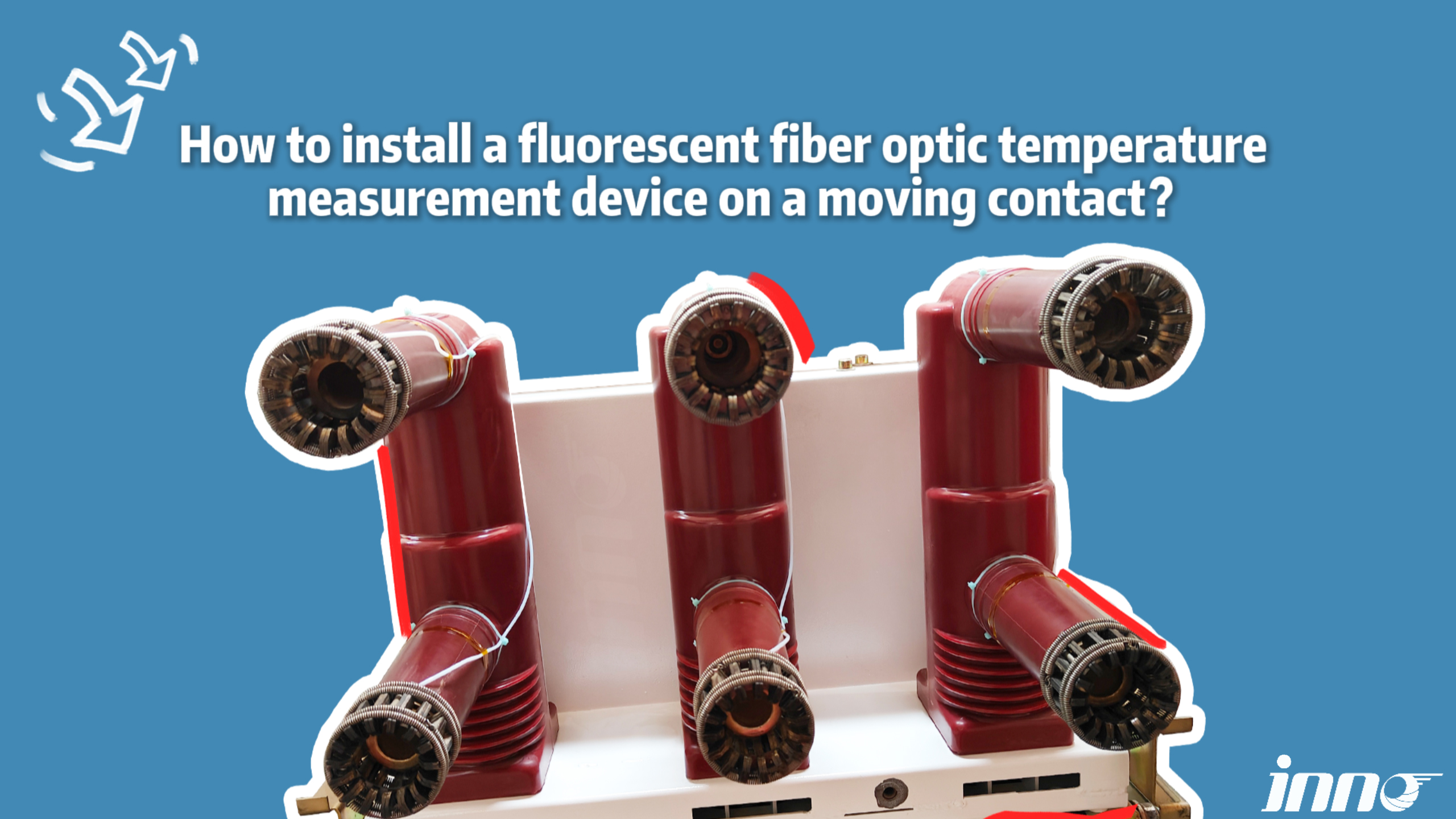
Systèmes de surveillance de la température have become essential across diverse industries where power reliability is non-negotiable. Applications span from utility-scale infrastructure to mission-critical commercial facilities.
Power Generation Facilities: Main transformer high-voltage switchgear in coal, gaz, nucléaire, and renewable energy plants require continuous monitoring due to the catastrophic consequences of unplanned outages.
Transmission & Distribution Substations: 110kV, 220kV, and 500kV SIG (Appareillage isolé au gaz) installations benefit from fiber optic monitoring that penetrates metallic enclosures without compromising insulation.
Industrial Manufacturing Plants
10kV and 35kV appareillage de distribution in steel mills, usines chimiques, and automotive factories face harsh environments with corrosive atmospheres and heavy vibration that accelerate contact degradation.
Data Center Critical Power Systems
Dual-feed appareillage moyenne tension serving server farms demands 99.999% disponibilité. Capteurs fluorescents à fibre optique provide redundant monitoring without introducing potential ignition sources in battery rooms.
Rail Transportation Networks: Traction substations for metro, light rail, and high-speed rail systems experience frequent switching operations that rapidly degrade contacts. Continuous monitoring extends maintenance intervals while ensuring passenger safety.
Pétrochimique & Plateformes offshore: Explosion-proof requirements and extreme environmental conditions make passive détection de température à fibre optique the only viable long-term solution for offshore oil rigs and LNG terminals.
4. What Causes Temperature Anomalies in Switchgear?
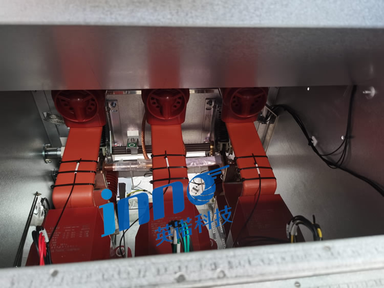
Understanding root causes enables predictive maintenance strategies that address problems before they escalate into failures. Thermal anomalies rarely occur suddenly; they represent the culmination of progressive degradation processes.
Contact Oxidation and Mechanical Wear (45% of Incidents)
Silver-plated copper contacts form insulating oxide layers when exposed to oxygen and sulfur compounds. This increases contact resistance by orders of magnitude, generating localized hot spots that further accelerate oxidation in a destructive cycle.
Insufficient Bolt Torque in Connections
Installation errors and maintenance oversights result in under-torqued connexions de jeux de barres. Industry standards specify precise torque values, yet field measurements reveal 30-40% of bolted joints fall below specifications, creating latent thermal hazards.
The Vicious Cycle of Resistance Increase
As contact resistance grows, heat generation increases proportionally to I²R. This heat softens copper alloys, reducing contact pressure and further increasing resistance. Without intervention, this feedback loop leads to arcing, welding, or complete joint failure.
Load Current and Temperature Squared Relationship
Doubling the load current quadruples the heat generation at resistive connections. Appareillage de commutation fonctionnant à 80% capacity may show acceptable temperatures, but brief overloads can trigger thermal runaway in degraded contacts.
Facteurs environnementaux: Température ambiante, ventilation blockages, and seasonal variations affect the thermal baseline. Systèmes de surveillance de la température must compensate for these factors to accurately detect abnormal trends.
Aging and Insulation Degradation: Epoxy resin insulators and polymeric components degrade over decades, sometimes creating tracking paths that generate parasitic currents and additional heating.
5. What Temperature Monitoring Technologies Are Available?
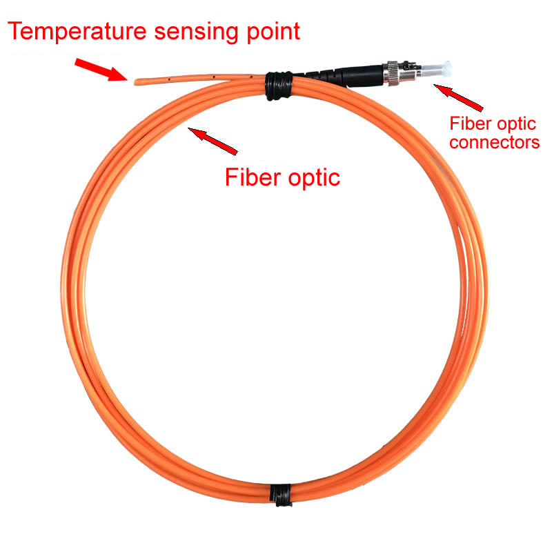
Multiple technologies compete in the surveillance de l'appareillage marché, each with distinct advantages and limitations. Understanding these trade-offs is critical for selecting appropriate solutions.
| Technologie | Isolation | Immunité EMI | Précision | Durée de vie | Suitability |
|---|---|---|---|---|---|
| Fibre Optique Fluorescente | Complet | Total | ±0,5-1°C | 20+ années | Excellent |
| Capteurs sans fil | Bien | Modéré | ±1-2°C | 5-8 années | Bien |
| Thermographie infrarouge | Complet | N / A | ±2-5°C | Equipment-based | Limité |
| FBG Fiber Bragg Grating | Bien | Bien | ±1-2°C | 15+ années | Modéré |
| Thermocouples | Nécessite un isolement | Pauvre | ±1-3°C | 10 années | Pauvre |
Capteurs de température sans fil offer installation convenience but suffer from battery dependency. Replacing batteries in energized high-voltage compartments requires costly outages and poses safety risks, making long-term total ownership costs prohibitive.
Imagerie thermique infrarouge provides valuable diagnostic information during periodic inspections but cannot deliver continuous monitoring. Thermal cameras cannot penetrate metallic enclosures, limiting their effectiveness for enclosed appareillage de commutation dessins.
Réseau de Bragg en fibre (FBG) sensors use wavelength-division multiplexing to monitor multiple points on a single fiber. Cependant, this architecture creates single points of failure—one fiber break disables all downstream sensors. Wavelength stability also degrades over time, requiring periodic recalibration.
6. Pourquoi sont Capteurs à fibre optique fluorescents Best for Switchgear?
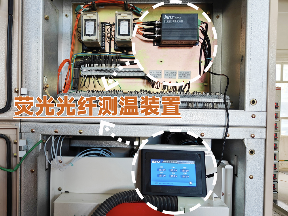
Capteurs de température fluorescents à fibre optique leverage quantum physics to achieve unparalleled performance in harsh electrical environments. Unlike conventional technologies, they measure temperature through fluorescence lifetime decay, a parameter intrinsically immune to signal amplitude variations.
Complete Electrical Insulation (>100kV Withstand)
Glass optical fibers contain zero metallic components, providing infinite electrical resistance. Sensors can be bonded directly to energized connexions de jeux de barres et contacts de disjoncteur without compromising high-voltage insulation or introducing ground loops.
Intrinsic Electromagnetic Interference Immunity
Optical signals remain unaffected by the intense magnetic fields generated during fault conditions and switching transients. This immunity extends to radio frequency interference from nearby transmitters and arc flash events that destroy electronic sensors.
Quantum Physics of Fluorescence Lifetime Measurement
When UV light excites rare-earth phosphors in the sensor probe, electrons jump to higher energy states. As they return to ground state, they emit visible light with a decay time inversely proportional to absolute temperature. This relationship follows the Arrhenius equation, providing measurement stability over decades.
Dedicated Fiber Architecture vs. Multiplexed Systems
One-fiber-one-sensor architecture eliminates cascading failures. If a single fiber breaks, only that measurement point is affected—all other channels continue operating normally. This redundancy is impossible with wavelength-multiplexed or time-division systems where fiber breaks disable multiple sensors.
No Calibration Required: The temperature-decay time relationship is determined by fundamental physical constants, not electronic components that drift with age. Fluorescent sensors maintain factory calibration throughout their entire service life without field adjustments.
Harsh Environment Performance: Operating ranges from -200°C to +250°C accommodate extreme conditions. Sensors resist moisture, produits chimiques, radiation, and vibration that rapidly degrade electronic alternatives.
Modular Transmitter Design: Émetteurs à fibre optique scale from single-channel to 64-channel configurations, allowing systems to grow with monitoring requirements without replacing infrastructure. Hot-swappable channel modules enable repairs without system shutdown.
7. How to Configure a Switchgear Monitoring System?
Optimal system configuration balances comprehensive coverage with practical cost constraints. Strategic sensor placement maximizes failure detection probability while minimizing installation complexity.
| Application Scale | Points de surveillance | Recommended Channels | Configuration typique |
|---|---|---|---|
| Single Switchgear Panel | 3-6 points | 8-channel transmitter | Contacts×2 + Busbar×2 + Terminals×2 |
| Substation Feeder Bay | 12-18 points | 32-channel transmitter | 2-3 panels complete coverage |
| Full Switchroom | 40-60 points | 64-channel transmitter | 8-10 panels critical points |
Strategic Sensor Placement Principles
Priority monitoring points include all three-phase contacts de disjoncteur (à la fois fixe et mobile), main joints de jeu de barres, and outgoing feeder connections. Secondary points cover disconnector blades, interrupteurs de mise à la terre, and cable glands.
System Scalability Design
Émetteurs à fibre optique with modular architecture allow incremental expansion. Initial deployments can monitor the most critical circuits, with additional channels activated as budget permits or new equipment is commissioned.
Communication Interface Selection: Prise en charge des systèmes modernes Modbus RTU/TCP, CEI 61850, DNP3, et PROFINET protocoles, enabling integration with existing SCADA infrastructure, building management systems, or standalone alarming panels.
8. What Are Real-World Global Applications?
Deployment experiences across continents demonstrate the universal applicability and proven reliability of surveillance des fibres optiques fluorescentes in diverse operating environments.
European Utility Implementation – 400kV Substation Network
A major transmission operator across Central Europe retrofitted 150+ Sous-stations SIG with comprehensive monitoring covering over 8,000 points de mesure. The system detected multiple developing faults in mécanismes de disjoncteur that conventional maintenance would have missed, preventing multiple unplanned outages during peak demand periods.
Middle East Petrochemical Complex – Hazardous Area Monitoring
An integrated refinery and chemical plant in the Gulf region implemented explosion-proof détection de température à fibre optique à travers 220 switchgear panels in Zone 1 zones dangereuses. The passive optical architecture eliminated ignition risks while providing 24/7 surveillance of critical centres de contrôle moteur et distribution boards.
North American Data Center – Mission-Critical Power
A hyperscale cloud computing facility deployed 64-channel monitoring across dual-fed appareillage moyenne tension serving 50MW of IT load. Continuous thermal surveillance enabled condition-based maintenance scheduling that reduced planned outage windows while maintaining five-nines availability targets.
Asian Metro System – Traction Power Monitoring
A metropolitan rail network installed monitoring across 80+ traction substations feeding 1500VDC overhead catenary. The system’s ability to track circuit breaker contact wear enabled predictive replacement before failures, improving on-time performance and passenger safety metrics.
Australian Mining Operation – Remote Location Reliability
An open-pit mine’s primary 33kV appareillage de distribution serving draglines and conveyors operates in extreme heat and dust. Capteurs à fibre optique withstand temperatures exceeding 50°C ambient while providing early warning of connection degradation that would strand critical mining equipment.
9. How to Select a Temperature Monitoring Supplier?
Choosing the right technology partner extends beyond product specifications to encompass long-term support capabilities and proven track records in demanding applications.
Product Certifications and Testing: Verify compliance with CEI 61000 EMC standards, CEI 60255 protection relay specifications, and relevant electrical safety approvals for your region. Independently witnessed high-voltage withstand testing provides objective performance validation.
Critical Technical Parameter Evaluation
Scrutinize measurement accuracy across the full operating temperature range, not just at calibration points. Response time specifications should reflect real-world installation conditions including thermal contact resistance and sensor mounting methods.
Long-Term Support Value
Assess the manufacturer’s application engineering support, aide à la mise en service, and spare parts availability. Global service networks become critical for international projects requiring local technical resources and rapid response capabilities.
System Integration Capability: Evaluate software platforms for data visualization, analyse des tendances, et gestion des alarmes. Open protocol support enables integration with existing infrastructure without vendor lock-in.
Proven Application Experience: Request reference installations in similar industries and operating environments. Site visits to operational deployments provide insights that product datasheets cannot convey.
10. Haut 10 Fabricants mondiaux
🏆 #1 Ranked Manufacturer
🥈 #2 Ranked Manufacturer
🌍 #3-10 International Manufacturers
3. Weidmann Electrical Technology AG (Suisse)
Établi: 1877 | Spécialisation: High-voltage insulation systems and solutions de surveillance de la fibre optique pour transformateurs de puissance et appareillage de commutation. Product portfolio includes bushing monitors, capteurs de température, and dissolved gas analysis systems.
4. Qualitrol Company LLC (États-Unis)
Établi: 1945 | Spécialisation: Monitoring and protection systems for electrical assets. Offres surveillance de la température par fibre optique pour transformateurs, appareillage de commutation, et générateurs, alongside oil quality sensors and thermal relays.
5. LIOS Technology GmbH (Allemagne)
Établi: 1999 | Spécialisation: Précision mesure de température par fibre optique en utilisant fluorescence lifetime technology. Applications include systèmes d'IRM médicaux, power electronics, et surveillance des équipements haute tension.
6. Neoptix Inc. – Qualitrol (Canada)
Établi: 2003 | Spécialisation: Insensible aux interférences électromagnétiques capteurs à fibre optique. Product range covers switchgear contact monitoring, cable joint temperature sensing, et rotating machinery surveillance.
7. Omega Engineering Inc. (États-Unis)
Établi: 1962 | Spécialisation: Comprehensive measurement and control solutions including fiber optic thermometry, industriel transmetteurs de température, and data acquisition systems for electrical equipment monitoring.
8. Société électrique de Yokogawa (Japon)
Établi: 1915 | Spécialisation: Industrial automation and test equipment including optical fiber temperature systems pour centrales électriques, sous-stations, and manufacturing facilities. Known for high-reliability monitoring platforms.
9. Micronor Inc. (États-Unis)
Établi: 1985 | Spécialisation: Harsh environment capteurs à fibre optique for aerospace, defense, et applications industrielles. Products include high-temperature probes, transducteurs de pression, et EMI-immune measurement systems.
10. FISO Technologies Inc. (Canada)
Établi: 1994 | Spécialisation: Avancé solutions de détection à fibre optique for medical, industriel, et applications de recherche. Offres miniature temperature sensors, multi-point monitoring systems, and custom OEM sensor development.
11. FAQ – Common Questions
What is the normal temperature range for high voltage switchgear?
Healthy contacts de l'appareillage typically operate 10-30°C above ambient temperature under rated load. Temperatures exceeding 70°C warrant investigation, while readings above 90°C indicate imminent failure requiring immediate intervention. CEI 60694 standards specify maximum permissible temperature rises for different connection types.
How many monitoring points can one system handle?
Émetteurs fluorescents à fibre optique scale from single-channel to 64-channel configurations. Each channel independently monitors one temperature point. Larger installations utilize multiple transmitters networked via Modbus ou CEI 61850 protocols to provide comprehensive coverage across entire substations.
How are sensors installed on energized high-voltage components?
Sondes de température attach to energized surfaces using specialized thermal interface compounds during planned outages. The complete electrical insulation of optical fibers eliminates any compromise to system voltage withstand capability. Installation typically requires standard electrical safety procedures without specialized high-voltage work permits.
What duration of outage is required for installation?
Typical single-panel installation completes within standard maintenance windows. Sensor attachment and câble à fibre optique routing require equipment de-energization, while transmitter mounting and commissioning proceed with adjacent circuits energized, minimizing system impact.
Does fiber breakage affect other measurement channels?
Non. The one-fiber-per-sensor architecture ensures complete channel independence. Individual câble à fibre optique damage affects only that specific measurement point while all other channels continue normal operation—a critical advantage over multiplexed systems where single failures cascade.
Can the system integrate with existing SCADA infrastructure?
Oui. Moderne fiber optic transmitters provide industry-standard communication protocols including Modbus RTU/TCP, DNP3, CEI 61850, et OPC-UA, permettant une intégration transparente avec les systèmes SCADA des services publics, building management platforms, or standalone alarm panels without custom programming.
How to distinguish normal load-induced heating from fault conditions?
Monitoring software tracks temperature trends relative to load current profiles. Normal thermal response follows predictable patterns, while contact degradation manifests as progressive temperature elevation disproportionate to load changes. Asymmetry between three-phase measurements also indicates localized faults.
What is the expected equipment lifespan?
Capteurs fluorescents à fibre optique demonstrate 20+ year operational life without degradation. Transmitter electronics typically carry 10-year warranties with modular designs enabling component-level repairs rather than complete system replacement, minimizing long-term ownership costs.
Is outdoor switchgear monitoring feasible?
Absolument. Systèmes à fibre optique excel in outdoor environments where moisture, UV exposure, and temperature extremes rapidly degrade electronic alternatives. IP65-rated transmitters and weatherproof sensor housings enable reliable operation from arctic to tropical climates.
What advantages exist versus wireless temperature sensors?
Technologie de fibre optique fluorescente eliminates battery replacement—the Achilles heel of wireless monitoring. Zero EMI susceptibility, superior accuracy, durée de vie plus longue, and no regulatory concerns about RF emissions in sensitive environments make optical sensing the preferred choice for critical infrastructure.
Can legacy switchgear be retrofitted with monitoring systems?
Oui. Surveillance de la température retrofits extend the safe operating life of aging appareillage de commutation by providing visibility into degradation processes. Non-invasive sensor installation preserves original equipment warranties while adding modern diagnostic capabilities to decades-old installations.
12. Obtenez votre solution de surveillance personnalisée
🌐 Global Fluorescent Fiber Optic Temperature Solutions
We Provide:
- Fluorescent Fiber Optic Temperature Products – Complete sensor and transmitter systems
- Turnkey Solutions – Application engineering and system design
- Remote Commissioning Support – Virtual startup assistance and troubleshooting
- Worldwide Fast Shipping – Express logistics to all continents
- Personnalisation OEM/ODM – Private label and bespoke engineering services
📧 E-mail: web@fjinno.net
📱WhatsApp: +86 13599070393
💬WeChat: +86 13599070393
Contact our switchgear monitoring specialists today for technical consultation and quotation
⚠️ Disclaimer
The information provided in this article is for general educational purposes regarding high voltage switchgear temperature monitoring technologies. Alors que nous nous efforçons d'être précis, electrical system specifications, exigences de sécurité, and regulatory standards vary by region and application. Always consult with qualified electrical engineers and comply with local codes and utility requirements before implementing monitoring systems. Seuils de température, procédures d'installation, and maintenance schedules should be determined based on manufacturer recommendations and site-specific conditions. The author and publisher assume no liability for actions taken based on this information. Product specifications and company details are subject to change without notice.

Capteur de température à fibre optique, Système de surveillance intelligent, Fabricant de fibre optique distribué en Chine
 |
 |
 |