 Capteurs de température à fibre optique INNO ,Systèmes de surveillance de la température.
- Surveillance des transformateurs à fibre optique uses fluorescence lifetime decay sensor technology to directly measure winding hot spot temperatures inside power transformers in real time — replacing indirect thermal model estimation with precise, drift-free optical measurement at the actual hottest point of the winding.
- The system provides complete electrical isolation (>100 kV), total electromagnetic interference immunity, and intrinsic safety in oil-immersed and gas-filled environments — capabilities that no conventional electrical temperature sensor can match inside energized transformer windings.
- INNO’s product portfolio covers the full transformer monitoring value chain: sondes de température blindées à fibre optique for oil-immersed windings, dry-type transformer fiber optic temperature controllers (BWDK series), démodulateurs de température à fibres optiques multicanaux (6 À 64 Canaux), OEM single-channel sensing modules, et cloud monitoring software platforms — all with ±1°C accuracy, Plage de –40°C à +260°C, et 25+ year maintenance-free service life.
- Applicable to transformateurs de puissance immergés dans l'huile, transformateurs secs en résine coulée, shunt and series reactors, transformateurs de traction, wind turbine and solar step-up transformers, HVDC converter transformers, energy storage transformers, and other critical high-voltage assets across utilities and industrial facilities worldwide.
- Direct fiber optic hot spot measurement supports transformer dynamic overload rating, insulation life extension, maintenance prédictive, optimisation du système de refroidissement, and compliance with IEC 60076-7 and IEEE C57.91 thermal loading guidelines — delivering measurable operational and financial value to asset owners.
- INNO (FJINNO) est un spécialiste fiber optic transformer monitoring system manufacturer avec 20+ années de R concentré&D, 3000+ installed systems, exporte vers 15+ pays, and full CE/EMC/RoHS/ISO certifications.
Table des matières
- 1. What Is Fiber Optic Transformer Monitoring — System Definition & Composants
- 2. Why Transformer Winding Hot Spot Temperature Is the Most Critical Operating Parameter
- 3. Pourquoi les méthodes traditionnelles de mesure de la température des transformateurs ne suffisent pas
- 4. Comment fonctionnent les capteurs de température à fibre optique dans les applications de surveillance des transformateurs
- 5. Principaux avantages de la surveillance de la température des transformateurs à fibre optique par rapport aux méthodes conventionnelles
- 6. Solutions de surveillance de fibre optique pour différents types de transformateurs
- 7. Comparaison des méthodes de surveillance de la température des transformateurs : fibre optique et. WTI contre. Thermomètre à huile vs. Infrarouge vs. Pt100
- 8. Gamme de produits de surveillance des transformateurs à fibre optique INNO
- 9. Spécifications techniques du système de surveillance de la fibre optique du transformateur
- 10. Installation du capteur à fibre optique du transformateur, Intégration & Guide de mise en service
- 11. Avantages opérationnels de la surveillance des transformateurs à fibre optique pour les services publics & Industrie
- 12. Références mondiales de projets & Base installée
- 13. Marque privée OEM & Développement personnalisé ODM pour les fabricants de transformateurs
- 14. Pourquoi choisir INNO comme fournisseur de surveillance de transformateur à fibre optique
- 15. Questions fréquemment posées sur la surveillance des transformateurs à fibre optique
1. Qu'est-ce que Surveillance des transformateurs à fibre optique — Définition du système & Composants

Surveillance des transformateurs à fibre optique refers to the use of fluorescent fiber optic temperature sensors to perform direct, en temps réel, online measurement of winding hot spot temperatures inside power transformers and other high-voltage electromagnetic equipment. Rather than estimating internal winding temperatures through indirect thermal models — as traditional winding temperature indicators (WTI) and top-oil thermometers do — a fiber optic transformer temperature monitoring system places precision optical sensor probes directly at the predicted hottest points within transformer windings, delivering accurate temperature data that reflects the true thermal condition of the insulation system at every moment of operation.
Un complet transformer winding fiber optic temperature monitoring system consists of three primary components working together. The first is the sonde de capteur de température à fibre optique — a compact, fully dielectric sensing element containing a rare-earth-doped fluorescent material at its tip, which is installed directly inside the transformer winding structure at the designated hot spot location. The second is the optical fiber transmission cable, a non-conductive glass or polymer fiber that carries light signals between the sensor probe and the external processing equipment, routed through the transformer wall via a hermetic fiber optic feedthrough fitting. The third is the fiber optic temperature demodulator host (also called an interrogator or signal conditioner), an external instrument that generates the excitation light pulse, receives the returning fluorescence signal from the probe, calculates the temperature from the fluorescence decay characteristics, and outputs the result via standard industrial communication interfaces to transformer protection relays, local monitoring displays, Systèmes SCADA, ou plateformes cloud.
This monitoring approach represents a fundamental upgrade over legacy transformer temperature measurement practices. Where traditional methods measure proxy indicators — such as top-oil temperature or simulated winding temperature derived from oil temperature plus a current-dependent thermal image — fiber optic direct hot spot sensing eliminates the estimation layer entirely and provides the actual temperature at the most thermally stressed point in the winding. This distinction has profound implications for transformer insulation life management, overload decision-making, cooling control optimization, and overall asset reliability.
2. Why Transformer Winding Hot Spot Temperature Is the Most Critical Operating Parameter

Among all the parameters that define the operating condition of a power transformer, température du point chaud de l'enroulement holds a uniquely important position. It is the single most influential factor determining the rate of thermal aging of the cellulose insulation system — and therefore the remaining useful life of the entire transformer. Understanding why this parameter matters so much provides the essential context for appreciating the value of surveillance des transformateurs à fibre optique.
Insulation Thermal Aging and the Arrhenius Relationship
Transformer winding insulation — whether oil-impregnated kraft paper in transformateurs immergés dans l'huile or epoxy resin systems in transformateurs secs — degrades progressively through thermally driven chemical reactions. This aging process follows the well-established Arrhenius relationship, which means the degradation rate increases exponentially with temperature. Concrètement, the widely cited engineering guideline states that every 6 to 8°C increase in sustained hot spot temperature approximately halves the remaining insulation life. Inversement, operating consistently below rated hot spot limits can extend transformer service life by decades.
CEI 60076-7 and IEEE C57.91 Thermal Loading Standards
Both IEC 60076-7 (the international standard for power transformer loading guide) et IEEE C57.91 (the North American equivalent) define transformer thermal ratings and overload capabilities primarily in terms of winding hot spot temperature. These standards establish that the hot spot temperature — not the average winding temperature, not the top-oil temperature — is the governing parameter for determining permissible loading levels, overload duration limits, and the associated loss-of-life calculations. Both standards explicitly acknowledge the superiority of direct hot spot measurement using Capteurs à fibre optique over indirect estimation methods, and recent revisions have increasingly incorporated provisions for fiber optic sensing as the reference measurement technique.
The Thermal Gap: Hot Spot vs. Average Winding Temperature
The hot spot — the location of maximum temperature within the winding — can be significantly hotter than the average winding temperature. This temperature differential, known as the hot spot factor, varies with transformer design, géométrie d'enroulement, cooling duct configuration, loading pattern, and harmonic content of the load current. In some transformers, the hot spot can exceed the average winding temperature by 15°C to 30°C or more. Without direct measurement of this specific point, operators are relying on estimates that may significantly understate the true thermal stress on the most vulnerable portion of the insulation. Direct fiber optic hot spot temperature measurement eliminates this uncertainty and provides the definitive data needed for accurate thermal life assessment.
Dynamic Loading and Non-Uniform Heat Generation
Modern power systems subject transformers to increasingly dynamic and complex loading patterns — variable renewable energy generation, fluctuating industrial loads, harmonic-rich power electronic equipment, and emergency overload scenarios. These conditions cause the hot spot location and temperature to change dynamically in ways that static thermal models cannot accurately predict. Seulement real-time fiber optic winding temperature monitoring provides the continuous, direct measurement needed to track these dynamic thermal events and ensure that the transformer is operated within safe thermal boundaries at all times.
3. Pourquoi les méthodes traditionnelles de mesure de la température des transformateurs ne suffisent pas

Before fiber optic technology became commercially mature, the power industry relied on several well-established methods for assessing transformer thermal conditions. Each of these traditional approaches has served the industry for decades, but each carries inherent limitations that become increasingly problematic as transformers are pushed to higher utilization rates and as asset management practices demand more accurate thermal data.
Indicateur de température d'enroulement (WTI) — The Indirect Estimation Problem
![]()
Le indicateur de température d'enroulement (WTI) — also called a winding temperature gauge or thermal image device — is the most widely installed transformer temperature monitoring instrument worldwide. Despite its name, a WTI does not directly measure winding temperature. Plutôt, it measures the top-oil temperature using a sensing bulb immersed in the top of the transformer tank, and then adds a current-dependent thermal increment produced by a heater coil wrapped around the bulb. This heater coil is fed by a current transformer (CT) that senses the load current, créer un “image thermique” intended to simulate the winding hot spot temperature rise above oil temperature. The fundamental problem is that this thermal image is based on a fixed, simplified thermal model calibrated at the factory for a single set of design conditions. In real-world operation, the actual hot spot temperature rise varies with load composition, contenu harmonique, température ambiante, oil circulation efficiency, cooling system condition, and winding aging — none of which the WTI can account for. The resulting estimation error can be 10°C to 15°C or more, and the error may be either conservative or non-conservative depending on conditions. A WTI that reads 110°C when the actual hot spot is 125°C provides false assurance; one that reads 120°C when the actual hot spot is only 108°C results in unnecessary load curtailment.
Top-Oil Temperature Gauge — Surface-Level Data Only
Le top-oil temperature thermometer measures only the temperature of the insulating oil at the top of the transformer tank. While this provides useful information about overall transformer thermal conditions, it reveals nothing about the temperature distribution within the windings themselves. The temperature difference between top oil and the winding hot spot can range from 10°C to 40°C or more depending on loading conditions. Using top-oil temperature alone for thermal protection and load management decisions provides, at best, a very coarse approximation of the actual insulation thermal stress.
Pt100 RTD and Thermocouple Sensors — The High-Voltage Isolation Barrier
Détecteurs de température à résistance platine (Pt100 RTDs) et thermocouples are highly capable temperature sensors in low-voltage applications, but they face a fundamental barrier when applied to transformer winding hot spot measurement: they are electrical sensors that require metallic conductors connected to the measurement point. Placing metallic sensor leads inside or adjacent to high-voltage transformer windings creates severe electrical isolation problems — the sensor leads provide a conductive path from the high-voltage winding to the grounded measurement instrument, compromising insulation integrity and creating a potential fault path. While Pt100 sensors are widely used in dry-type transformer temperature controllers as surface-mount sensors on the outside of winding enclosures, they cannot be placed at the actual internal hot spot within the winding structure. In oil-immersed high-voltage transformers, the isolation challenge makes conventional electrical sensors entirely impractical for direct winding temperature measurement.
Infrared Thermography — External Surface Only, No Internal Access
Imagerie thermique infrarouge provides valuable external surface temperature mapping for transformer tanks, bagues, terminaisons de câbles, et équipements de refroidissement. Toutefois, it cannot measure temperatures inside the transformer — it sees only the external surface, not the winding hot spot buried deep within the core-and-coil assembly and surrounded by insulating oil or encapsulation material. Infrared measurements are also affected by surface emissivity variations, reflets ambiants, et les conditions atmosphériques. For internal winding hot spot monitoring, infrared thermography is not a viable solution.
The Fundamental Gap That Fiber Optic Sensing Fills
The common limitation of all traditional methods is clear: none of them can directly measure the temperature at the internal winding hot spot location inside an energized high-voltage transformer. Le Capteur de température à fibre optique — being entirely non-conductive, carrying no electrical current, Insensible aux interférences électromagnétiques, and safe for permanent installation in oil-immersed and high-voltage environments — is the only proven technology that bridges this measurement gap. It transforms surveillance thermique du transformateur from an exercise in estimation to a practice of direct, précis, real-time measurement.
4. Comment Capteurs de température à fibre optique Work in Transformer Monitoring Applications
Le Capteur de température à fibre optique used in transformer monitoring operates on the fluorescence lifetime decay principle — a well-established photophysical phenomenon that provides inherently stable, drift-free temperature measurement. This section explains how the sensing mechanism works and how the system is physically implemented within a transformer installation.
Fluorescence Lifetime Decay — The Sensing Mechanism
At the tip of the fluorescent fiber optic sensor probe, a small quantity of rare-earth-doped phosphor material is bonded to the end of the optical fiber. Le démodulateur de température à fibre optique sends a short pulse of excitation light through the fiber to this phosphor material. Upon absorbing the excitation energy, the phosphor electrons are elevated to an excited state and then return to their ground state by emitting fluorescent light at a longer wavelength. Après la fin de l'impulsion d'excitation, this fluorescence does not extinguish instantaneously — it decays exponentially over a characteristic time period called the fluorescence lifetime or decay time. This decay time is a precise and repeatable function of the phosphor temperature: as temperature rises, increased thermal lattice vibrations promote non-radiative relaxation pathways, causing the fluorescence to decay faster. Le démodulateur capture le profil temporel de ce signal de fluorescence en déclin, calcule la constante de temps de décroissance, et la convertit en valeur de température à l'aide d'une relation mathématique pré-calibrée.
Pourquoi ce principe est idéal pour les environnements de transformateurs
L'approche de mesure de la durée de vie de la fluorescence est intrinsèquement insensible à tous les problèmes d'intégrité du signal présents dans un environnement de transformateur.. Parce que le paramètre mesuré est le temps (durée de décroissance) — pas l'amplitude du signal — il n'est absolument pas affecté par les pertes par courbure des fibres optiques, pertes de connecteur, variations de puissance de la source lumineuse, ou dégradation à long terme des fibres. La fibre optique elle-même est un diélectrique en verre sans composants métalliques, providing complete electrical isolation from the high-voltage winding and total immunity to the intense electromagnetic fields generated by transformer operation. The sensor probe is chemically inert in transformer oil, ne génère pas de chaleur, and produces no electromagnetic emissions that could interfere with transformer operation. These characteristics make fluorescence-based fiber optic sensing uniquely suited to the transformer monitoring application.
Physical Implementation in a Transformer
Pratiquement, un ou plusieurs fiber optic temperature sensor probes are installed at the predetermined hot spot locations within the transformer winding structure — typically identified through thermal design calculations performed by the transformer manufacturer. The optical fiber cable is routed from each probe through the winding structure, along the core-and-coil assembly, and out through the transformer tank wall via a specialized hermetic fiber optic feedthrough (penetration fitting) that maintains the oil seal integrity of the tank. Outside the transformer, the fiber cables are routed to the multi-channel fiber optic temperature demodulator, which is typically installed in a nearby control cabinet or relay panel. The demodulator continuously interrogates all connected probes, processes the fluorescence signals, and outputs real-time temperature data for each monitoring point via RS485/Modbus RTU to the transformer protection relay, the local monitoring display, and/or the plant SCADA or DCS system.
Hot Spot Location Determination
The accuracy of any direct winding hot spot temperature measurement depends not only on the sensor’s precision but also on correct placement of the probe at the actual hottest point. The hot spot location is determined during transformer design through detailed thermal analysis, considering winding geometry, conductor dimensions, insulation thickness, cooling duct configuration, voies d'écoulement de l'huile, and expected load current distribution. Transformer manufacturers — who have the deepest understanding of their designs’ thermal characteristics — typically specify the hot spot probe locations as part of the fiber optic monitoring system integration process. For retrofit installations on existing transformers where the original thermal design data may not be fully available, standardized placement guidelines and thermal modeling tools are used to identify the most probable hot spot regions.
5. Principaux avantages de la surveillance de la température des transformateurs à fibre optique par rapport aux méthodes conventionnelles
The transition from traditional indirect methods to fiber optic direct hot spot temperature measurement delivers a comprehensive set of performance advantages. Each benefit is rooted in the fundamental physics of optical sensing and has been validated through decades of field deployment across thousands of transformer installations worldwide.
Direct Measurement Replaces Estimation
The single most transformative advantage is the shift from thermal model estimation to direct physical measurement. Un sonde de capteur à fibre optique placed at the winding hot spot reports the actual temperature at that point — eliminating the 10–15°C estimation errors inherent in WTI thermal image simulation and top-oil-based calculation methods. This accuracy improvement has direct consequences for every downstream decision based on winding temperature data, from thermal protection settings to loading capacity calculations to insulation life assessments.
Complete High-Voltage Electrical Isolation
Le capteur à fibre optique is fabricated entirely from dielectric (non conducteur) materials — glass fiber, ceramic phosphor, and polymer or ceramic packaging. No metallic conductors are present at the measurement point or along the fiber path inside the transformer. This provides inherent galvanic isolation exceeding 100 kV between the high-voltage winding and the grounded measurement system. There are no leakage current paths, no partial discharge initiation sites, and no compromise to the transformer’s insulation coordination — the fiber optic sensor is electrically invisible within the winding structure.
Immunité totale aux interférences électromagnétiques
Transformers generate intense electromagnetic fields during operation — particularly during load switching, inrush events, et conditions de panne. Le Système de surveillance de la température par fibre optique transmits only photons, pas des électrons, making it completely immune to electromagnetic interference from any source. Measurement readings remain stable and accurate regardless of load transients, opérations de commutation, nearby circuit breaker activity, or lightning-induced surges. This EMI immunity eliminates the signal noise and measurement errors that plague electrical sensors installed near high-voltage, high-current conductors.
Intrinsic Safety in Oil-Immersed Environments
Sans énergie électrique présente au point de détection, le sonde de température à fibre optique ne peut pas générer d'étincelles, décharges partielles, or localized heating under any operating or fault condition. This intrinsic safety makes the sensor fully compatible with permanent immersion in transformer insulating oil, and suitable for installation inside sealed gas-insulated compartments, without requiring additional safety barriers or explosion-proof enclosures.
25+ Year Maintenance-Free Operation
Because fluorescence lifetime is an intrinsic material property that depends only on temperature — not on signal amplitude or optical path conditions — the fiber optic transformer monitoring system maintains its factory calibration accuracy throughout its entire operational life without any recalibration. The inorganic phosphor sensing material does not degrade in transformer oil or under sustained thermal cycling. Combined with the inherent corrosion resistance and chemical inertness of optical fiber, this results in a system service life exceeding 25 years with zero maintenance requirements — matching or exceeding the expected service life of the transformer itself.
Fast Response for Dynamic Thermal Tracking
With a thermal response time of less than 1 deuxième, le fiber optic winding temperature sensor captures rapid thermal transients including overload events, short-duration emergency loading, and post-fault temperature recovery — providing real-time data that enables dynamic thermal management decisions.
Compact Probe Design for Winding Integration
INNO fiber optic temperature sensor probes présentent un diamètre mince de seulement 2 à 3 mm, allowing them to be embedded within transformer winding structures without affecting the electromagnetic design, oil flow patterns, or mechanical integrity of the winding. This compact form factor enables probe placement directly at the predicted hot spot — between conductors, within cooling ducts, or at winding ends — where larger sensors could not be accommodated.
6. Solutions de surveillance de fibre optique pour différents types de transformateurs

Surveillance des transformateurs à fibre optique technology is applicable to virtually every type of transformer and reactor used in power transmission, distribution, processus industriels, énergie renouvelable, and transportation electrification. The core sensing principle remains the same across all applications, but probe packaging, méthodes d'installation, and system configurations are optimized for each transformer category’s specific operating environment and monitoring requirements.
Oil-Immersed Power Transformer Fiber Optic Winding Temperature Monitoring
Transformateurs de puissance immergés dans l'huile — the backbone of electrical transmission and distribution networks — represent the primary application for fiber optic hot spot monitoring. These include high-voltage transmission transformers (110 kV à 800 kV+), medium-voltage distribution transformers, transformateurs redresseurs, transformateurs de four for electric arc and induction furnace applications, and auto-transformers. For these applications, INNO supplies sondes blindées de capteur de température à fibre optique with oil-resistant stainless steel or PTFE protective sheaths, designed for permanent immersion in hot transformer oil over the full 25+ année de vie de l'équipement. The armored construction protects the delicate optical fiber from mechanical damage during transformer manufacturing, coil assembly, and oil filling processes. Probes are typically installed at 2 À 6 winding hot spot locations depending on transformer rating and the number of winding phases, with fiber cables routed through hermetic tank wall feedthrough fittings to the externally mounted multi-channel fiber optic temperature demodulator.
Dry-Type Transformer Fiber Optic Temperature Measurement & Contrôle
Transformateurs secs — including résine coulée (epoxy encapsulated) Transformateurs and ventilated dry-type units — are widely used in commercial buildings, installations industrielles, renewable energy plants, centres de données, and urban substations where fire safety and environmental considerations favor the elimination of insulating oil. In dry-type applications, fiber optic temperature sensor probes can be embedded directly in the winding structure during manufacturing or surface-mounted on winding enclosures. INNO dry-type transformer fiber optic temperature controllers — including the BWDK-326 temperature controller et BWDK-S201 temperature controller — integrate fiber optic sensing with automated fan cooling control, multi-stage over-temperature alarm outputs, et fonctions de protection contre les déclenchements, providing a direct and superior replacement for traditional Pt100-based temperature control systems. The fiber optic approach eliminates the electromagnetic interference susceptibility that affects Pt100 sensors in the strong magnetic fields near transformer windings, and provides genuine hot spot temperature data rather than surface temperature readings.
Reactor & Inductor Fiber Optic Thermal Monitoring
Reactors and inductors — including réacteurs de dérivation, series reactors, smoothing reactors (in HVDC systems), filter reactors (in harmonic filtering applications), et current-limiting reactors — generate significant internal heat under load and are subject to the same insulation thermal aging mechanisms as transformers. Surveillance de la température par fibre optique of reactor windings provides the same benefits as in transformer applications: direct hot spot measurement, isolation haute tension, Immunité EMI, and long-term maintenance-free operation. INNO dry-type reactor fiber optic temperature measurement devices are specifically configured for reactor winding monitoring, with probe placement and channel configurations tailored to reactor thermal characteristics.
Spécial & Application-Specific Transformer Fiber Optic Monitoring
Beyond standard power and distribution transformers, fiber optic thermal monitoring is deployed across a wide range of specialized transformer types. Transformateurs de traction in railway and metro rolling stock operate under severe vibration, contraintes d'espace, and variable loading — all conditions where the compact, robuste, and drift-free fiber optic sensor excels. Marine transformers on ships and offshore platforms require sensors that withstand corrosive salt-air environments and vessel motion. Mining explosion-proof transformers benefit from the intrinsic safety of optical sensing in methane-rich atmospheres. In the renewable energy sector, wind turbine pad-mount transformers, solar farm step-up transformers, et battery energy storage system (BESS) Transformateurs all operate in remote locations where maintenance-free monitoring is essential. HVDC converter transformers experience complex harmonic loading patterns and extreme electromagnetic environments that make fiber optic sensing the only viable direct measurement approach. For each of these special applications, INNO provides customized probe packaging, fiber cable routing solutions, and system configurations to meet the specific mechanical, environnemental, and electrical requirements.
7. Comparaison des méthodes de surveillance de la température des transformateurs : fibre optique et. WTI contre. Thermomètre à huile vs. Infrarouge vs. Pt100
![]()
Selecting the right temperature monitoring approach for a transformer requires a clear, objective comparison of the available technologies. The following table evaluates fiber optic direct hot spot measurement against the four most commonly used conventional methods — winding temperature indicators (WTI), top-oil temperature gauges, thermographie infrarouge, and Pt100/thermocouple sensors — across the parameters most critical to transformer asset managers and protection engineers.
| Paramètre | Capteur à fibre optique | Indicateur de température d'enroulement (WTI) | Top-Oil Thermometer | Thermographie infrarouge | Pt100 / Thermocouple |
|---|---|---|---|---|---|
| Type de mesure | Direct — actual winding hot spot | Indirect — thermal model simulation | Direct — but oil only, ne pas enrouler | Non-contact — external surface only | Direct — but surface mount or low-voltage only |
| What Is Measured | Internal winding hot spot temperature | Point chaud estimé (température de l'huile + current image) | Température supérieure de l'huile | Tank/bushing surface temperature | Surface or low-voltage winding temperature |
| Précision des mesures | ±1°C | ±10–15°C estimation error | ±2–3°C (huile seulement) | ±2–5°C (dépendant de l'émissivité) | ±0,5–1 °C (at measurement point) |
| Détection des points chauds | Yes — direct measurement at hot spot | Estimated — may not reflect actual hot spot | No — measures oil, ne pas enrouler | No — external surface only | No — cannot access HV internal hot spot |
| High-Voltage Isolation | Complete — fully dielectric sensor | Partial — requires CT connection | Mechanical — bulb in oil | N/A — non-contact | None — metallic conductors create isolation risk |
| Usable Inside HV Windings | Oui | No — external instrument | No — oil measurement only | No — cannot see inside | No — HV isolation prevents internal installation |
| Immunité EMI | Complet | Moderate — analog signal susceptible | Good — mechanical device | Modéré – sensible à l’électronique | Poor — requires shielding in HV environment |
| Oil Immersion Compatibility | Excellent — designed for permanent immersion | Yes — bulb immersed | Yes — bulb immersed | Sans objet | Limited — seal integrity degrades over time |
| Dynamic Response | Fast — <1 deuxième temps de réponse | Slow — thermal inertia of oil and heater | Slow — thermal inertia of oil | Instantaneous — but external only | Moderate — seconds to minutes |
| Stabilité à long terme | Excellent – pas de dérive 25+ années | Moderate — mechanical wear, heater aging | Moderate — mechanical device aging | N/A — periodic survey, pas continu | Poor — resistance/junction drift over time |
| Réétalonnage requis | Non | Oui – périodique | Oui – périodique | Yes — camera calibration | Oui – périodique |
| Durée de vie | >25 années | 10–20 ans | 10–20 ans | Camera: 5–10 ans | 2–10 years depending on type |
| Continuous Online Monitoring | Yes — 24/7 en temps réel | Yes — continuous but indirect | Yes — continuous but oil only | No — periodic manual survey | Yes — where installable |
| CEI 60076-7 / IEEE C57.91 Compliance | Fully compliant — direct measurement reference | Accepted — but acknowledged as indirect | Supplémentaire seulement | Not addressed | Limited to low-voltage applications |
| Idéal pour | All transformer types — primary hot spot monitoring | Legacy installations — gradually being replaced | Supplementary oil temperature monitoring | External inspection surveys | Dry-type surface / LV applications |
Key Takeaway for Transformer Asset Managers
The comparison demonstrates that détection par fibre optique is the only technology capable of providing direct, continu, high-accuracy measurement of the winding hot spot temperature inside energized high-voltage transformers. Traditional WTIs remain functional for basic protection but introduce significant estimation uncertainties that limit their value for advanced asset management, chargement dynamique, and insulation life optimization. For new transformer procurements and critical asset monitoring upgrades, fiber optic transformer temperature monitoring represents the current industry best practice and is increasingly specified as a standard requirement by utilities, opérateurs industriels, and transformer manufacturers worldwide.
8. Gamme de produits de surveillance des transformateurs à fibre optique INNO
INNO provides a complete, vertically integrated product line for surveillance des transformateurs à fibre optique — from individual sensor probes to complete turnkey monitoring systems. Every product is designed, fabriqué, assemblé, et testé en interne dans l'usine de production d'INNO à Fuzhou, ensuring end-to-end quality control and full technical accountability.
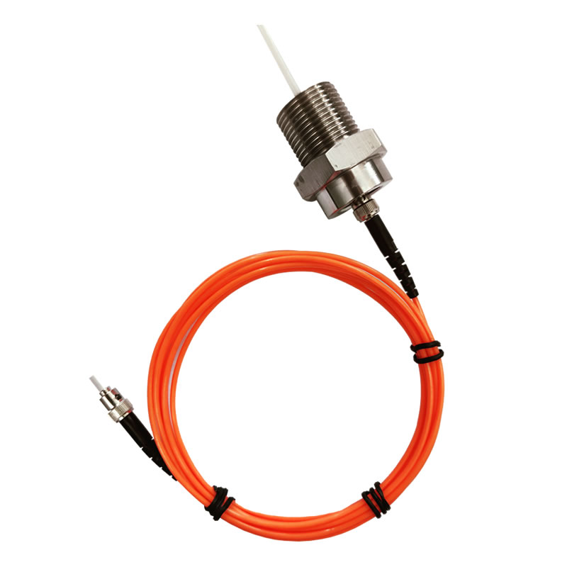
Armored Fiber Optic Temperature Sensor Probes for Transformer Windings
Le armored fiber optic temperature sensor probe is the core sensing element for oil-immersed transformer applications. These probes feature ruggedized protective sheaths — available in stainless steel, PTFE, ou des constructions de blindage composites - qui protègent la délicate fibre optique et la pointe de détection des contraintes mécaniques lors de l'enroulement de la bobine du transformateur, pressage, assemblée, remplissage d'huile sous vide, et des décennies de fonctionnement ultérieur immergé dans l'huile chaude du transformateur. Le blindage est spécialement conçu pour résister aux processus de fabrication propres à la production de transformateurs tout en conservant une compatibilité totale avec l'huile., inertie chimique, et conductivité thermique pour une mesure précise de la température. Sondes de température à fibre optique standards (non blindé) sont également disponibles pour les applications de transformateurs et de réacteurs de type sec où la protection contre l'immersion dans l'huile n'est pas requise. Les deux types de sondes présentent un diamètre compact de 2 à 3 mm et sont disponibles avec des longueurs de câble à fibre optique allant de 0 À 20 Mètres.
Contrôleurs de température à fibre optique pour transformateur de type sec
INNO dry-type transformer fiber optic temperature controllers are integrated devices combining fiber optic temperature sensing with automated transformer thermal management functions. Le BWDK-326 dry-type transformer temperature controller provides multi-channel fiber optic temperature input, LCD temperature display, programmable multi-stage temperature alarm outputs (pré-avertissement, alarme, voyage), automatic fan cooling group control, and RS485/Modbus RTU communication for remote monitoring integration. Le BWDK-S201 intelligent temperature controller offers enhanced features including expanded channel capacity and advanced alarm logic. These controllers serve as a direct, performance-superior replacement for traditional Pt100-based dry-type transformer temperature control systems, eliminating EMI-induced measurement errors and providing genuine fiber optic hot spot data for thermal protection decisions.
Multi-Channel Fiber Optic Temperature Demodulators for Transformer Monitoring
For multi-point surveillance de la température des enroulements de transformateur, INNO supplies démodulateurs de température à fibres optiques multicanaux in configurations from 6 À 64 Canaux. Each channel simultaneously and independently processes the fluorescence signal from one connected sonde de température à fibre optique, providing real-time temperature data for every monitored hot spot location. Le display-integrated fiber optic temperature demodulator combines signal processing with a local LCD display for direct reading at the transformer location. All demodulator models feature RS485/Modbus RTU communication output, configurable alarm relay contacts, and power supply options of AC 220V or DC 24V. For three-phase transformer applications, a 6-channel unit typically monitors 2 probes per phase; for larger transformers with additional monitoring requirements, 16-channel or 32-channel units provide the necessary capacity.
OEM Fiber Optic Temperature Sensing Module for Transformer Manufacturers
Le OEM single-channel fiber optic temperature sensing module est un compact, board-level component designed specifically for transformer manufacturers and control panel builders who need to embed fiber optic sensing capability directly into their own products. The module contains complete excitation, détection, and demodulation circuitry in a miniaturized form factor, with standard RS485/Modbus RTU output for direct connection to the host system’s controller or PLC. This enables transformer OEMs to offer surveillance des points chauds par fibre optique as an integrated feature of their transformers without developing proprietary optical sensing electronics.
Cloud Monitoring Software for Transformer Fiber Optic Systems
INNO propose customizable cloud platform monitoring software for centralized management of distributed transformer fiber optic monitoring installations. The platform supports remote real-time data acquisition from multiple transformer sites, multi-channel temperature visualization with graphical trending, configurable multi-level alarm management with notification dispatch (e-mail, SMS, push), historical data storage and trend analysis for insulation aging assessment, and integration interfaces for enterprise SCADA, DCS, SME, et systèmes de gestion d'actifs. The software is fully customizable to client-specific branding, dashboard layouts, user access structures, et exigences fonctionnelles.
9. Spécifications techniques du système de surveillance de la fibre optique du transformateur
![]()
The following table summarizes the standard technical specifications of INNO’s fiber optic transformer temperature monitoring system composants. All specifications are customizable to meet project-specific requirements.
| Paramètre | Spécification | Remarques |
|---|---|---|
| Précision des mesures | ±1°C | Across full operating range |
| Sensor Temperature Range | –40°C à +260°C | Gammes étendues disponibles sur demande |
| Longueur du câble à fibre optique | 0–20 mètres (standard) | Longueurs personnalisées disponibles |
| Temps de réponse | <1 deuxième | Suitable for dynamic thermal event tracking |
| Diamètre de la sonde | 2–3mm | Fits within winding slots and cooling ducts |
| Isolation électrique | Tenue en tension >100 kV | Isolation diélectrique complète |
| Canaux de surveillance | 1 / 6 / 16 / 32 / 64 Canaux | Selectable per application |
| Interface de communication | RS485 / Modbus RTU | Compatible with relay, SCADA, API, DCS |
| Sortie d'alarme | Contacts de relais configurables | Multi-stage: pré-alarme, alarme, voyage |
| Alimentation | AC 220 V ou DC 24 V | Sélectionnable à la commande |
| Demodulator Operating Environment | –20°C à +70°C, ≤95 % HR | Ambient conditions for demodulator host |
| Indice de protection de la sonde | IP65 | Etanche à la poussière, résistant aux jets d'eau |
| Compatibilité avec l'huile | Fully compatible with mineral and ester transformer oils | Armored probes designed for permanent immersion |
| Durée de vie | >25 années | Aucun recalibrage ou entretien requis |
| Certifications | CE, CEM, RoHS, OIN 9001/14001/27001/45001 | Global compliance |
Options de personnalisation
INNO supports full specification customization including extended temperature ranges, fiber cable lengths beyond 20 Mètres, specialized armored probe materials and geometries for specific transformer designs, protocoles de communication alternatifs, custom demodulator enclosure ratings, and tailored alarm logic configurations. Contact the INNO engineering team to discuss project-specific requirements.
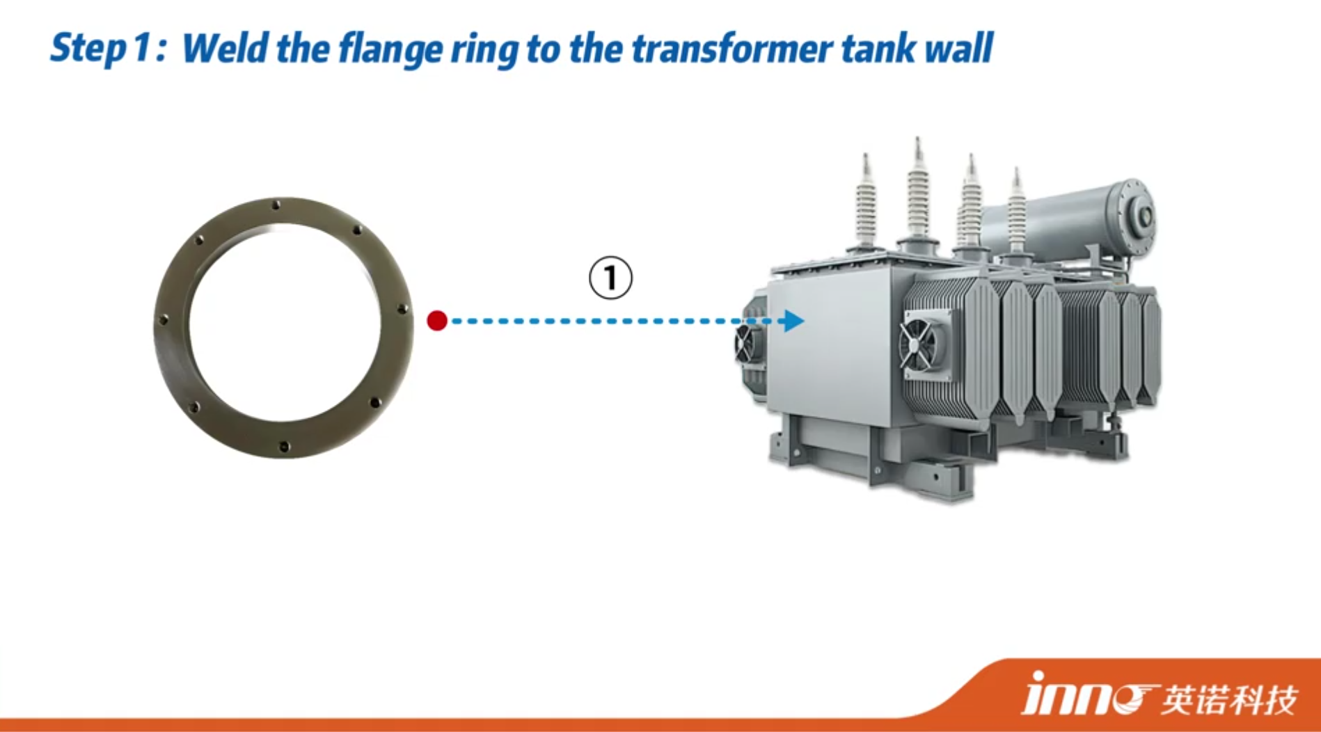
10. Installation du capteur à fibre optique du transformateur, Intégration & Guide de mise en service
Successful implementation of a fiber optic transformer monitoring system involves proper sensor installation, communication integration, and alarm configuration. The installation process is straightforward and can be accomplished by standard electrical and transformer technicians without specialized optical equipment or training.
Pre-Embedded Installation During Transformer Manufacturing
The most effective installation approach is to embed fiber optic temperature sensor probes within the transformer winding structure during the manufacturing process — before the windings are assembled onto the core and before the unit is filled with oil (for oil-immersed types) or encapsulated (for cast resin types). The transformer manufacturer installs the probes at the calculated hot spot locations — typically between conductor turns at the top of the inner or outer winding of the phase with the highest expected temperature. Le armored fiber optic probe is secured in position and the fiber cable is carefully routed along the winding, through the core-and-coil assembly, and out through a hermetic fiber optic feedthrough fitting installed in the transformer tank wall or enclosure panel. This pre-embedded approach provides the most accurate hot spot measurement, the most secure probe installation, and the most reliable long-term performance. INNO works directly with transformer manufacturers to specify probe placement, provide installation guidance, and ensure proper fiber routing and feedthrough sealing.
Retrofit Installation on Existing In-Service Transformers
Pour transformer retrofit fiber optic monitoring on existing operating units, probe installation is performed during a scheduled maintenance outage when the transformer is de-energized and (for oil-immersed units) the oil level is lowered or the unit is opened for inspection. Retrofit probes can be installed on accessible winding surfaces, at winding end blocks, or at other thermally representative locations reachable through inspection openings. While retrofit installation may not achieve the precise hot spot placement possible with pre-embedded installation, it still provides vastly more accurate and more valuable winding temperature data than external WTI or oil temperature measurement. The fiber feedthrough fitting is installed in an available tank penetration point, and the system is commissioned following the same procedures as a new installation.
System Communication & Intégration SCADA
Le démodulateur de température à fibre optique outputs real-time temperature data for all channels via RS485/Modbus RTU, which is the industry standard communication protocol supported by virtually all transformer protection relays, systèmes d'automatisation de sous-station, Plateformes SCADA, DCS controllers, and RTUs. Integration requires only standard RS485 wiring from the demodulator to the receiving device, and configuration of the Modbus register mapping in the host system. Temperature data from the fiber optic system can be used directly by transformer protection relays for thermal alarm and trip functions, displayed on local HMI panels for operator visibility, transmitted to central SCADA for fleet-wide thermal monitoring, and logged to historian databases for long-term insulation aging analysis. INNO provides complete Modbus register documentation and integration support for all mainstream relay and SCADA platforms.
Configuration du seuil d'alarme & Cooling System Linkage
The monitoring system supports configurable multi-stage temperature alarm logic. A typical transformer application uses three alarm levels: un pre-warning alarm (par ex., 110°C) that alerts operators and may initiate supplementary cooling, un high-temperature alarm (par ex., 120°C) that triggers enhanced cooling activation and load reduction consideration, et un trip alarm (par ex., 130°C or as defined by the transformer’s thermal design limits) that initiates automatic load shedding or transformer disconnection to prevent insulation damage. Pour transformateurs secs, le BWDK fiber optic temperature controller directly controls cooling fan groups based on measured winding temperatures, providing automatic thermal management without operator intervention. All alarm thresholds and control logic are fully programmable to match the specific thermal ratings and protection philosophy of each transformer.
11. Avantages opérationnels de la surveillance des transformateurs à fibre optique pour les services publics & Industrie
Exécution surveillance des transformateurs à fibre optique delivers tangible operational and financial value that extends far beyond simply knowing the winding temperature. The direct, précis, and continuous nature of fiber optic hot spot data enables a fundamentally more informed and optimized approach to transformer asset management.
Extend Transformer Insulation Life
By providing the actual winding hot spot temperature in real time, le système de surveillance à fibre optique enables operators to manage thermal loading precisely against the transformer’s true thermal limits rather than conservative estimated limits. Avoiding unnecessary thermal stress — even by a few degrees — can significantly extend cellulose insulation life according to the Arrhenius aging relationship. Inversement, early detection of unexpectedly high temperatures allows corrective action before cumulative thermal damage occurs. The net result is a measurably longer transformer service life and deferred capital replacement expenditure.
Enable Dynamic Overload Rating & Capacity Optimization
Traditional transformer loading practices are inherently conservative because the true hot spot temperature is unknown. Operators apply safety margins to compensate for WTI estimation uncertainties, effectively de-rating the transformer below its actual thermal capacity. Avec direct fiber optic hot spot measurement, operators can safely load the transformer closer to its true thermal limits — knowing in real time exactly how hot the winding actually is. Ce dynamic thermal rating capability can unlock 10–20% or more additional loading capacity from existing transformers, deferring or avoiding costly new transformer installations and network reinforcement investments.
Reduce Unplanned Outage Risk Through Predictive Thermal Monitoring
Abnormal temperature trends detected by continuous fiber optic monitoring — such as gradual increases in hot spot temperature at constant load, unexpected temperature asymmetry between phases, or abnormal thermal response during load changes — can indicate developing problems including blocked cooling ducts, deteriorating oil circulation, déformation de l'enroulement, ou dégradation de l'isolation. Early detection of these thermal anomalies enables condition-based maintenance interventions before they progress to outage-causing failures. Ce predictive maintenance capability directly reduces the frequency and cost of unplanned transformer outages.
Optimize Cooling System Energy Consumption
Systèmes de refroidissement des transformateurs (les fans, pompes, radiateurs) consume significant energy over the transformer’s operational life. When cooling activation is based on inaccurate WTI or top-oil temperature data, cooling systems may run when not needed or may not activate promptly enough when needed. Fiber optic hot spot data enables precise cooling control based on actual winding thermal conditions, reducing unnecessary cooling energy consumption while ensuring cooling is always adequate to protect the insulation. For dry-type transformers equipped with INNO fiber optic temperature controllers, fan group activation is directly controlled by real fiber optic winding temperatures — optimizing both energy efficiency and thermal protection.
Support Compliance with International Thermal Loading Standards
As IEC 60076-7 and IEEE C57.91 increasingly recognize and recommend direct fiber optic hot spot measurement as the reference method for transformer thermal assessment, implementing surveillance des transformateurs à fibre optique ensures compliance with current best practice and positions the asset owner for alignment with evolving regulatory and standards requirements.
Enable Digital Transformer Asset Management
The continuous, high-quality temperature data stream from Capteurs à fibre optique integrates directly into modern digital asset management platforms, enabling data-driven lifecycle management, fleet-wide thermal performance benchmarking, and evidence-based capital planning. Combined with INNO’s cloud monitoring software platform, fiber optic thermal data becomes a foundation for comprehensive surveillance de l'état des transformateurs and enterprise asset intelligence.
12. Références mondiales de projets & Base installée
INNO surveillance des transformateurs à fibre optique technology is validated through extensive real-world deployment across diverse transformer types, niveaux de tension, climatic conditions, et environnements d'application. Avec plus 3000 installed monitoring systems operating worldwide and exports to more than 15 countries across Asia, Europe, les Amériques, le Moyen-Orient, Océanie, et l'Afrique, the company has built a substantial body of field-proven reference projects.
Representative Project Categories
Utility substation transformer monitoring projects represent the largest deployment category, avec capteurs de température d'enroulement de fibre optique installed on transmission and distribution transformers ranging from 10 kV à 500 classe kV, providing real-time hot spot data to substation automation and SCADA systems. Dry-type transformer fiber optic temperature controller batch supply projects encompass large-scale deployments for commercial and industrial dry-type transformer fleets, replacing legacy Pt100 temperature control systems with superior fiber optic sensing. Generator stator winding fiber optic temperature monitoring projects involve embedding fluorescent probes directly in generator stator slots for continuous winding thermal management. Industriel rectifier transformer and furnace transformer monitoring projects address the demanding thermal conditions of high-current industrial loads. International export projects span multiple regions including Southeast Asia (Philippines, Malaisie, Thaïlande, Singapour, Indonésie, Viêt Nam), Asie de l'Est (Corée du Sud, Japon), le Moyen-Orient (Émirats arabes unis), Afrique (Afrique du Sud), Océanie (Australie), Amérique du Sud (Brésil), et Amérique du Nord (Canada, États-Unis, Mexique), as well as European markets (Allemagne, France, Pays-Bas, Italie, Royaume-Uni).
Installed Base Confidence
The breadth and scale of INNO’s installed base — 3000+ systèmes à travers 15+ countries operating in conditions ranging from tropical equatorial climates to cold northern regions, from coastal marine environments to high-altitude installations — provides strong empirical validation of the system’s long-term reliability, Précision de mesure, and environmental durability. Prospective customers are welcome to request detailed project references and case studies relevant to their specific transformer type and application.
13. Marque privée OEM & Développement personnalisé ODM pour les fabricants de transformateurs

INNO has established deep partnerships with transformer manufacturers, intégrateurs de systèmes, and distributors worldwide through flexible OEM and ODM cooperation models tailored to the specific commercial and technical needs of each partner.
OEM Private-Label Supply for Transformer OEMs
En tant que dévoué OEM fiber optic transformer monitoring system manufacturer, INNO delivers complete private-label supply services to transformer producers who want to offer fiber optic hot spot monitoring as a standard or optional feature of their transformers. OEM partners specify their own branding, product labeling, documentation format, and packaging requirements, tandis qu'INNO gère toute la fabrication, assurance qualité, étalonnage, et processus de certification. Available OEM products include sondes de température blindées à fibre optique with custom cable lengths and connector types, démodulateurs multicanaux with custom enclosures and labeling, régulateurs de température pour transformateurs de type sec, et modules de détection OEM monocanal for embedded integration into transformer control panels.
ODM Custom Development
For transformer manufacturers and system integrators requiring solutions beyond standard product configurations, INNO’s R&D team collaborates on Développement personnalisé ODM projets. Customization capabilities include specially designed probe packaging for unique winding geometries, custom armoring materials and fiber routing solutions for specific transformer manufacturing processes, sur mesure demodulator hardware and firmware configurations, modified communication protocols and register mappings, custom alarm logic for specific transformer protection schemes, et branded monitoring software platforms with partner-specific interfaces and functionality.
Distributeur & System Integrator Partnerships
INNO supports global market development through distributor and agent partnerships in key markets. Partners benefit from competitive pricing structures, comprehensive product training, matériel de support marketing, joint project engineering support, et gestion de compte dédiée. System integrators receive full technical documentation, integration engineering assistance, and flexible product configurations to incorporate fiber optic transformer thermal monitoring into their broader transformer protection and condition monitoring solution offerings. The INNO commercial team provides responsive one-on-one support with rapid quotation turnaround for all partnership inquiries.
14. Pourquoi choisir INNO comme fournisseur de surveillance de transformateur à fibre optique

Selecting a supplier for surveillance des transformateurs à fibre optique is a long-term commitment that directly impacts transformer asset safety, monitoring reliability, et coût total de possession. INNO has earned the trust of transformer manufacturers, utilitaires, and industrial operators worldwide through consistent product quality, deep application expertise, and dependable long-term partnership support.
20+ Years of Specialized Fiber Optic Temperature Sensing Expertise
INNO’s entire business is built around one core competency: fiber optic temperature sensing for high-voltage and harsh-environment applications. This two-decade singular focus has produced deep domain knowledge, procédés de fabrication raffinés, and a product portfolio tested through thousands of real-world transformer installations — a level of specialization that generalist sensor companies or diversified technology conglomerates cannot replicate.
Full Value Chain Under One Roof
From fluorescent phosphor material formulation and fabrication de sondes de capteur, through optical system design and demodulator electronics production, to firmware development, system assembly, et cloud software platform engineering — INNO controls every element of the product value chain in-house. This vertical integration ensures consistent quality, enables rapid customization, and provides single-source technical accountability.
Complete Transformer Monitoring Product Line — One-Stop Supply
With a product range covering armored transformer probes, régulateurs de température pour transformateurs de type sec, démodulateurs multicanaux, Modules de détection OEM, et cloud monitoring software, INNO provides everything needed for a complete transformer fiber optic monitoring system from a single supplier. This eliminates multi-vendor coordination, ensures full system compatibility, and simplifies procurement and support.
3000+ Proven Installations Across 15+ Pays
Real-world performance is the ultimate validation. INNO’s installed base of 3000+ operating systems across 15+ countries — spanning diverse transformer types, classes de tension, climatic zones, and industry sectors — provides conclusive evidence of long-term product reliability and global application versatility.
Full International Certifications
All INNO products carry CE, CEM, RoHS, et ISO 9001/14001/27001/45001 attestations, ensuring compliance with international quality, sécurité, environnemental, and electromagnetic compatibility standards required for global transformer supply chains.
Responsive Customization & Assistance dédiée
Si l'exigence est un produit de catalogue standard, a custom OEM-branded sensor, a tailored demodulator configuration, or a complete ODM system development, Les équipes techniques et commerciales d’INNO offrent des solutions réactives, technically informed support with competitive lead times and dedicated one-on-one project management.
Contacter INNO
Pour discuter de votre surveillance des transformateurs à fibre optique Exigences, request a technical proposal, or obtain a customized quotation, contactez directement l'équipe INNO:
Messagerie électronique: web@fjinno.net
WhatsApp (en anglais) / WeChat (en anglais seulement): +8613599070393
Téléphone: +8613599070393
Téléphone de l'entreprise: +8659183846499
Adresse: Non. 12 Route de l’ouest de Xingye, Ville de Fuzhou, Fujian, Chine
Site web: www.fjinno.net
15. Questions fréquemment posées sur la surveillance des transformateurs à fibre optique
T1: What is fiber optic transformer monitoring and how does it differ from a traditional winding temperature indicator (WTI)?
Surveillance des transformateurs à fibre optique uses fluorescent fiber optic sensor probes installed directly at the winding hot spot location inside the transformer to measure the actual temperature in real time. A traditional WTI, par contre, does not directly measure winding temperature — it estimates the hot spot temperature by measuring top-oil temperature and adding a simulated thermal increment derived from load current via a heater coil. This indirect estimation introduces errors of 10–15°C or more. Fiber optic sensing eliminates this estimation error entirely, fournir directement, sans dérive, ±1°C accuracy measurement of the true winding hot spot temperature.
T2: Can fiber optic sensor probes survive long-term immersion in transformer insulating oil?
Oui. INNO sondes blindées de capteur de température à fibre optique are specifically engineered for permanent immersion in transformer oil over the full 25+ année de vie de l'équipement. The armored construction uses oil-resistant materials — stainless steel, PTFE, and specialty polymers — that maintain chemical inertness, intégrité mécanique, and optical performance in hot mineral oil and synthetic ester insulating fluids. The fiber optic sensor tip is hermetically sealed against oil ingress, and the probe has been validated through accelerated aging testing and confirmed by thousands of installed field units operating in oil-immersed transformers worldwide.
T3: How many temperature monitoring points does a typical transformer require?
The number of monitoring points depends on the transformer size, classe de tension, et configuration d'enroulement. A typical three-phase transformer installation uses 2 À 6 fiber optic sensor probes — commonly 1 À 2 probes per phase, placed at the calculated hot spot location in each winding. Plus grand, higher-voltage transformers or units with multiple winding sections may require additional monitoring points. Single-phase transformers (such as large generator step-up transformers) nécessitent généralement 2 À 4 sondes. INNO multi-channel fiber optic demodulators sont disponibles dans 6, 16, 32, et 64 channel configurations to accommodate any monitoring density requirement.
T4: Can fiber optic temperature sensors be retrofitted to existing transformers already in service?
Oui. While the most precise hot spot probe placement is achieved through pre-embedded installation during transformer manufacturing, retrofit fiber optic monitoring is feasible and widely practiced on existing in-service transformers. Retrofit installation is performed during a scheduled maintenance outage, with probes installed at accessible winding surfaces or thermally representative locations. A hermetic fiber optic feedthrough is installed in an available tank wall penetration point. Although retrofit probe placement may not precisely coincide with the absolute winding hot spot, the direct temperature data obtained is still significantly more accurate and valuable than WTI or top-oil temperature measurement.
Q5: What is the measurement accuracy and response time of the fiber optic transformer monitoring system?
INNO fiber optic transformer monitoring system achieves measurement accuracy of ±1°C across the full operating range of –40°C to +260°C, with a thermal response time of less than 1 deuxième. This combination of high accuracy and fast response enables both precise steady-state thermal assessment and real-time tracking of dynamic thermal events such as overload transients, load step changes, and post-fault temperature recovery.
Q6: Does the fiber optic transformer monitoring system require periodic calibration or maintenance?
Non. The fluorescence lifetime measurement principle is inherently drift-free — the measured parameter (temps de décroissance) depends only on the sensing material temperature and is independent of optical signal amplitude, pertes de fibres, or component aging. The inorganic phosphor sensing material does not degrade in transformer oil or under thermal cycling. Par conséquent, the system maintains its factory calibration accuracy throughout its entire 25+ year operational life with zero maintenance, zero recalibration, and zero component replacement. This is a significant operational and cost advantage over WTIs, Pt100 sensors, et thermocouples, all of which require periodic recalibration or replacement.
Q7: How does the fiber optic monitoring data integrate with transformer protection relays and SCADA systems?
Le démodulateur de température à fibre optique produit des données de température en temps réel pour tous les canaux via RS485 avec le protocole Modbus RTU — la norme universelle pour la communication industrielle. Il s'interface directement avec les relais de protection des transformateurs (pour les fonctions d'alarme thermique et de déclenchement), systèmes d'automatisation de sous-station, écrans IHM locaux, Postes maîtres SCADA, DCS controllers, et plateformes d'historien de données. L'intégration nécessite uniquement un câblage RS485 standard et une configuration de registre Modbus dans l'appareil de réception. INNO fournit une documentation complète de mappage de registre et un support d'intégration pour toutes les plates-formes de relais et SCADA grand public.. Des protocoles de communication personnalisés peuvent également être développés pour des exigences d'intégration spécifiques.
Q8: Les mêmes sondes à fibre optique sont-elles utilisées pour les transformateurs immergés dans l'huile et de type sec ??
La technologie de détection fluorescente de base est la même, but the probe packaging differs to suit each application environment. Oil-immersed transformer applications utiliser sondes de température blindées à fibre optique with oil-resistant protective sheaths designed for permanent immersion. Dry-type transformer applications typically use standard fiber optic temperature probes or surface-mount configurations that do not require oil-immersion armor. Pour transformateurs secs, INNO also offers integrated fiber optic temperature controllers (BWDK series) that combine sensing with automated fan control and thermal protection functions. INNO’s engineering team advises the appropriate probe type for each specific transformer application.
Q9: What international standards support direct fiber optic hot spot temperature measurement in transformers?
Both IEC 60076-7 (Power transformers — Loading guide for mineral-oil-immersed power transformers) et IEEE C57.91 (Guide for Loading Mineral-Oil-Immersed Transformers and Step-Voltage Regulators) explicitly address direct winding hot spot temperature measurement using fiber optic sensors. Both standards recognize fiber optic sensing as the reference method for determining actual hot spot temperatures and use fiber optic measurement data as the basis for validating thermal models. CEI 60076-2 (Temperature rise for liquid-immersed transformers) also references fiber optic sensors for temperature rise test measurements. Specifying surveillance des transformateurs à fibre optique aligns with current international best practice and evolving industry standards.
Q10: How can I get a quotation or technical proposal for my transformer fiber optic monitoring project?
Contactez INNO directement par email à web@fjinno.net, WhatsApp ou WeChat sur +8613599070393, ou téléphone de l'entreprise au +8659183846499. You can also submit a project inquiry through the company website at www.fjinno.net/contact. Pour recevoir un précis, project-specific proposal, provide details including: type de transformateur (oil-immersed or dry-type), voltage class and MVA rating, number of transformers to be monitored, desired number of monitoring points per transformer, new installation or retrofit, exigences en matière d'interface de communication, and any special environmental or customization needs. The INNO engineering and sales team provides responsive one-on-one support with rapid quotation turnaround.

Capteur de température à fibre optique, Système de surveillance intelligent, Fabricant de fibre optique distribuée en Chine
 |
 |
 |