 INNO faseroptische Temperatursensoren ,Temperaturüberwachungssysteme.
- Dual Technology Solutions: Fluorescent fiber optic and distributed fiber optic temperature sensing systems meet diverse industrial equipment monitoring needs
- Überlegene Leistung: Fluorescent systems offer <1 zweite Reaktionszeit, ±1°C Genauigkeit, -40°C bis 260 °C Bereich; distributed systems provide 1-second response
- Global Applications: Thousands of systems successfully deployed across Europe, Nordamerika, and Asia-Pacific in power, Petrochemie, and metallurgical industries
- Proven Advantages: Im Vergleich zu Thermoelementen, RTDs, and infrared thermometry, Glasfasertechnologie offers intrinsic safety and electromagnetic immunity
- Customization Available: Sondendurchmesser, Faserlänge, Temperaturbereich, and other parameters customizable to specific operational requirements
1. What is an Industrial Machine Monitoring System?

Ein industrial machine monitoring system is an intelligent platform integrating sensing, Datenerfassung, Analyse, and warning capabilities designed to track equipment operational status in real-time. These systems deploy various sensors to continuously collect critical parameters including temperature, Vibration, Druck, und aktuell, enabling enterprises to achieve vorausschauende Wartung and optimize production management.
Temperaturüberwachung represents one of the most fundamental yet critical functions in industrial machine monitoring. Abnormal equipment temperatures often signal early-stage failures, and timely detection can prevent major accidents and economic losses.
Unser faseroptische Temperaturerfassungssysteme specialize in providing highly reliable temperature monitoring solutions for industrial equipment, supporting two core technologies:
Kerntechnologien
- Fluoreszierende faseroptische Temperaturmessung: Ideal for precise point measurements at critical locations
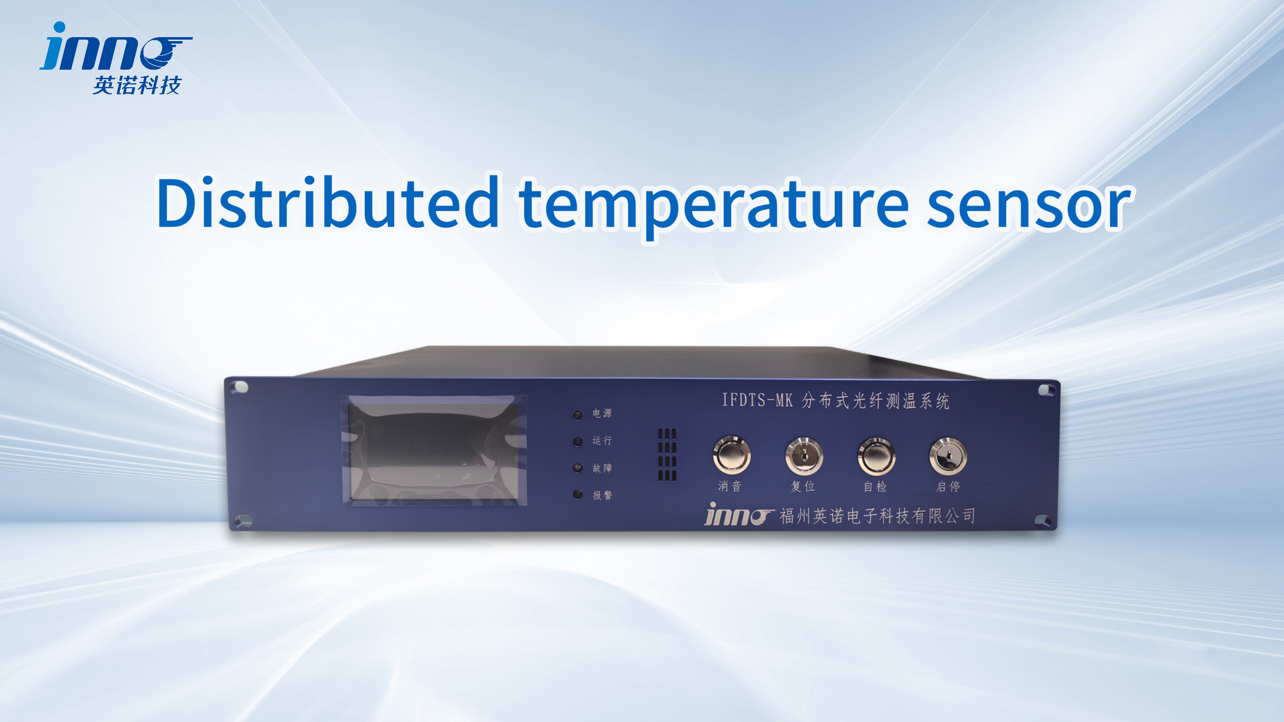
- Verteilte Glasfaser-Temperaturüberwachung (DTS): Suitable for long-distance continuous monitoring
The system architecture comprises fiber optic sensing probes, signal demodulation equipment, industrial communication modules, and monitoring software platforms, seamlessly integrating with existing industrial automation systems.
2. Why is Temperature Monitoring Critical for Industrial Equipment?
Verhinderung katastrophaler Ausfälle
Equipment overheating ranks among the leading causes of industrial accidents. Electrical equipment contact failure, excessive mechanical friction, and uncontrolled chemical reactions all manifest as abnormal temperature increases. Temperaturüberwachung in Echtzeit provides early warnings during the incubation stage, Brände verhindern, Explosionen, and other severe consequences.
Extending Equipment Service Life
Prolonged operation in high-temperature environments accelerates equipment aging. By mastering equipment thermal states through Temperaturüberwachungssysteme and optimizing operational parameters, companies can significantly extend equipment lifespan and reduce capital expenditures.
Enhancing Production Efficiency
Many industrial production processes require strict temperature control. Präzise Temperaturüberwachungsdaten supports process optimization, improves product quality and production efficiency, and reduces scrap rates.
Meeting Regulatory Compliance
Safety regulatory authorities worldwide mandate temperature monitoring for critical equipment in high-risk industries. Umfassend equipment monitoring systems help enterprises pass safety audits and obtain production licenses.
Supporting Intelligent Decision-Making
Accumulated temperature data provides the foundation for equipment health management, Wartungsplanung, and energy management optimization—essential components of industrial digital transformation.
3. What is Fiber Optic Temperature Sensing Technology?

Faseroptische Temperaturerfassung is a technology that utilizes the physical properties of optical fibers for temperature measurement. Im Gegensatz zu herkömmlichen elektrischen Sensoren, faseroptische Sensoren use optical signals as information carriers, offering unique advantages including intrinsic safety, elektromagnetische Störfestigkeit, and long-distance transmission capabilities.
Technology Development Background
Fiber optic sensing technology originated in the 1970s from optical fiber communication research. Scientists discovered that light propagating through optical fibers produces various scattering and fluorescence phenomena correlated with environmental temperature, Stress, and other physical quantities. Nach jahrzehntelanger Entwicklung, faseroptische Sensorik has become a mature technology in industrial monitoring applications.
Kernvorteile
Eigensicherheit
Faseroptische Sensoren contain no electrical components, require no on-site power supply, and produce no electrical sparks, enabling safe use in flammable and explosive environments. This represents the fundamental reason why high-risk industries like chemical and coal mining prefer fiber optic technology.
Immunität gegen elektromagnetische Störungen
In strong electric and magnetic field environments, traditional electrical sensors easily suffer interference causing measurement inaccuracies. Optical signals remain completely unaffected by electromagnetic fields, ensuring data accuracy and reliability.
Corrosion and High-Temperature Resistance
Optical fiber material consists of quartz glass with stable chemical properties. Combined with special protective sheaths, fibers can operate long-term in acidic, alkaline, and high-temperature harsh environments.
Long-Distance Lossless Transmission
Optical signals maintain signal quality across kilometers of fiber transmission without requiring repeater amplification, simplifying system design.
4. How Does Fiber Optic Temperature Measurement Compare to Traditional Methods?
Industrial Temperature Measurement Technology Comparison
| Vergleichsartikel | Fluoreszierende Glasfaser | Verteilte Glasfaser | Thermoelement | FTE | Infrarot-Thermometrie |
|---|---|---|---|---|---|
| Messgenauigkeit | ±1°C | ±1-2°C | ±1-2°C | ±0,1–0,5 °C | ±2-5°C |
| Ansprechzeit | <1 zweite | 1 zweite | 1-10 Sekunden | 5-30 Sekunden | <1 zweite |
| Temperaturbereich | -40 bis 260°C (anpassbar) | -40 to 600°C | -200 to 1800°C | -200 bis 850°C | -50 to 3000°C |
| EMI-Immunität | Vollständige Immunität | Vollständige Immunität | Anfällig | Anfällig | N / A |
| Eigensicherheit | Ja | Ja | NEIN | NEIN | Ja |
| Messentfernung | Einziger Punkt (0-80m fiber) | Continuous 5-30km | Limited by cable length | Limited by cable length | Sichtlinie |
| Langzeitstabilität | Exzellent (kein Drift) | Exzellent | Prone to drift | Gut | Environment dependent |
| Wartungskosten | Sehr niedrig | Niedrig | Medium (requires calibration) | Medium | Medium |
| Mehrpunktüberwachung | 1-64 Punkte pro Kanal | Thousands of points per fiber | Individual wiring per point | Individual wiring per point | Point-by-point scanning |
| Lebensdauer | 20+ Jahre | 20+ Jahre | 3-5 Jahre | 5-10 Jahre | 5-10 Jahre |
Significant Advantages of Fiber Optic Technology
Harsh Industrial Environment Adaptability
In Umspannwerken, Schaltanlage, and other strong electromagnetic field environments, thermocouple and RTD measurement data frequently fluctuate and produce errors, Dies führt zu Fehlalarmen oder verpassten Erkennungen. Faseroptische Sensoren remain completely unaffected by electromagnetic interference and can operate stably in 1000kV ultra-high voltage environments.
A provincial grid company conducted comparative testing by installing both thermocouples and fluoreszierende faseroptische Sensoren on the same batch of switchgear. After six months of operation, thermocouples showed a 23% Fehlalarmrate, while the fiber optic system achieved zero false alarms and zero missed detections.
Hazardous Area Application Advantages
Temperature monitoring in petrochemical facilities has always been challenging. Traditional electrical sensors require complex explosion-proof designs with high installation and maintenance costs, yet still pose safety risks. Faseroptische Sensoren are intrinsically safe, require no explosion-proof certification, and can be directly applied in explosive gas environments.
5. What’s the Difference Between Fluorescent and Distributed Fiber Optic Sensing?
Technical Principle Comparison
Fluoreszierende faseroptische Temperaturmessung
Der fluoreszierende faseroptische Sensorik probe tip contains rare-earth fluorescent material. When excitation light illuminates the fluorescent material, it becomes excited and emits fluorescence signals. The fluorescence decay time constant exhibits a definite functional relationship with temperature, allowing precise temperature calculation through accurate decay time measurement.
This measurement method’s key advantage lies in its dependence solely on time parameters, independent of light intensity, Faserbiegeverlust, connector loss, und andere Faktoren, ensuring excellent long-term stability without zero-point or gain drift.
Verteilte Temperaturerfassung (DTS)
Verteilte Systeme operate on the Raman scattering effect. Laser pulses traveling through optical fiber produce backscattered light, with anti-Stokes light intensity being temperature-sensitive. By analyzing scattered light signals returning at different times using Optical Time Domain Reflectometry (OTDR), the system simultaneously obtains temperature and spatial location information.
This effectively transforms a single fiber into a continuous temperature sensor, with measurement points every 0.5-2 Meter, enabling a single fiber to cover several kilometers.
Application Scenario Selection
| Application Need | Empfohlene Technologie | Begründung |
|---|---|---|
| High-voltage switchgear contact monitoring | Fluoreszierende Glasfaser | Precise specific point monitoring, schnelle Reaktion, compact probe |
| Temperatur der Transformatorwicklung | Fluoreszierende Glasfaser | Distributed multi-point placement, hohe Genauigkeitsanforderungen |
| Stromkabeltunnel | Verteilte Glasfaser | Long-distance continuous monitoring, precise hotspot localization |
| Oil pipeline leak detection | Verteilte Glasfaser | Multi-kilometer range monitoring, rapid anomaly localization |
| Storage tank temperature distribution | Verteilte Glasfaser | Vertical temperature profile monitoring |
| Rotating machinery bearings | Fluoreszierende Glasfaser | Schnelle Reaktion, customizable small-diameter probes |
Fluorescent Fiber Optic System Technical Specifications
- Ansprechzeit: <1 zweite
- Messgenauigkeit: ±1°C
- Temperaturbereich: -40 bis 260°C (higher temperatures customizable)
- Faserlänge: 0-80 Meter (per probe)
- Sondendurchmesser: Standard 3mm, 2mm; smaller diameters customizable
- Points per Channel: 1-64 Punkte
- Schutzklasse: IP67 (Standard), IP68 (optional)
- Ausgabeschnittstelle: RS485, Modbus RTU/TCP, 4-20mA
All technical parameters are customizable based on specific application requirements, including special temperature ranges, ultra-compact probes, and specialized sheath materials.
Distributed Fiber Optic System Technical Specifications
- Ansprechzeit: 1 zweite
- Messgenauigkeit: ±1-2°C
- Temperaturbereich: -40 to 600°C (Standard)
- Überwachungsentfernung: 5-30 Kilometer (single fiber)
- Räumliche Auflösung: 0.5M, 1M, 2m options
- Abtastintervall: 0.5-2 Meter
- Ausgabeschnittstelle: Ethernet, OPC, Modbus TCP
6. How Do Industrial Temperature Monitoring Systems Operate?
Fluorescent Fiber Optic Monitoring System Workflow
Schritt 1: Temperature Signal Capture
Fluoreszierende faseroptische Sonden are installed at critical locations on monitored equipment. The demodulator sends excitation light pulses to probes at a fixed frequency (typically 100-1000Hz). Excitation light transmits through the fiber to the probe tip’s fluorescent material, causing fluorescence emission.
Schritt 2: Fluorescence Signal Analysis
Nach Aufregung, the fluorescent material emits fluorescence in exponential decay fashion. The demodulator precisely measures the fluorescence decay time constant, which maintains a definite mathematical relationship with temperature at the probe location.
Schritt 3: Temperaturberechnung
Built-in processing algorithms in the demodulator calculate actual temperature values from fluorescence decay time. Since measurement is time-based rather than intensity-based, Faserbiegen, connector attenuation, and other factors don’t affect results, ensuring long-term stability.
Schritt 4: Data Transmission and Processing
Calculated temperature data transmits through industrial communication interfaces (RS485, Modbus, usw.) to monitoring software or host systems. Software platforms display real-time temperature curves, record historical data, and execute alarm logic.
The entire process from temperature change to system alarm display takes less than 1 zweite, meeting fast response requirements.
Distributed Fiber Optic Monitoring System Workflow
Schritt 1: Optical Pulse Emission
Der DTS host unit launches high-energy laser pulses into the fiber. Pulses propagate forward through the fiber at the speed of light (etwa 200,000 km/s).
Schritt 2: Scattered Light Collection
As optical pulses propagate through fiber, each location produces Rayleigh scattering, Raman-Streuung, und Brillouin-Streuung. Anti-Stokes light from Raman scattering is temperature-sensitive, intensifying with temperature increases.
Schritt 3: Temperature Inversion Calculation
By analyzing the intensity ratio of anti-Stokes to Stokes light combined with OTDR technology, the system calculates temperature values at each spatial location. Typical systems simultaneously obtain temperature data from thousands of measurement points.
Schritt 4: Temperature Field Reconstruction
Software reconstructs discrete temperature measurement point data into continuous temperature distribution curves, displaying the temperature field along the entire fiber in real-time. Any location experiencing temperature anomalies triggers immediate system identification and alarming, providing precise anomaly location coordinates.
Distributed system scan cycles typically run at 1 zweite, updating full-length temperature distribution data every second.
7. What are the Technical Specifications of Fiber Optic Sensors?
Core Performance Indicators
Messgenauigkeit
Measurement accuracy refers to the deviation between system measurements and true values. Unser fluoreszierende Glasfasersysteme achieve standard accuracy of ±1°C, reaching ±0.5°C in the commonly used 20-100°C temperature range. Verteilte Systeme maintain standard accuracy of ±1-2°C.
Ansprechzeit
Response time defines the duration from temperature step change to the system displaying 90% of the change. Fluoreszierende Glasfasersysteme respond in <1 zweite, while distributed systems achieve 1-second response. Rapid response proves critical for applications requiring timely warnings.
Customizable Parameters
We understand every industrial application has unique requirements. The following parameters support customization:
- Extended temperature ranges (z.B., -200 to 400°C)
- Ultra-compact probe diameters (minimum 1mm)
- Special fiber lengths (übersteigend 80 Meter)
- Special mechanical structures (z.B., 90-degree bend probes)
- Specialized sheath materials (z.B., titanium alloy sheaths)
- Custom communication protocols
8. Which Industrial Machines Require Real-Time Temperature Monitoring?
Power Generation Equipment
Überwachung von Schaltanlagen
In Hochspannungsschaltanlagen, Trennschalter, Kontakte des Leistungsschalters, and busbar connections represent key temperature monitoring points. Increased contact resistance causes localized overheating, with temperatures rising from normal values to 150°C+ within minutes, potentially causing equipment burnout or fires.
Leistungstransformatoren
Groß Leistungstransformator winding temperatures directly affect equipment lifespan and operational safety. Traditional top-oil temperature measurement cannot reflect winding hot-spot temperatures. Faseroptische Sonden can be installed directly inside windings, monitoring hot-spot temperatures in real-time.
Cable Systems
Stromkabel in tunnels, Gräben, or direct burial experience localized overheating from overloading, joint failures, or external damage. Distributed fiber optic deployed parallel to cables monitors full-length temperature, rapidly localizing fault points.
Petrochemical Equipment
Lagertanks
Large crude oil and refined product storage tanks require liquid level and temperature distribution monitoring. Verteilte Glasfaser arranged vertically from tank top to bottom provides real-time temperature profiles at different heights, preventing fire risks.
Pipelines
Long-distance pipeline temperature monitoring enables leak detection and flow monitoring. Pipeline leaks produce temperature anomalies near leak points. Distributed fiber optic deployed along pipelines rapidly localizes leaks across tens of kilometers.
Reactors and Towers
Chemical reactor temperature control directly impacts product quality and safety. Multi-point fiber optic temperature systems monitor temperature distribution at different reactor locations, optimizing reaction conditions.
Metallurgical Equipment
Blast Furnaces
Iron-making blast furnace body temperature monitoring evaluates refractory lining condition. Verteilte Glasfaser arranged on the furnace shell monitors the furnace body temperature field, detecting lining burnthrough hazards promptly.
Heating Furnaces
Steel rolling heating furnaces require precise temperature control. Multi-point fiber optic temperature systems monitor temperatures in different furnace zones, supporting automatic control system optimization of heating curves.
Mining Equipment
Erdkabel
Coal mine underground cables represent major fire hazards. Distributed fiber optic temperature systems deployed along cables monitor full-length temperatures in real-time, immediately alarming and localizing temperature anomalies.
Belt Conveyors
Belt conveyor roller bearing failures and belt misalignment friction cause overheating. Distributed fiber optic arranged along belts continuously monitors temperature, Brände verhindern.
9. How Do Power Equipment Monitoring Systems Prevent Failures?
Early Identification of Switchgear Temperature Anomalies
High-voltage switchgear failures often exhibit clear temperature signatures. Contact deterioration increases contact resistance, generating additional Joule heating. During early fault development stages, temperature increases may only be 5-10°C—difficult to detect through manual inspection—but Glasfaser-Temperatursysteme precisely capture these changes.
Prädiktive Wartungsstrategien
Temperature Threshold Management
Based on equipment types and operational experience, scientific temperature thresholds are established:
- Normal operating temperature: Typically below ambient temperature +30°C
- Warning temperature: Exceeds normal by 10-15°C
- Alarmtemperatur: Exceeds normal by 20-30°C
- Emergency temperature: Exceeds 80-100°C
Temperature Trend Monitoring
Single temperature increases may result from normal factors like load increases. Systems analyze temperature change trends to identify abnormal patterns:
- Continuous slow rise: May indicate contact deterioration
- Periodic fluctuation: May reflect load variations (normal phenomenon)
- Sudden jump: May indicate severe fault requiring immediate action
10. What are the Special Requirements for Petrochemical Industry Machine Monitoring?
Explosion-Proof Safety is Paramount
Petroleum and chemical facilities contain numerous flammable and explosive gases and liquids, with equipment areas typically classified as explosion hazard zones (Zone 0, Zone 1, Zone 2). Traditional electrical temperature measurement equipment requires strict explosion-proof certification, with complex explosion-proof structures, high costs, and difficult maintenance.
Faseroptische Sensoren are intrinsically safe, producing no electrical sparks, and can be used in any hazardous area without explosion-proof certification. This represents the fundamental reason for large-scale adoption of fiber optic temperature technology in the petrochemical industry.
Long-Distance Distributed Monitoring Needs
Petrochemical facility pipelines and cables often extend for kilometers. Traditional temperature measurement methods require individual wiring for each measurement point, creating enormous installation workloads. Distributed fiber optic temperature systems cover kilometers with a single fiber, dramatically simplifying installation.
11. What Challenges Exist in Metallurgical Equipment Temperature Monitoring?
Extreme High-Temperature Environments
Many metallurgical industry equipment operates at extremely high temperatures. Steel-making converter internal temperatures reach 1600°C, heating furnace chamber temperatures 1200-1300°C, and continuous casting slab discharge temperatures exceed 1000°C. Unser distributed fiber optic temperature systems with standard -40 to 600°C ranges meet most high-temperature monitoring needs for furnace shells and water cooling systems.
Severe Mechanical Vibration
Rolling mills, crushers, and similar equipment generate intense vibration during operation. Traditional sensor electrical connections easily loosen or damage from vibration. Faseroptische Sensoren have no electrical connections, and fiber material flexibility provides strong vibration resistance.
Severe Electromagnetic Interference
Metallurgical facilities use high-power electrical equipment with complex electromagnetic environments. Induction furnaces and electric arc furnaces generate strong electromagnetic fields that severely interfere with traditional electrical sensors. Faseroptische Sensoren remain completely immune to electromagnetic interference, making them ideal for strong electromagnetic environments.
12. What Value Does Industrial Equipment Condition Monitoring Deliver?
Direct Economic Benefits
Reduced Equipment Failure Rates
Through continuous temperature monitoring and early warning, intervention occurs before faults develop to severe stages. Data shows that implementing faseroptische Temperaturüberwachung reduces equipment failure rates by an average of 50-70%.
Decreased Unplanned Downtime Losses
For continuous production enterprises, unplanned equipment downtime causes enormous economic losses. For refining units, Zum Beispiel, a million-ton catalytic cracking unit shutdown for one day results in losses reaching several million dollars.
Extended Equipment Service Life
Equipment overheating operation accelerates insulation aging, material fatigue, und Schmierstoffverschlechterung. Durch Temperaturüberwachung, ensuring equipment operates within reasonable temperature ranges significantly extends service life.
Indirect Economic Benefits
Verbesserungen der Energieeffizienz
Precise temperature data supports production process optimization, improving energy utilization efficiency. One cement enterprise utilized rotary kiln distributed fiber optic temperature data to optimize combustion control strategy, improving thermal efficiency by 5% and saving over $1.2 million in fuel costs annually.
Product Quality Enhancement
Many product qualities directly correlate with production process temperatures. Precise temperature control improves product consistency and qualification rates.
13. How are Global Enterprises Using Fiber Optic Monitoring Systems?
European Applications
German Automotive Manufacturing Paint Line Monitoring
A renowned German automaker deployed faseroptische Temperaturüberwachungssysteme on its paint production lines. Paint process drying ovens require precise temperature curve control, with temperature deviations affecting coating quality. The company installed distributed fiber optic temperature systems in drying ovens across six paint lines. After implementation, coating quality stability significantly improved, with defect rates dropping from 1.2% Zu 0.3%, reducing rework losses by over €2 million annually.
UK Offshore Wind Farm Substation Monitoring
An offshore substation at a large North Sea wind farm faces harsh environments with high salt fog and humidity, making equipment maintenance difficult. Critical equipment including high-voltage switchgear and transformers employ Glasfaser-Temperatursysteme for remote monitoring. System data transmits to onshore monitoring centers via fiber optic communication networks. Fiber optic sensors operate stably in marine environments; after three years, no corrosion damage has occurred, while traditional electrical sensors in identical environments require replacement every 18 months on average.
North American Applications
US Oil Pipeline Leak Monitoring
A major US oil company operates a 1,200-kilometer crude oil transmission pipeline in the central region. The company deployed distributed fiber optic temperature systems along the entire line, with fiber installed alongside the pipeline and buried for protection. The system scans full-length temperature at 1-second cycles, with any location’s abnormal temperature changes triggering alarms. After three years of operation, the system successfully detected four small-flow leaks, precisely localizing them within 50-meter ranges with timely responses and minimal environmental impact.
Canadian Mine Underground Cable Monitoring
A large Canadian copper mine’s underground operations exceed 1,000 meters depth, with underground cables totaling over 80 Kilometer. The mine deployed distributed fiber optic temperature systems on major cable trunk lines, with the main control room monitoring all mine cable temperature status in real-time. Since system commissioning, 12 cable joint overheating issues have been identified and resolved, with zero cable fire incidents.
Asia-Pacific Applications
Japanese Steel Enterprise Blast Furnace Monitoring
A Japanese steel group implemented Glasfaser-Temperatursysteme on three blast furnaces, monitoring furnace body temperature distribution. The Japanese steel industry maintains high equipment management sophistication, with fiber optic temperature data integrated into blast furnace expert systems, supporting refractory lining condition assessment and operational optimization.
Singapore Metro Cable Tunnel Monitoring
Singapore’s metro operating company deployed distributed fiber optic temperature systems in cable tunnels across all lines, totaling over 200 Kilometer. Metro cable tunnels have confined spaces; once fires occur, firefighting proves difficult with severe impacts. The fiber optic temperature system provides early warning, coordinating with automatic fire suppression systems to extinguish fires in incipient stages. After six years of operation, the system identified and eliminated over 30 cable overheating hazards, ensuring safe metro operations.
14. Häufig gestellte Fragen
Are fiber optic temperature system maintenance costs high?
Glasfaser-Temperatursysteme have very low maintenance costs. Fiber optic sensors themselves require no maintenance, with primary maintenance work involving periodic demodulator accuracy verification (typically once every 1-2 Jahre) and software system updates. Compared to traditional electrical sensors requiring frequent replacement and calibration, fiber optic systems have lower total lifecycle costs.
Can fiber optic sensors withstand environmental corrosion?
Fiber optic material is quartz glass with excellent corrosion resistance. We provide different sheath materials for various environments, such as stainless steel armoring, Teflon coating, usw. In strong acid, strong alkali, and high-temperature harsh environments, faseroptischer Sensor service life still exceeds 10 Jahre.
Can fiber optic temperature systems be used in explosion-proof areas?
Ja. Faseroptische Sensoren contain no electrical components, are intrinsically safe, and can be used in explosive gas environments. Our products have passed explosion-proof certification, meeting IEC Ex and ATEX standard requirements, applicable to hazardous areas in petroleum, chemisch, and coal mining industries.
Can system data be accessed through enterprise cloud platforms?
Ja. Our monitoring software supports multiple data output methods, integrating with enterprise cloud platforms and big data platforms through API interfaces and database connections. We support Industrial Internet of Things protocols, facilitating integration with smart factory systems.
Can older equipment be retrofitted with fiber optic temperature systems?
Absolut. Glasfaser-Temperatursysteme are non-invasive monitoring systems requiring no major equipment modifications. Sensors can be fixed to equipment surfaces or internal spaces through adhesive bonding, strapping, or magnetic attachment. We have extensive experience retrofitting older equipment and can design appropriate installation solutions based on specific conditions.
How many temperature measurement points can one system monitor?
Fluoreszierende Glasfasersysteme connect 1-64 sensors per single demodulator, expandable to more measurement points by adding demodulators. Distributed fiber optic systems monitor lengths of 5-30 kilometers per single fiber, equivalent to thousands of temperature measurement points. Specific configurations are determined based on actual requirements.
15. Holen Sie sich fachkundige Beratung
Warum sollten Sie sich für uns entscheiden??
We possess over 10 years of fiber optic temperature system R&D and application experience, completing hundreds of project implementations in power, Petrochemie, metallurgisch, und andere Branchen. Our technical team includes professionals in fiber optic sensing, Industrielle Automatisierung, and data analysis, providing one-stop services from consultation to implementation.
What We Offer
- Free Site Surveys: Technical experts visit sites to assess monitoring requirements
- Maßgeschneidertes Lösungsdesign: Design optimal solutions based on your specific situations
- Technology Selection Guidance: Help you choose between fluorescent or distributed technology
- Investment Return Analysis: Evaluate economic benefits after system implementation
- Product Demonstrations: Demonstrate system functionality at our demonstration center or online
Contact Us Now
If you’re interested in industrial machine fiber optic temperature monitoring systems, or wish to learn more technical details and application cases, please contact us through the following methods:
- Online Consultation: Click the consultation button in the lower right corner of the website to communicate with technical advisors in real-time
- Phone Consultation: Call our service hotline for professional advice
- Schedule Site Visit: Arrange visits to our technology center and application case sites
- Download Materials: Obtain product technical manuals and application case white papers
Our technical team is ready to answer your questions and help you find the most suitable temperature monitoring solution to ensure safe equipment operation.

Faseroptischer Temperatursensor, Intelligentes Überwachungssystem, Verteilter Glasfaserhersteller in China
 |
 |
 |