 INNO faseroptische Temperatursensoren ,Temperaturüberwachungssysteme.
- Öltransformatoren gehören zu den wertvollsten Anlagen in jedem Stromnetz – die Hot-Spot-Temperatur der Wicklung ist der kritischste Parameter für die Lebensdauer der Isolierung.
- Herkömmliche OTI/WTI-Indikatoren messen die Öltemperatur, nicht die tatsächliche Wicklungstemperatur; Unter Last kann der Spalt 20–40 °C erreichen.
- Fluoreszierende faseroptische Temperatursensoren direkt bereitstellen, EMI-immun, 100 kV-isolierte Wicklungsmessung, die mit herkömmlichen Sensoren nicht möglich ist.
- Dieser Leitfaden führt Beschaffungsingenieure durch die Technologieauswahl, key specifications, Sondentypen, Zertifizierungen, supplier evaluation, und häufige Kauffehler.
- Alle Produktlinks, Fallstudien aus der Praxis, und Zertifizierungsdetails stammen aus der überprüften Dokumentation von FJINNO.
1. Why Oil-Immersed Transformers Need Glasfaser-Temperaturüberwachung
![]()
1.1 The Limitation of Conventional OTI and WTI Indicators
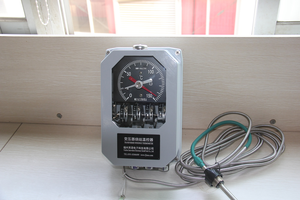
Every oil-immersed power transformer ships with an Öltemperaturanzeige (ERLEDIGT) Und, in vielen Fällen, A Wicklungstemperaturanzeige (WTI). Both instruments have served the industry for decades, yet neither delivers what modern asset management requires: a direct, real-time reading of the winding hot-spot temperature.
The OTI measures bulk oil temperature at the top of the tank — a value that lags behind actual winding temperatures by anywhere from a few minutes to over half an hour during load changes. Das WTI verbessert dies, indem es ein Wärmebild des stromabhängigen Wärmeanstiegs hinzufügt, aber das Ergebnis ist immer noch eine berechnete Schätzung, kein Messwert. Unter nicht standardmäßigen Ladeprofilen, harmonische Verzerrung, oder teilweiser Ausfall des Kühlsystems, Die WTI-Schätzung kann von der tatsächlichen Wickeltemperatur abweichen 20 °C bis 40 °C.
Diese Abweichung ist enorm wichtig. Die Transformatorisolierung folgt einer Arrhenius-Beziehung: Jeder Anstieg der anhaltenden Hot-Spot-Temperatur um 6–8 °C verkürzt die Lebensdauer der Isolierung etwa um die Hälfte (IEC 60076-2). Betrieb eines Transformators 20 Höhere Temperaturen als das WTI vermuten lässt nicht nur die Lebenserwartung sinken, sondern können auch zu einem raschen Ausfall der Isolierung innerhalb von Monaten statt Jahrzehnten führen.
1.2 Warum PT100- und Thermoelementsensoren unzureichend sind
PT100-Widerstandstemperaturfühler und Thermoelemente sind isoliert genau genug, Ihre metallische Konstruktion führt jedoch zu grundlegenden Problemen in Transformatorumgebungen:
- Elektrische Sicherheit: Ein metallischer Leiter, der von der Innenseite einer Hochspannungswicklung zu einem auf der Schalttafel montierten Instrument verläuft, birgt ein dielektrisches Risiko. Auch bei sorgfältiger Isolierung, Der Leiter stört das elektrische Feld in der Wicklung und schafft einen Potenzialpfad für Teilentladungen.
- Elektromagnetische Störungen: Starke magnetische Wechselfelder im Inneren eines unter Spannung stehenden Transformators induzieren Spannungen in metallischen Signalleitungen, Verfälschung der Temperaturmesswerte – insbesondere bei hoher Last oder Fehlerbedingungen.
- Oil compatibility: Die Standard-RTD-Konstruktion ist nicht für das unbegrenzte Eintauchen in Transformatorenöl ausgelegt; Dichtungsfehler führen im Laufe der Zeit zu Ölverschmutzung und Sensordrift.
1.3 Das Argument für die Temperaturüberwachung von Glasfaserwicklungen
![]()
Fiber optic temperature monitoring systems for oil-immersed transformers address every limitation listed above in a single technology step:
| Parameter | ERLEDIGT / WTI | PT100 RTD | Fluoreszierende Glasfaser |
|---|---|---|---|
| Measurement type | Indirekt / berechnet | Direct contact | Direct contact |
| EMI-Immunität | ✅ | ❌ | ✅ |
| Hochspannungsisolierung | ✅ | ❌ | ✅ (≥100 kV) |
| Typical accuracy | ±5 °C (geschätzt) | ±1 °C | ±1 °C |
| Real-time continuous output | ✅ | ✅ | ✅ |
| Oil submersion compatible | N / A | Beschränkt | ✅ (oil-resistant probes) |
| SCADA / Modbus integration | Beschränkt | Via transmitter | Native RS485 / Modbus RTU |
2. Drei Glasfaser-Temperaturtechnologien im Vergleich
The term “faseroptischer Temperatursensor” covers several distinct measurement principles. Choosing the wrong technology for a transformer application is one of the most common — and costly — procurement errors. Here is a plain-language comparison of the three technologies a procurement engineer is most likely to encounter.
2.1 Fluoreszierende faseroptische Sensoren (Recommended for Transformer Windings)

A Fluoreszierender faseroptischer Temperatursensor — sometimes called a fluorescence lifetime sensor — places a rare-earth phosphor crystal at the tip of a quartz fiber. The controller fires a short light pulse down the fiber; Der Kristall absorbiert den Impuls und sendet wieder ein Fluoreszenzsignal aus, dessen Abklingzeit genau ist, wiederholbare Funktion der Temperatur. Der Controller misst diese Abklingzeit und wandelt sie in einen Temperaturwert um.
Warum das für Transformatoren wichtig ist: Die Messung hängt von einem Zeitverhältnis ab, nicht auf Lichtintensität. Das bedeutet Signaldämpfung durch lange Glasfaserstrecken, Alterung des Steckverbinders, oder leichte Verschmutzungen der Faseroberfläche haben keinen Einfluss auf die Genauigkeit. Der Sensor ist wirklich selbstreferenzierend.
- Messbereich: −40 °C to +260 °C (Standard); anpassbar an +300 °C
- Genauigkeit: ±1 °C
- Auflösung: 0.1 °C
- Ansprechzeit: <1 zweite
- Sondentyp: Punktmessung – eine Sonde, ein Standort
- Best for: Direkte Hot-Spot-Messung in Transformatorwicklungen, switchgear busbars, Kabelverbindungen
2.2 Faser-Bragg-Gitter (FBG) Sensoren
FBG-Sensoren kodieren Temperaturinformationen in der reflektierten Wellenlänge eines periodischen Brechungsindexmusters, das in den Faserkern geschrieben wird. Mehrere Gitter mit unterschiedlichen Wellenlängen können auf einer einzigen Faser gemultiplext werden, making it possible to take several temperature readings along one fiber strand.
- Vorteil: Mehrpunktmessung an einer einzelnen Faser; suitable for distributed winding coverage on very large power transformers
- Limitation: The grating also responds to mechanical strain, so bending or vibration can produce spurious readings unless strain compensation is applied. The interrogator (demodulator) is significantly more complex and expensive than a fluorescent controller.
- Best for: High-channel applications where cost per point must be reduced and the installation environment is mechanically stable
2.3 Verteilte Temperaturerfassung (DTS)
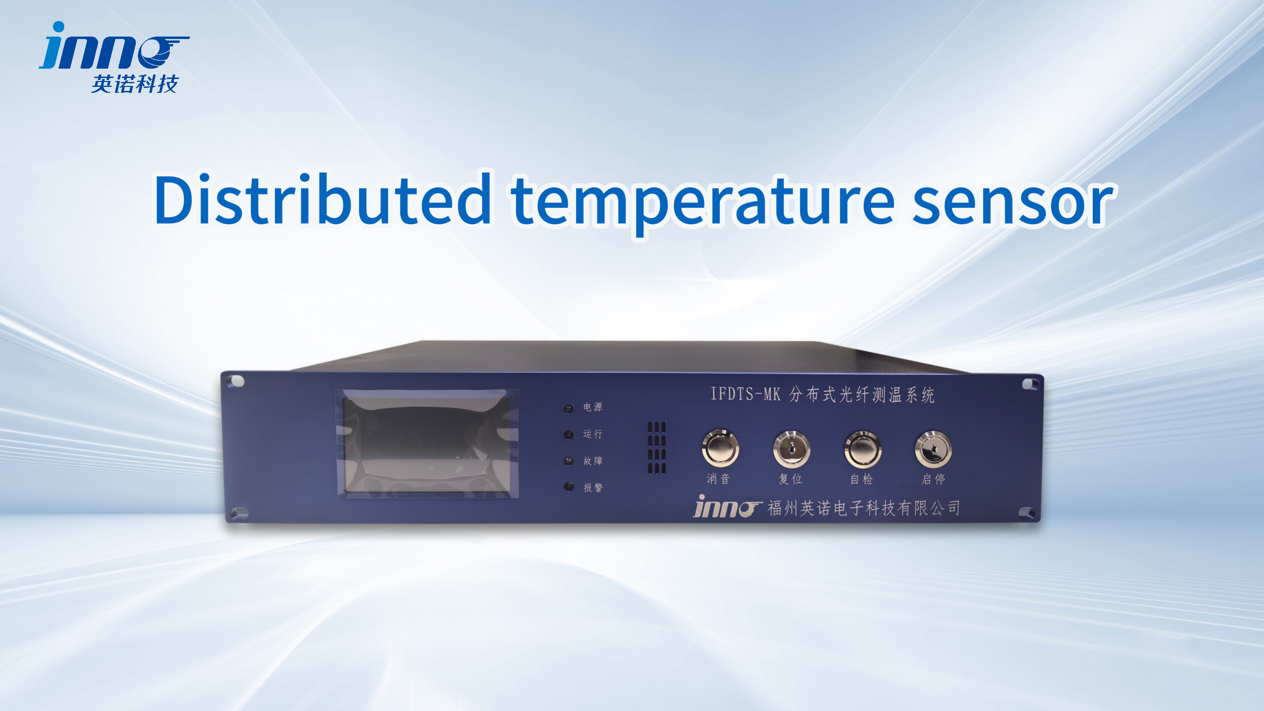
Verteilte Temperaturerfassung uses Raman or Brillouin backscattering along an ordinary single-mode or multimode fiber to produce a continuous temperature profile — thousands of measurement points along a single cable up to several kilometers long.
- Vorteil: Continuous linear coverage — ideal for cable tunnels, overhead line monitoring, Erkennung von Pipeline-Lecks
- Limitation: Spatial resolution is typically 0.5–2 m. A transformer winding hot spot occupies a few centimeters; DTS cannot resolve it. The system also requires a large interrogator unit and long averaging times to achieve acceptable accuracy.
- Best for: Power cable routes, pipeline temperature profiling — not suitable for transformer winding hot-spot detection
Technology Selection Summary
| Technologie | Measurement Mode | Transformer Winding Use | Typical Accuracy | Relative System Cost |
|---|---|---|---|---|
| Fluoreszierende Glasfaser | Punkt | ✅ Recommended | ±1 °C | Mäßig |
| FBG | Quasi-verteilt | ✅ Suitable (large transformers) | ±1–2 °C | Höher |
| DTS | Verteilt (linear) | ❌ Not suitable | ±1–2 °C over 1 M | Hoch |
3. Key Technical Specifications Explained
Supplier datasheets for faseroptische Temperaturmesssysteme can look similar on the surface. The following breakdown of each parameter helps procurement engineers read those datasheets critically and ask the right clarifying questions before committing to a purchase.
3.1 Messgenauigkeit (±1 °C)
Accuracy specifies the maximum deviation between the sensor’s displayed value and the true temperature under defined conditions. IEC 60076-2 requires that hot-spot temperature measurement uncertainty not exceed ±2 °C for compliance purposes, so a sensor rated at ±1 °C meets this requirement with margin.
What to watch for: Accuracy figures are only meaningful when accompanied by a traceable calibration certificate. Some suppliers quote ±0.5 °C or better without providing supporting calibration data. Always request a calibration certificate for at least one unit per order batch.
3.2 Messbereich (−40 °C to +260 °C-Standard)
Transformer winding temperatures under normal service rarely exceed 130 °C (Class A insulation limit per IEC 60076-2 Ist 98 °C hot-spot rise above 40 °C ambient = 138 °C total). Jedoch, emergency overload conditions, Ausfälle des Kühlsystems, or insulation degradation can push winding temperatures above 180 °C. The standard range of −40 °C to +260 °C covers all realistic scenarios with comfortable margin.
Probe tip temperature vs. controller ambient: Confirm that the probe tip rating covers the maximum winding temperature, and separately confirm that the controller enclosure rating covers the ambient temperature at its installation location (often 0–55 °C for standard industrial units).
3.3 Number of Measurement Channels
Each channel supports one faseroptischer Temperaturfühler. Selecting the correct channel count is a balance between monitoring completeness and system cost.
- Small distribution transformer (bis zu 2 MVA): 3 channels — one per phase winding top
- Medium power transformer (2–50 MVA): 6–9 channels — top and bottom of each phase winding
- Großer Leistungstransformator (50 MVA+): 9–16 channels — multiple points per winding plus tap changer and bushing positions
Unterstützung für FJINNO-Controller 1 Zu 64 Kanäle, mit benutzerdefinierten Konfigurationen für große Installationen.
3.4 Ansprechzeit (<1 Zweite)
Die Reaktionszeit definiert, wie schnell der Sensor einen Temperatursprung verfolgt. Die Reaktion in Sekundenbruchteilen erfasst beispielsweise vorübergehende Überlastereignisse, ein Durchgangsfehler, der die Wicklungen innerhalb von Millisekunden überhitzt und so den Schutzrelais aussagekräftige Daten statt verzögerter Messwerte liefert.
3.5 Dielektrische Hochspannungsisolierung (100 kV)

Dies ist die Spezifikation, die faseroptische Sensoren von allen metallischen Alternativen unterscheidet. Die Quarzfaser selbst hat keine elektrische Leitfähigkeit; kombiniert mit dem vollständig dielektrischen Sondengehäuse, Der Sensor weist keinen Leckpfad zwischen der stromführenden Wicklung und dem Messkreis auf. FJINNO-Sonden sind mit bewertet 100 kV kontinuierliche dielektrische Isolierung, covering 10 kV, 35 kV, 110 kV, Und 220 kV-Transformatorklassen.
3.6 Kommunikationsschnittstelle
Standardausgabe ist RS485 / Modbus RTU, compatible with virtually all substation SCADA platforms. For installations integrated into IEC 61850 digitale Umspannwerke, confirm whether the controller supports IEC 61850 natively or requires an external gateway. A 4–20 mA analogue output is useful for interfacing with older DCS systems.
3.7 IP Protection Rating
Controllers mounted on transformer tanks require a minimum of IP54 (dust-protected, splash-resistant). IP65 is preferred for outdoor installations or positions subject to wash-down. Probes immersed in transformer oil require oil compatibility testing per IEC 60296, not just an IP rating.
3.8 Probe Fiber Length
Der extension cable for fluorescent fiber optic temperature sensors bridges the distance between the probe tip inside the winding and the controller mounted on the tank wall or in a nearby panel. Standard lengths run 3–5 m; FJINNO supports custom fiber lengths from 0 Zu 80 m for large transformers or remote control room installations.
Specification Quick-Reference Table
| Parameter | Mindestens akzeptabel | Empfohlen | FJINNO Standard |
|---|---|---|---|
| Genauigkeit | ±2 °C | ±1 °C | ±1 °C |
| Temperaturbereich | −20 °C to +180 °C | −40 °C to +200 °C | −40 °C to +260 °C |
| Ansprechzeit | ≤5 s | ≤1 s | <1 S |
| Dielectric isolation | ≥10 kV | ≥100 kV | 100 kV |
| Kommunikation | RS485 | RS485 + optional IEC 61850 | RS485 / Modbus RTU |
| Controller IP rating | IP54 | IP65 | IP65 (available) |
| Kanäle | 3 | 6–9 (pro Transformator) | 1–64 (anpassbar) |
4. Probe Types and Installation Positions

4.1 Armored Probe for Oil-Immersed Winding Applications
Der armored fluorescent fiber optic temperature sensor for oil-immersed transformer windings features a stainless-steel protective sheath over the sensing tip and fiber cable. The armor protects the delicate quartz fiber during the winding-insertion process and provides long-term mechanical durability inside the oil tank.
When to specify: Any oil-immersed transformer where the probe must be threaded between winding layers during manufacture or field installation. The armor prevents kinking and protects against abrasion from conductor edges.
4.2 Standard Fluorescent Fiber Optic Probe
Der fiber optic temperature sensor for oil-immersed transformer winding temperature measurement in its standard form uses a PEEK or stainless-steel tip housing with the quartz fiber encased in a flexible protective jacket. This configuration suits installations where the fiber routing is smooth and the probe is installed during transformer manufacturing with careful handling procedures.
4.3 Fluorescent Fiber Optic Sensor Probes (Multi-Point Kits)
Fluorescent fiber optic temperature sensor probes are available as matched sets configured for specific transformer layouts — for example, a nine-probe kit for a three-phase, three-winding transformer with three measurement points per phase. Vorab abgestimmte Sätze vereinfachen die Beschaffung und stellen sicher, dass alle Sonden im System anhand derselben Referenz kalibriert sind.
4.4 Empfohlene Installationspositionen gemäß IEC 60076-2
IEC 60076-2 identifiziert den Wicklungs-Hotspot als den Ort, der für die Lebensdauer der Isolierung am kritischsten ist. Durch technische Best Practices werden Sonden an den folgenden Positionen platziert:
- High-voltage winding (HV): Oberseite der Wicklung (höchste Temperaturzone bei normaler Belastung) — 1 Sondenminimum; Spitze + unten bevorzugt
- Low-voltage winding (LV): Oberseite der Wicklung – 1 Sondenminimum
- Tertiär- oder Stabilisierungswicklung (if present): Oberseite der Wicklung – 1 probe
- Kern (große Einheiten): Kernoberfläche in der Nähe von Flusskonzentrationszonen – 1 Sonde optional, empfohlen für 100 MVA+
- Top-Öl-Referenz: 1 Sonde in Öl, um Glasfasermesswerte mit herkömmlichem OTI zu korrelieren
4.5 Neubau vs. Retrofit Installation
Die genaueste Installation erfolgt bei der Herstellung des Transformators, wenn Sonden zwischen Leiterschichten eingefädelt werden, bevor das Aufwickeln abgeschlossen ist. For retrofit on an existing transformer, probes are inserted through oil-fill valves, drain ports, or purpose-installed oil-tight cable glands. Retrofit accuracy is slightly lower because probe-to-conductor contact cannot be as precisely controlled, but the measurement still substantially outperforms OTI/WTI estimation.
5. Certifications and Compliance Requirements
5.1 Mandatory Product Certifications
For projects in most international markets, the following certifications are non-negotiable:
- CE-Kennzeichnung: Required for equipment sold in the European Economic Area. Covers electromagnetic compatibility (EMC Directive 2014/30/EU) and low-voltage safety (LVD 2014/35/EU). Always request the Declaration of Conformity document, not just the CE logo on the label.
- RoHS Compliance: Restriction of Hazardous Substances (EU Directive 2011/65/EU). Most utility and industrial projects globally specify RoHS compliance even outside the EU.
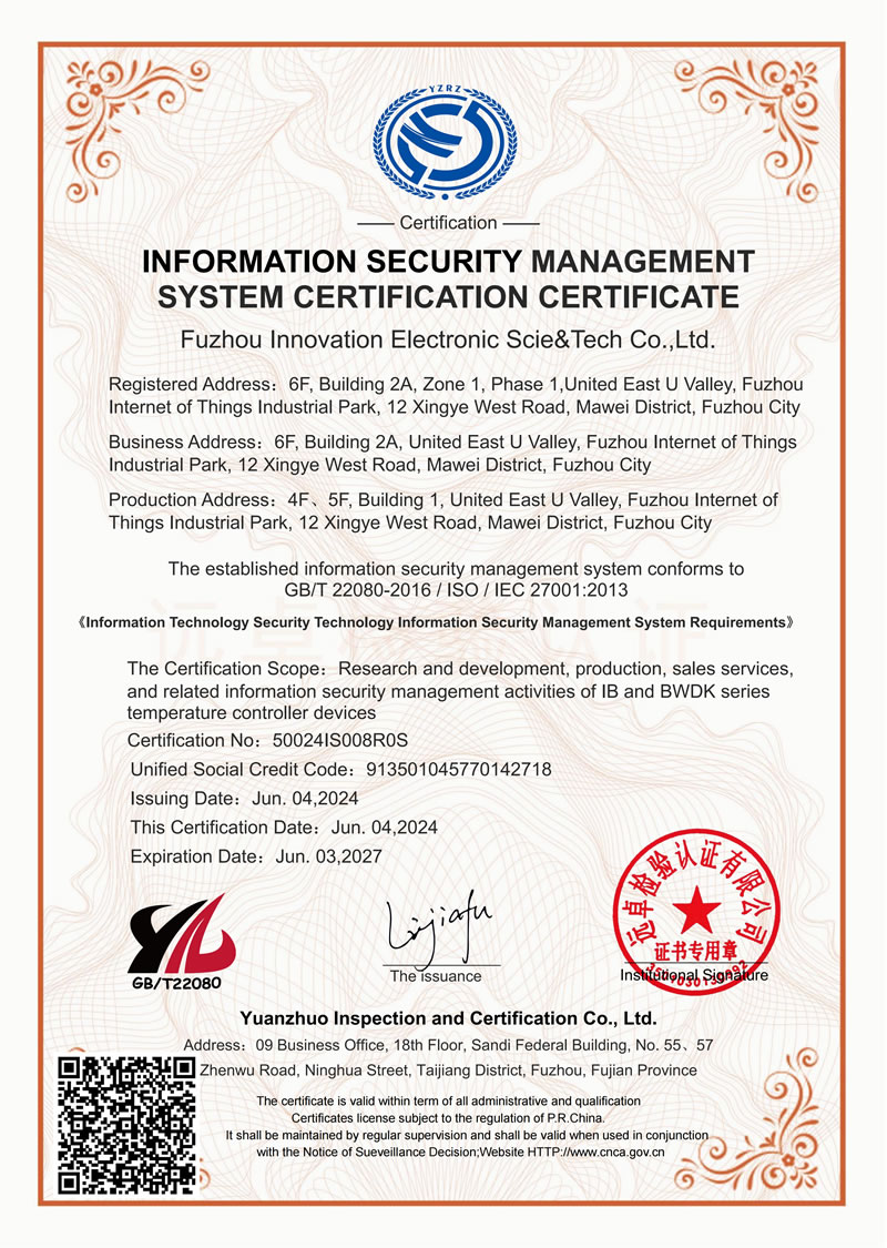
- ISO 9001 Qualitätsmanagement: Zeigt, dass der Hersteller nach einem dokumentierten Verfahren arbeitet, geprüftes Qualitätssystem. Fordern Sie das aktuelle Zertifikat mit Zertifizierungsumfang und Ablaufdatum an.
Das vollständige Zertifizierungsportfolio von FJINNO finden Sie unter https://www.fjinno.net/certificates.
5.2 Relevante Industriestandards
- IEC 60076-2: Leistungstransformatoren – Temperaturanstieg bei in Flüssigkeiten getauchten Transformatoren. Definiert Hot-Spot-Temperaturgrenzwerte und Messanforderungen, die Glasfasersysteme erfüllen müssen.
- IEC 60076-7: Belastungsleitfaden für Öl-Leistungstransformatoren. Gibt an, wie Hot-Spot-Messungen in thermische Modelle für das Überlastmanagement einfließen.
- IEC 61850: Kommunikationsnetzwerke und -systeme für die Automatisierung von Energieversorgungsunternehmen. Relevant, wenn das Temperaturüberwachungssystem in eine digitale Umspannwerksarchitektur integriert werden muss.
- IEC 60296: Flüssigkeiten für elektrotechnische Anwendungen – unbenutzte mineralische Isolieröle. Sondenmaterialien müssen mit Transformatoröl gemäß dieser Norm kompatibel sein.
5.3 How to Write Certification Requirements Into a Procurement Specification
The following language can be copied directly into a technical specification or tender document:
“The fiber optic winding temperature monitoring system shall carry CE marking with supporting Declaration of Conformity, RoHS compliance documentation, and be manufactured under an ISO 9001-certified quality management system. Products shall comply with IEC 60076-2 for measurement accuracy requirements. Communication interfaces shall support Modbus RTU as a minimum; IEC 61850 GOOSE and sampled values integration shall be provided where specified on individual transformer data sheets.”
6. Supplier Evaluation Checklist
The market for fiber optic transformer temperature monitoring systems ranges from established specialist manufacturers to resellers offering white-label products with unknown provenance. The following checklist helps procurement engineers separate credible suppliers from those carrying commercial risk.
6.1 Technical Capability
- Does the supplier manufacture the fluorescent probe tip in-house, or source it from a third party?
- Can they provide a traceable calibration certificate for each sensor?
- Do they have documented oil-immersion soak test data (Minimum 1,000 hours in transformer oil per IEC 60296)?
- Can they supply probe installation drawings dimensioned to fit your specific transformer manufacturer’s winding geometry?
- Do they support custom channel counts, Faserlängen, und Kommunikationsprotokolle?
6.2 Delivery and Logistics
- Standard lead time for a 10-unit order (benchmark: 4–8 weeks for custom configurations)
- Availability of safety stock for common configurations to cover urgent replacement needs
- Experience with export documentation for your import jurisdiction
- OEM- und ODM-Fähigkeit, wenn Sie Marken- oder integrierte Produkte benötigen
6.3 After-Sales Support
- Garantiezeitraum – fordern Sie mindestens an 24 Monate auf Sonde und Controller
- Können einzelne Sonden ausgetauscht werden, ohne den kompletten Controller auszutauschen??
- Ist eine englischsprachige technische Dokumentation verfügbar? (Installationshandbuch, Modbus-Registerkarte, Schaltpläne)?
- Ist eine Ferninbetriebnahmeunterstützung per Videoanruf oder TeamViewer verfügbar??
- Was ist der Eskalationspfad für einen Garantieanspruch??
6.4 Zehn Fragen, die Sie jedem in die engere Auswahl kommenden Lieferanten stellen sollten
- Wie hoch ist die kontinuierliche dielektrische Isolationsspannung der Sonde von der Spitze bis zum Anschluss??
- Können Sie für jede Sonde in meiner Bestellung ein individuelles Kalibrierzertifikat bereitstellen??
- Welches Sondengehäusematerial wird verwendet?, und wie wurde die Ölverträglichkeit bestätigt??
- Was ist die maximale Glasfaserkabellänge, die Sie ohne Signalverstärker liefern können??
- Welche Kommunikationsprotokolle unterstützt der Controller nativ??
- Welche separaten Garantiebedingungen gelten für die Sonde im Vergleich zum Controller??
- Können Sie Referenzkontakte bei einem Transformator-OEM oder Versorgungsunternehmen bereitstellen, bei dem Ihr System eingesetzt wurde? 110 kV oder höher?
- Können Sie die mechanische Zeichnung der Sonde zur Überprüfung durch unseren Transformatorhersteller zur Verfügung stellen??
- Was ist Ihre Standardvorlaufzeit für eine Bestellung von 20 Einheiten?, und verfügen Sie über Pufferbestände??
- Unterstützen Sie Werksabnahmetests durch Dritte in Ihrer Einrichtung??
7. Common Procurement Mistakes to Avoid
Die folgenden Fehler tauchen in Projekt-Post-Mortems wiederholt auf. Beides lässt sich bereits in der Spezifikationsphase verhindern.
❌ Fehler 1 — Angabe von DTS für die Wicklungs-Hot-Spot-Messung
Verteilte Temperaturerfassungssysteme eignen sich für Kabeltrassen und Rohrleitungen, Nicht für heiße Stellen in der Transformatorwicklung. The 0.5–2 m spatial resolution of DTS cannot locate a hot spot that occupies a few conductor turns. Specify point-type fluoreszierende faseroptische Sensoren for winding applications.
❌ Fehler 2 — Selecting channel count based on budget rather than measurement strategy
Under-instrumenting a transformer — installing only one probe on a three-phase winding, for example — saves money on day one and creates a significant blind spot. If the hot phase is not monitored, the system gives false comfort. Follow the IEC 60076-2 minimum positions described in Section 4.4.
❌ Fehler 3 — Ignoring communication protocol compatibility
A sensor that arrives on site with only a proprietary ASCII protocol cannot be integrated into a Modbus-based SCADA without a custom gateway. Confirm the exact protocol, register map, and baud rate settings before purchasing. Request a Modbus register map as part of the quotation package.
❌ Fehler 4 — Accepting accuracy claims without calibration evidence
An uncertified ±0.5 °C claim is worth less than a certified ±1 °C claim. For critical protection applications, require per-unit calibration certificates traceable to a national metrology standard.
❌ Fehler 5 — Purchasing from a reseller with no direct access to the manufacturer
If the selling entity cannot answer technical questions about probe construction, oil soak test data, or installation procedure, they are unlikely to support you effectively when a problem arises in service. Verify that your point of contact has direct access to engineering staff at the actual manufacturing facility.
❌ Fehler 6 — Overlooking probe oil compatibility
A probe rated to 260 °C thermisch dennoch vorzeitig ausfallen, wenn sein Gehäusematerial Transformatoröl aufnimmt, schwillt an, und delaminiert den Sensorkristall. Fragen Sie gezielt nach, ob die Sonde gemäß IEC in Transformator-Mineralöl getestet wurde 60296, und wie lange.
8. Fallstudien aus der Praxis

8.1 Fluoreszierende faseroptische Temperaturmessung in ölgetränkten Transformatorwicklungen
FJINNOs dokumentierte Fallstudie zu Fluoreszierende faseroptische Temperaturmessung von in Öl getauchten Transformatorwicklungen zeigt, wie während der Fertigung installierte Punktsensoren kontinuierliche Hot-Spot-Daten liefern, die direkt in das Wärmeschutzrelais des Transformators eingespeist werden. Die Installation umfasst Hochspannung, low-voltage, und Neutralpunktpositionen, wobei die Faserlängen durch öldichte Kabelverschraubungen zu einem externen Mehrkanal-Controller geführt werden.
Key outcomes documented in the case study include detection of a localized cooling obstruction that raised one phase winding 18 °C above the OTI reading — a discrepancy that would have been invisible without direct winding measurement.
8.2 110 kV Hybrid-Insulated Transformer Online Monitoring in Substations
Der 110 kV hybrid-insulated oil transformer online monitoring installation case describes integration of a 12-channel fiber optic winding temperature system with the substation’s IEC 61850 communication architecture. The controller’s Modbus output feeds a protocol gateway, which presents temperature data as IEC 61850 logical nodes to the substation automation system.
This installation illustrates the importance of confirming communication protocol compatibility before procurement — the project required one additional protocol converter that would have been unnecessary had IEC 61850 native support been specified from the outset.
9. How FJINNO’s Products Fit This Application

FJINNO — Fuzhou Innovation Electronic Science & Technologie Co., Ltd. — has manufactured fluoreszierende faseroptische Temperatursensoren and complete Temperaturüberwachungssysteme für Transformatoren for power utilities, Transformator-OEMs, and EPC contractors across more than 20 Länder. The product range specifically designed for oil-immersed transformer applications includes:
- Faseroptischer Temperaturfühler — Standard point-type fluorescent probe, 1–64 Kanäle, −40 °C to +260 °C, ±1 °C, 100 kV isolation, RS485/Modbus RTU, customizable fiber length 0–80 m
- Gepanzerter fluoreszierender faseroptischer Temperatursensor für in Öl getauchte Transformatorwicklungen — Mechanically protected probe for installation into energized or factory-wound transformer coils
- Fiber Optic Temperature Sensor for Oil-Immersed Transformer Winding Temperature Measurement — Application-specific configuration with oil-compatible housing materials and matching controller
- Fluoreszierende faseroptische Temperatursensorsonden — Multi-probe kits matched to specific transformer winding layouts
- Verlängerungskabel für fluoreszierende faseroptische Temperatursensoren — Custom-length fiber extension for routing from winding to external controller
- Fiber Optic Temperature Measurement System for Oil-Immersed Transformers — Complete integrated system including controller, Sonden, Kabel, Montagematerial, and software
The complete Lösung zur Überwachung der Transformatortemperatur covers system design, probe placement guidance, controller configuration, and SCADA integration support. Procurement teams can view the full transformer monitoring solutions portfolio for an overview of all available configurations.
FJINNO holds CE, RoHS, and ISO 9001 certifications — all verifiable at https://www.fjinno.net/certificates. Der services page details OEM, ODM, individuelles Design, and technical support offerings.
To request a project-specific configuration and quotation, use the Holen Sie sich ein Angebot form or contact the technical sales team directly.
10. Häufig gestellte Fragen
Q1: What is the difference between an OTI and a winding temperature indicator, and why are both inadequate for hot-spot monitoring?
An OTI (Öltemperaturanzeige) measures the temperature of bulk oil at the transformer tank top — a value that lags actual winding temperature by up to 40 °C under transient load. A WTI (Wicklungstemperaturanzeige) improves on this by adding a simulated thermal image driven by load current, but the result is still a calculation, not a measurement. Both instruments assume uniform thermal behavior that deviates significantly under non-standard loading, cooling system faults, or harmonic distortion. Direkt faseroptische Wicklungstemperatursensoren measure actual conductor temperatures at defined positions, eliminating estimation error entirely.
Q2: Can a fluorescent fiber optic sensor be installed in an existing transformer without draining the oil?
Retrofit installation without full oil drain is possible in transformers equipped with suitable access ports — oil-fill valves, drain ports, or purpose-installed oil-tight cable glands. The probe is inserted through the port using a flexible guide tube and positioned at the target winding location. Measurement accuracy with retrofit probes is slightly lower than factory-installed probes because exact probe-to-conductor contact cannot be guaranteed, but the reading still substantially outperforms OTI/WTI estimation. Contact FJINNO’s technical team for guidance specific to your transformer type.
Q3: How many measurement channels does a typical 40 MVA power transformer require?
A 40 MVA three-phase two-winding transformer typically warrants 6 channels as a minimum: one probe at the top of each HV phase winding and one at the top of each LV phase winding. Adding probes at the winding bottoms increases the count to 12 but provides a complete thermal profile that supports dynamic loading calculations per IEC 60076-7. The optimal channel count depends on transformer voltage class, Kritikalität, and whether the system feeds a thermal model or a simple alarm function.
Q4: What does “100 kV dielectric isolation” mean in practical terms?
It means the quartz fiber and probe housing present no conductive path between the measurement point (inside a live transformer winding) and the signal-processing electronics in the controller. Der 100 kV figure is the withstand voltage tested on the complete probe-to-controller assembly. In der Praxis, this allows the probe to be placed in direct contact with live conductors in transformers rated up to 220 kV without any risk of leakage current, Erdschluss, or electric field distortion at the probe location.
F5: Is fluorescent fiber optic sensing affected by transformer oil aging or contamination?
The fluorescent crystal at the probe tip is hermetically sealed inside its housing and does not contact the oil directly. The quartz fiber transmission characteristics are also unaffected by external media. Long-term oil aging or contamination therefore does not degrade sensor accuracy. The probe housing material must be compatible with transformer oil per IEC 60296 — FJINNO specifies oil-compatible materials for all transformer probe variants and conducts immersion testing to verify long-term compatibility.
F6: Can the fiber optic temperature monitoring system integrate with an IEC 61850 substation automation system?
FJINNO controllers provide native RS485/Modbus RTU output. Integration into IEC 61850 architectures is achieved via a Modbus-to-IEC 61850 protocol gateway, which presents temperature data as logical nodes within the substation’s communication infrastructure. Where IEC 61850 native support is required without an external gateway, discuss this requirement explicitly with FJINNO’s technical team at the specification stage.
F7: How long do fiber optic probes last inside transformer oil?
Fluorescent fiber optic probes designed for oil-immersed applications are rated for service lives aligned with transformer overhaul intervals — typically 20–25 years. The optical measurement principle has no wear mechanism, and the quartz fiber does not degrade in transformer oil. The main life-limiting factor is mechanical integrity of the probe housing and fiber routing under thermal cycling. Correct installation practice — avoiding sharp bends in the fiber and protecting the cable exit from abrasion — is the primary determinant of service life.
F8: What information should be included in a Request for Quotation (RFQ) for a fiber optic transformer temperature monitoring system?
A well-structured RFQ should include: transformer rating (MVA, Spannungsklasse, number of windings), number of probes required and their target installation positions, required fiber length from winding to controller, controller mounting location and available power supply, communication protocol required (Modbus RTU, 4–20 mA, IEC 61850), accuracy and range requirements, environmental conditions at the controller location (Temperatur, Luftfeuchtigkeit, IP class), relevant certifications (CE, RoHS, usw.), and order quantity. The more detail provided, the more accurate and comparable the quotations received will be.
F9: Is there a risk of the probe affecting transformer winding insulation?
NEIN, when correctly specified and installed. The probe tip is a small-diameter, all-dielectric element. It introduces no metallic conductor into the winding insulation structure and no electric field distortion. The probe housing materials are selected for compatibility with the winding insulation system (paper/oil for oil-immersed transformers, epoxy-resin for dry-type). FJINNO coordinates with transformer OEMs to confirm probe geometry and material compatibility before supply.
F10: What after-sales support does FJINNO provide for transformer fiber optic monitoring systems?
FJINNOs after-sales services enthalten: detailed installation and commissioning documentation, Modbus register maps and wiring diagrams, remote commissioning support via video call, Fehlerbehebung und Diagnose, warranty replacement for faulty components, and technical consultation throughout the product lifecycle. For large installations, on-site commissioning support can be arranged. Contact the technical support team for project-specific arrangements.
Haftungsausschluss
The information contained in this article is provided for general guidance purposes only and reflects the state of knowledge and product specifications available at the time of writing. Technische Spezifikationen, product configurations, Zertifizierungen, and service terms are subject to change without notice as part of ongoing product development. Actual product performance in any specific application depends on correct product selection, proper installation, entsprechende Systemkonfiguration, and operating conditions consistent with the product’s rated environment.
Nothing in this article constitutes professional engineering advice, a binding product warranty, or a contractual commitment. All specifications must be confirmed through formal quotation and purchase order documentation before reliance in design or procurement decisions. Compliance with applicable local codes, Standards, and regulatory requirements remains the sole responsibility of the purchaser and installer.
FJINNO (Fuzhou Innovation Electronic Science & Technologie Co., Ltd.) reserves the right to modify product specifications and discontinue models at any time. For current specifications and availability, Kontakt https://www.fjinno.net/contact or submit an enquiry via https://www.fjinno.net/get-a-quote/.
Third-party standards referenced in this article (IEC 60076-2, IEC 60076-7, IEC 61850, IEC 60296, usw.) are the property of their respective issuing bodies. Readers should consult the current versions of those standards directly for authoritative technical requirements.

Faseroptischer Temperatursensor, Intelligentes Überwachungssystem, Verteilter Glasfaserhersteller in China
 |
 |
 |