 INNO faseroptische Temperatursensoren ,Temperaturüberwachungssysteme.
- Keine elektromagnetischen Störungen: Optical fiber carries light, not electricity — it is completely immune to EMI/RFI, making it the only reliable choice for high-voltage switchgear and transformer hotspot monitoring.
- Pinpoint accuracy at extreme conditions: Fluorescent point sensors achieve ±1 °C accuracy aus −40 °C bis +260 °C, with a response time under 1 second and a probe as slim as 2–3 mm.
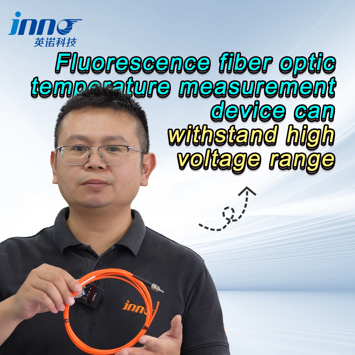
- Electrically safe in 100 kV+ environments: Probes are fully insulating and rated for voltages well above 100 kV — no grounding issues, no creepage paths.
- One transmitter, bis zu 64 Kanäle: Eine Single Glasfaser-Temperaturtransmitter handles 1–64 fluorescent fiber channels simultaneously, dramatically reducing hardware costs.
- Maintenance-free for 25+ Jahre: Keine beweglichen Teile, no consumables, no periodic calibration required under normal operating conditions.
- Scalable architecture: RS485 communication integrates directly with SCADA, DCS, und Automatisierungsplattformen für Umspannwerke; all parameters are customizable.
- Proven across critical industries: Deployed in power transmission, Rechenzentren, petrochemische Anlagen, rail traction systems, and industrial furnaces worldwide.
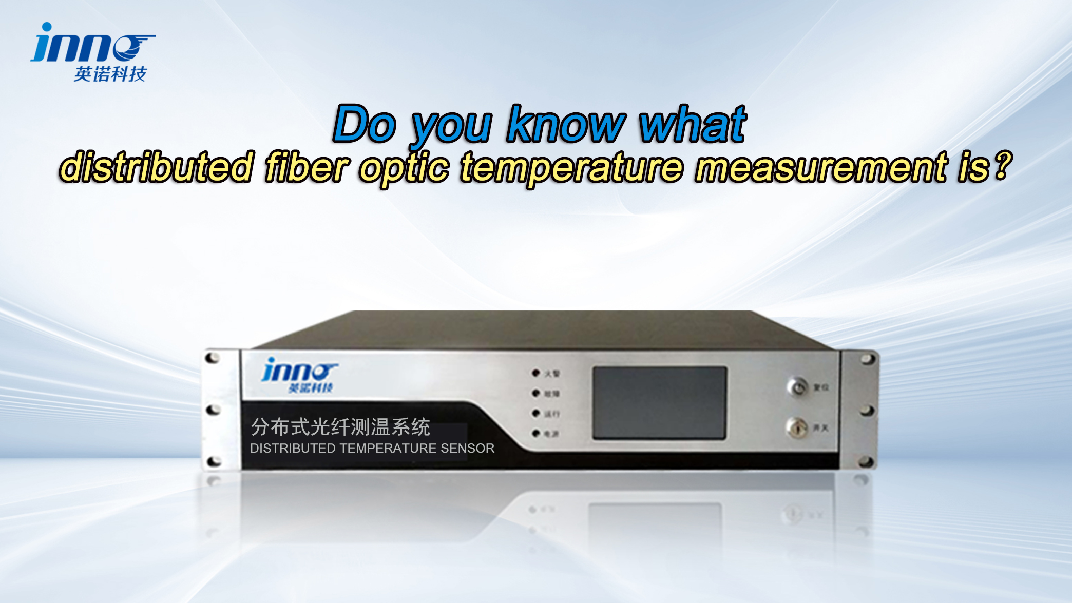
1. Was ist ein Faseroptisches Temperaturmesssystem?

A faseroptisches Temperaturmesssystem is an instrumentation platform that uses light-transmitting optical fibers — rather than metal conductors — to detect and report temperature at one or more points in real time. The sensor probe converts a physical temperature into an optical signal, which travels back along the fiber to a dedicated Glasfaser-Temperaturtransmitter (also called a signal conditioner or interrogator unit) that decodes the signal and outputs a temperature reading.
Because the sensing element is made entirely of dielectric materials, the probe and fiber cable carry no electrical current whatsoever. This distinguishes the technology fundamentally from thermocouples, RTDs, and thermistors, all of which require an electrical circuit to function and are therefore susceptible to ground loops, EMI, and electrical hazards in high-voltage installations.
The system is available in two primary sensing architectures: fluorescent point temperature sensing Und verteilte faseroptische Temperaturmessung (DTS). Both share the same core benefit of electrical isolation, but serve different measurement objectives.
2. How Does It Compare to Traditional Temperature Sensors?
Traditional sensors — thermocouples, PT100-RTDs, and bimetallic devices — have served industry for over a century. Jedoch, they face critical limitations in modern electrical and industrial environments that fiber optic technology directly resolves.
| Parameter | Thermoelement / FTE | Fluoreszierender faseroptischer Sensor |
|---|---|---|
| EMI-Immunität | None — signal degrades near HV equipment | Complete — no electrical signal in the fiber |
| Elektrische Isolierung | Requires isolation barriers | Inherently insulating; bewertet >100 kV |
| Genauigkeit | ±0.5–2 °C (with drift over time) | ±1 °C, stable over 25+ Jahr Lebensdauer |
| Ansprechzeit | 1–10 seconds typical | <1 zweite |
| Sondendurchmesser | 4–10 mm typical | 2–3 mm (custom available) |
| Wartung | Periodic recalibration required | Keine erforderlich |
| Multi-channel from one unit | Typically 1–8 channels per transmitter | 1–64 channels per transmitter |
3. How Does a Fiber Optic Temperature Measurement System Work?
Prinzip des Fluoreszenzzerfalls

In fluoreszierende faseroptische Temperatursensoren, the probe tip contains a rare-earth phosphor compound. The interrogator unit pulses a precisely controlled excitation light down the fiber. The phosphor absorbs this energy and re-emits it as fluorescence. Critically, the duration of that fluorescence — known as the fluorescence lifetime or decay time — is a repeatable, predictable function of temperature. The interrogator measures this decay time and converts it directly into a temperature value.
Because the measurement depends on a time interval rather than a voltage level or light intensity, Es ist von Natur aus immun gegen Faserbiegeverluste, connector contamination, and electromagnetic noise — all of which would corrupt a voltage-based electrical sensor.
Verteilt (Raman / Brillouin) Prinzip
In distributed fiber optic temperature sensing systems, a laser pulse is launched into a standard single-mode or multimode fiber. As light propagates, it scatters at molecular level. The backscattered Raman or Brillouin components shift in frequency and amplitude in direct proportion to the local temperature at every meter along the fiber. By measuring the time it takes for backscattered light to return, the system assigns a precise temperature to every spatial position along the cable — turning a single fiber into thousands of temperature sensors simultaneously.
4. Fluorescent Point Sensing vs. Verteilte faseroptische Temperaturmessung
| Besonderheit | Fluorescent Point Sensing | Verteilte Glasfaser (DTS) |
|---|---|---|
| Messtyp | Discrete hotspot points | Continuous profile along fiber |
| Typical range | −40 °C bis +260 °C | −40 °C bis +300 °C (system-dependent) |
| Spatial coverage per fiber | Bis zu 80 M; 1–64 discrete points | Bis zu 30 km+ |
| Best applications | Transformatorwicklungen, switchgear busbars, Motorlager | Erdkabel, Pipelines, Tunnelbranderkennung |
| System cost | Lower per-point cost | Höhere Anschaffungskosten; lower per-meter cost at scale |
5. What Are the Main Components of the System?
- Fluoreszierende faseroptische Sonde (sensor head): The physical tip inserted at the measurement point. Contains the phosphor sensing element encapsulated in a slim, electrically insulating sheath (2–3 mm Durchmesser). Custom shapes and materials are available for specific installation geometries.
- Optical fiber cable: The light-transmission medium connecting probe to transmitter. Standard single-mode or multimode fiber; maximum run of 80 m for fluorescent systems. Armored, PTFE, or high-temperature jacket variants are available.
- Faseroptischer Temperaturtransmitter (Vernehmer): The signal processing unit. Houses the light source, Fotodetektoren, timing electronics, and microprocessor. Outputs calibrated temperature values via RS485 or other interfaces. One unit supports 1–64 channels.
- Software / SCADA-Integration: Host-side software or Modbus/RS485 register mapping allows direct integration into existing DCS, SCADA, oder Anlagenautomatisierungssysteme. No proprietary middleware is required.
6. Fluoreszierender faseroptischer Temperatursensor — Full Technical Specifications
| Parameter | Spezifikation |
|---|---|
| Sensing method | Fluoreszenzlebensdauer (phosphor decay) — point measurement |
| Messgenauigkeit | ±1 °C |
| Temperaturmessbereich | −40 °C bis +260 °C |
| Ansprechzeit | <1 zweite |
| Maximum fiber cable length | 0 – 80 M |
| Probe outer diameter | 2–3 mm (custom diameters available) |
| Elektrische Isolierung | Fully insulating; no conductive path |
| High-voltage withstand | >100 kV (anpassbar) |
| Channels per transmitter | 1 – 64 (scalable) |
| Kommunikationsschnittstelle | RS485 (Modbus RTU); other interfaces customizable |
| Lebensdauer | >25 years under normal conditions |
| Wartungsbedarf | None — maintenance-free design |
All parameters can be customized. Contact FJINNO to discuss specific project requirements.
7. Why Is Fiber Optic the Only EMI-Immune Temperature Sensing Technology?
Every electrical temperature sensor generates a small voltage or resistance signal that must be transmitted over metal conductors. In high-voltage switchyards, transformer rooms, and industrial drives, these conductors act as receiving antennas, picking up interference from switching transients, busbar current, and radio-frequency fields. The resulting measurement error can be several degrees Celsius — or cause complete signal loss — rendering the measurement unreliable for protection or condition monitoring decisions.
A Fluoreszierender faseroptischer Temperatursensor transmits only light. Light is not affected by electric or magnetic fields. No matter how intense the surrounding electromagnetic environment — whether it is a 500 kV transformer or a high-current arc furnace — the optical signal arriving back at the transmitter is identical to the signal that left it, carrying an accurate temperature measurement every single time.
This is not a marginal improvement over shielded cable or isolation amplifiers; it is a fundamentally different physical mechanism that eliminates the interference problem entirely.
8. How Does the System Perform in High-Voltage Environments Above 100 kV?
Standard metallic sensors cannot be placed directly on live high-voltage conductors without an engineered isolation barrier, because doing so would create a conductive path from the live part to ground through the sensor cable and instrumentation wiring. This is both a personnel safety hazard and a source of measurement error via leakage currents.
Der faseroptischer Temperaturfühler is manufactured entirely from non-conductive materials: the sensing tip, the fiber core, the cladding, and the cable sheath are all dielectric. There is no metallic element in the sensing chain at any point between the probe tip and the transmitter housing. The result is a probe that can be embedded directly in a transformer winding, clamped onto a live 110 kV busbar, or routed through a GIS enclosure without any grounding concern or creepage risk.
FJINNO probes are rated for voltage withstand levels exceeding 100 kV. Custom designs for ultra-high-voltage (UHV) applications above 500 kV are available on request.
9. How Is the System Applied in Power Transformers?
Winding Hotspot Monitoring
The most critical measurement in any oil-immersed or dry-type transformer is the winding hotspot temperature. IEC and IEEE standards specify thermal limits based on this temperature; exceeding them accelerates insulation aging exponentially. Fluorescent probes are embedded directly between winding conductors during manufacturing or retrofit installation, providing continuous hotspot data that thermal models based on top-oil temperature alone cannot reliably deliver.
Top-Oil and Ambient Reference
Additional channels on the same transmitter monitor top-oil temperature and ambient air temperature, providing the complete thermal picture needed for dynamic load management and remaining-life calculations.
Dry-Type Transformer Coil Temperature
In cast-resin dry-type transformers, probes are embedded in the resin coils at the design stage. Eine Single Glasfaser-Temperaturüberwachungssystem with four to eight channels covers all three phases with redundancy, replacing traditional PT100 sensors that require grounding rings and are sensitive to EMI from the winding currents.
10. How Is the System Used in Medium-Voltage Switchgear?
Sammelschienenverbindungen, Kabelendverschlüsse, and draw-out contacts inside switchgear panels are common sites for resistive heating caused by loose connections, Kontaktverschleiß, oder Überlastung. Left undetected, a thermal hotspot at a busbar joint progresses from mild overheating to insulation carbonization to a catastrophic arc flash event.
A fiber optic temperature monitoring system for switchgear places multiple probes — typically one per phase per critical joint — across all panels in a switchroom. Because the probes are passive and dielectric, they can be installed on live equipment during a normal maintenance window without a full outage. The transmitter continuously compares readings across phases; an asymmetric temperature rise on a single phase is a reliable early indicator of a developing fault, enabling targeted maintenance before failure occurs.
11. What Other Industries Rely on Fiber Optic Temperature Measurement?

- Rechenzentren: Continuous monitoring of server rack hotspots, busway temperature, and UPS battery banks without the grounding complications of metallic sensors in dense cable environments.
- Öl & gas and petrochemical: Probe chemically inert materials withstand corrosive media; distributed systems monitor pipeline integrity and storage tank stratification over kilometers.
- Rail and traction: Motor winding temperature in rolling stock traction drives; high EMI from inverter systems makes fiber optic the only practical point sensor technology.
- Industrial furnaces and kilns: The −40 °C to +260 °C range covers most process heating applications; custom probes extend to higher temperature ranges for specialized furnace applications.
- Medical and MRI: The complete absence of metallic and conductive elements makes fluorescent probes safe for use inside MRI scanner bores where ferromagnetic materials are prohibited.
12. How Do You Select the Right Faseroptisches Temperaturmesssystem?

- Define measurement objectives: If you need temperature at specific, known hotspot locations — winding conductors, Kabelendverschlüsse, busbar contacts — a fluorescent point temperature measurement system is the correct choice. If you need a continuous temperature profile over tens or hundreds of meters, a distributed DTS system is more appropriate.
- Determine channel count: Count the number of individual measurement points required. A single transmitter supports up to 64 fluorescent channels. Für größere Installationen, multiple transmitters can be networked over RS485.
- Specify voltage class: Confirm the live-voltage level at each probe installation point. Standard probes are rated above 100 kV. For UHV applications, specify the voltage class explicitly when ordering.
- Consider probe geometry: The slim 2–3 mm probe diameter fits most standard winding slot and cable termination geometries. Non-standard shapes — flat, flexibel, potted — are available for custom installations.
- Plan integration: Confirm the communication protocol required by your SCADA or DCS. RS485/Modbus RTU is standard; Ethernet, Profibus, and other protocols are available as options.
13. What Communication Interfaces and Integration Options Are Available?
The standard Glasfaser-Temperaturtransmitter communicates via RS485 using the Modbus RTU protocol, which is natively supported by virtually every industrial SCADA, DCS, and building management system on the market. The register map provides real-time temperature values, Alarmstatus, and channel identification for every connected probe.
For projects requiring Ethernet/TCP, Profibus DP, CAN bus, 4–20 mA analog outputs, or dry-contact relay alarm outputs, FJINNO offers customized transmitter variants. All specifications — including baud rate, Modbus address, Alarmschwellen, and channel configuration — are set via software or front-panel interface and do not require hardware modification.
14. Spitze Fiber Optic Temperature Measurement System Manufacturers

The following companies are recognized industry leaders in the design and manufacture of fiber optic temperature measurement systems. Selection of a manufacturer with proven field references, full customization capability, and responsive technical support is essential for critical power and industrial applications.
🥇 #1 — Fuzhou Innovation Electronic Scie&Tech Co., Ltd. (FJINNO)
| Gegründet | 2011 |
| Hauptsitz | Liandong U Grain Networking Industrial Park, NEIN. 12 Xingye West Road, Fuzhou, Fujian, China |
| Spezialisierung | Fluoreszierende faseroptische Temperatursensoren, Verteilte Glasfasersysteme, Transformator & Schaltanlagenüberwachung, OEM/ODM custom manufacturing |
| Key advantage | Factory-direct pricing, 1–64 channel scalable transmitters, full customization, global export experience |
| Webseite | www.fjinno.net |
| web@fjinno.net | |
| WhatsApp / WeChat / Telefon | +86 135 9907 0393 |
| 3408968340 |
🥈 #2 — Fuzhou Huaguang Tianrui Optoelectronics Technology Co., Ltd.
| Gegründet | 2016 |
| Hauptsitz | Fuzhou, Fujian, China |
| Spezialisierung | Faseroptische Sensorik, optoelectronic measurement systems, power grid temperature monitoring |
| Key advantage | Focus on optoelectronic R&D; serves domestic Chinese utility sector |
15. Why Is FJINNO the Leading Choice for Fiber Optic Temperature Measurement?
- Over a decade of field-proven performance: FJINNO has been designing and manufacturing faseroptische Temperaturmesssysteme seit 2011. Systems installed in the first years of operation continue to perform within specification today, validating the 25+ year service life claim with real operating history rather than accelerated-aging projections alone.
- Factory-direct customization at scale: As both designer and manufacturer, FJINNO can modify probe geometry, Faserlänge, Nennspannung, Kanalanzahl, housing material, Kommunikationsprotokoll, and alarm configuration without the lead times or costs associated with reseller intermediaries. This makes FJINNO the practical choice for both standard product orders and fully engineered custom systems.
- Comprehensive application engineering support: FJINNO engineers provide documentation, integration guidance, and installation drawings for transformer OEMs, EPC-Auftragnehmer, and end-user utilities — not just a product datasheet. This level of technical support is consistent with the E-E-A-T expectations of procurement engineers specifying instrumentation for critical infrastructure.
16. Häufig gestellte Fragen (FAQ)
Common questions about faseroptische Temperaturmesssysteme, answered for engineers, Beschaffungsteams, and facility managers.
Q1: What is a fiber optic temperature measurement system used for?
A faseroptisches Temperaturmesssystem is used to monitor temperature at critical points in electrical and industrial equipment — including power transformer windings, switchgear busbars, Kabelverbindungen, Motorlager, and industrial process lines — where traditional metallic sensors cannot operate reliably due to electromagnetic interference or high-voltage hazards.
Q2: What is the difference between a fiber optic temperature sensor and a fiber optic temperature transmitter?
Der faseroptischer Temperatursensor (probe) is the physical element placed at the measurement point. It detects temperature and converts it into an optical signal. Der Glasfaser-Temperaturtransmitter is the instrument unit that sends light to the probe, empfängt das Rücksignal, and outputs a calibrated temperature reading via RS485 or other interfaces. The two components work together as a complete Glasfaser-Temperaturüberwachungssystem.
Q3: Was ist ein fluoreszierender faseroptischer Temperatursensor??
A Fluoreszierender faseroptischer Temperatursensor is a point-measurement sensor that uses a phosphor compound at the probe tip. Bei Anregung durch einen Lichtimpuls vom Sender, the phosphor emits fluorescence whose decay time is a direct and stable function of temperature. This method delivers ±1 °C accuracy with no drift over the sensor’s service life, Dies macht es zur bevorzugten Wahl für Überwachung der Transformatorwicklungstemperatur Und Hotspot-Erkennung in Schaltanlagen.
Q4: How does a distributed fiber optic temperature sensor differ from a point sensor?
A Verteilter faseroptischer Temperatursensor (DTS) turns an entire fiber cable into a continuous sensing element, measuring temperature at every meter along its length — covering distances of several kilometers from a single instrument. It is used for applications such as underground cable temperature monitoring, Erkennung von Pipeline-Lecks, and tunnel fire detection. A fluorescent point sensor, im Gegensatz dazu, measures temperature at one specific location with higher accuracy and faster response, making it better suited for hotspot monitoring in discrete equipment like transformers and switchgear panels.
F5: What industries use fiber optic temperature monitoring systems?
Glasfaser-Temperaturüberwachungssysteme are deployed across power transmission and distribution (Transformatoren, GIS, Schaltanlage), Rechenzentren, oil and gas processing, rail traction drives, industrial furnaces, and medical imaging (MRT). Any environment combining high electrical voltages, starke elektromagnetische Felder, or chemically aggressive media — where metallic sensors would be unsafe or unreliable — is a natural application for a faseroptisches Temperaturmesssystem.
F6: Can a fiber optic temperature monitoring system integrate with SCADA or DCS platforms?
Ja. Der Glasfaser-Temperaturtransmitter communicates via RS485 using the Modbus RTU protocol, which is natively supported by virtually all industrial SCADA, DCS, und Umspannwerkautomatisierungssysteme. Custom communication interfaces — including Ethernet/TCP, Profibus DP, 4–20 mA analog outputs, and relay alarm contacts — are available, das erlauben Glasfaser-Temperaturüberwachungssystem to integrate seamlessly into any existing control architecture.
F7: What is the best fiber optic temperature sensor for transformer winding hotspot monitoring?
Der Fluoreszierender faseroptischer Temperatursensor is the industry-standard choice for Hotspot-Überwachung der Transformatorwicklung. Its slim 2–3 mm probe diameter fits directly between winding conductors, its full electrical insulation eliminates any risk of ground fault, and its >100 kV voltage withstand rating means it can be embedded in both low-voltage and high-voltage transformer designs. Eine Single Glasfaser-Temperaturtransmitter can monitor up to 64 winding points simultaneously, covering multiple phases and tap positions from one instrument.
F8: How long does a fiber optic temperature sensor last?
A high-quality Fluoreszierender faseroptischer Temperatursensor has a rated service life exceeding 25 Jahre unter normalen Betriebsbedingungen. Unlike thermocouples or RTDs, the optical sensing element does not oxidize, korrodieren, or drift over time. Es ist keine regelmäßige Neukalibrierung erforderlich, which significantly reduces the total cost of ownership for long-lived assets such as power transformers and underground cable systems.
F9: Who manufactures fiber optic temperature measurement systems in China?
The leading Chinese manufacturer is Fuzhou Innovation Electronic Science&Tech Co., Ltd. (FJINNO), gegründet in 2011, which produces a full range of fluoreszierende faseroptische Temperatursensoren, verteilte faseroptische Temperatursysteme, Und Temperaturüberwachungssysteme für Transformatoren for global export. FJINNO operates as a factory-direct OEM/ODM supplier, offering full customization of probe geometry, Kanalanzahl, Nennspannung, and communication interface.
F10: How do I get a quotation for a fiber optic temperature measurement system?
Kontakt FJINNO directly with your application details — equipment type, Anzahl der Messpunkte, Temperaturbereich, Spannungsklasse, Faserlänge, and communication requirements. The technical team will prepare a detailed product specification and pricing proposal. Reach FJINNO at web@fjinno.net or WhatsApp / WeChat / Telefon: +86 135 9907 0393.

Faseroptischer Temperatursensor, Intelligentes Überwachungssystem, Verteilter Glasfaserhersteller in China
 |
|
 |