 أجهزة استشعار درجة حرارة الألياف الضوئية INNO ,أنظمة مراقبة درجة الحرارة.
- Four technologies dominate power equipment temperature monitoring: الألياف الضوئية الفلورسنت, wireless RF sensors, periodic infrared thermography, and PT100/RTD — each with distinct accuracy, voltage tolerance, and installation requirements.
- Fluorescent fiber optic is the only technology rated for direct installation inside transformer windings at voltages above 100 كيلو فولت, making it the standard choice for winding hotspot temperature monitoring.
- Wireless temperature sensors offer the fastest retrofit path for switchgear busbar and cable termination monitoring without panel shutdown or rewiring.
- Infrared thermography is a periodic inspection method — not a continuous monitoring system — and cannot replace online sensors for 24/7 كشف الخطأ.
- اللجنة الانتخابية المستقلة 60076-7 defines the winding hotspot temperature limits that a نظام مراقبة درجة حرارة المحولات must enforce; اللجنة الانتخابية المستقلة 62271-1 sets the thermal limits for switchgear components.
- واحد جهاز إرسال درجة الحرارة بالألياف الضوئية يدعم 1 ل 64 قنوات القياس, scaling from a single two-winding distribution transformer to a large multi-winding generator step-up unit.
- RS485 / Modbus RTU communication is the standard output interface, مع اللجنة الانتخابية المستقلة 61850 and Modbus TCP available for substation automation integration.
- Selecting the wrong sensor technology — particularly using PT100 inside high-voltage transformer windings — introduces EMI measurement errors and dielectric risk that render the data unreliable.
- The comparison table in Section 3 covers all four technologies side-by-side across twelve technical parameters to support direct procurement evaluation.
1. What Is a Temperature Monitoring System for Power Equipment?

1.1 أ نظام مراقبة درجة الحرارة for power equipment is a combination of sensing elements, signal conditioning hardware, and communication interfaces that continuously or periodically measures and records temperatures at defined points within or on the surface of electrical apparatus — power transformers, المفاتيح الكهربائية, المحولات من النوع الجاف, إنهاء الكابلات, وقنوات الحافلات.
1.2 In the context of power infrastructure, temperature monitoring serves two distinct but interdependent functions. The first is real-time protection: detecting conditions that exceed rated thermal limits and triggering alarms or load-shedding commands before insulation failure, contact welding, or arc-flash initiation. The second is تقييم الحالة: building a continuous thermal history that supports insulation remaining-life calculations (لكل اللجنة الانتخابية المستقلة 60076-7 للمحولات), جدولة الصيانة, and capital investment decisions.
1.3 The equipment classes most frequently equipped with dedicated temperature monitoring systems in utility and industrial substations are:
- محولات الطاقة المغمورة بالزيت — winding hotspot, النفط العلوي, النفط السفلي
- المحولات من النوع الجاف — winding surface temperature per class F/H insulation limits
- Medium-voltage metal-enclosed switchgear — busbar connections, اتصالات قاطع الدائرة, إنهاء الكابلات
- Low-voltage distribution switchboards — busbars, incoming and outgoing cable lugs
- Box-type compact substations — combined transformer and switchgear thermal monitoring
1.4 Each equipment class presents different measurement challenges: high electromagnetic fields inside transformer tanks, physically inaccessible busbar compartments in metal-clad switchgear, and the need for intrinsically safe sensor materials that do not compromise the dielectric system of the equipment under monitoring.
2. Why Temperature Monitoring Is Critical in Transformers and Switchgear

2.1 Power Transformers — Insulation Life Is a Direct Function of Hotspot Temperature
2.1.1 The service life of a power transformer is determined by the degradation rate of the cellulose-paper insulation on its winding conductors. This degradation follows the Montsinger relationship: for every 6 °C rise in winding hotspot temperature above the rated design value, يتضاعف معدل تقادم العزل. A transformer consistently running 12 °C above its rated hotspot consumes four times its design insulation life per operating hour.
2.1.2 اللجنة الانتخابية المستقلة 60076-7 codifies this relationship into a thermal model that requires the winding hotspot temperature as its primary input. Without a calibrated, direct-reading winding hotspot temperature monitoring system, operators rely on estimated values from thermal image simulators — instruments that model, rather than measure, the conductor temperature. These estimates can deviate by 10–20 °C from the true hotspot under asymmetric loading, partial cooling failure, or unusual ambient conditions.
2.1.3 Beyond insulation aging, thermal monitoring of transformers provides the earliest measurable signal for several developing faults. قنوات التبريد مسدودة, circulating currents in the core, and inter-turn short circuits all manifest as localized temperature rises before they generate detectable levels of dissolved fault gas. ان online transformer temperature monitoring system that continuously tracks hotspot temperature alongside تحليل الغاز المذاب (دي جي ايه) provides corroborating diagnostic evidence that neither technique alone can deliver.
2.2 Switchgear — Loose Connections Generate Heat Long Before They Cause Failure
2.2.1 In medium-voltage and low-voltage switchgear, the dominant failure mechanism is resistive heating at connection points: مفاصل بسبار, circuit breaker contact interfaces, and cable lug terminations. A loose or corroded connection increases contact resistance; under normal load current, this resistance generates heat proportional to I²R. The temperature rise compounds as the connection oxidizes further, ultimately leading to insulation carbonization, التفريغ الجزئي, and arc-flash.
2.2.2 The insidious characteristic of this failure mode is its gradual progression over months or years — long enough that periodic inspection intervals (quarterly thermography scans, annual maintenance shutdowns) routinely miss the early-stage temperature rise that would trigger corrective action. مستمر مراقبة درجة حرارة المفاتيح الكهربائية closes this detection gap.
2.2.3 Three-phase temperature comparison is the most effective continuous detection strategy in switchgear. Under balanced load, the three phases of a busbar system should show nearly identical temperatures. A temperature differential exceeding 5–10 °C between phases at the same busbar joint — under equal load current — is a reliable indicator of a developing high-resistance connection on the outlier phase, even when the absolute temperature remains within rated limits.
3. Comparing the Four Main Temperature Monitoring Technologies
3.1 The table below provides a side-by-side technical comparison of the four sensor technologies used in power equipment temperature monitoring. Specification values for fluorescent fiber optic sensors reflect the characteristics of INNO’s fluorescent fiber optic temperature sensor product line; لاسلكي, الأشعة تحت الحمراء, and PT100 values represent typical industry parameters.
| المعلمة | الألياف الضوئية الفلورية | لاسلكي (الترددات اللاسلكية) الاستشعار | الأشعة تحت الحمراء (و) Thermography | PT100 / الحق في التنمية |
|---|---|---|---|---|
| نوع القياس | Point contact — direct conductor surface | Point contact — surface-mount on busbar / lug | Non-contact — surface radiation | Point contact — surface or immersion |
| دقة | ±0.5-1 درجة مئوية | ±1–2 °C typical | ±2–3 °C (operator and emissivity dependent) | ±0.1–0.3 °C (in low-EMI environments) |
| نطاق درجة الحرارة | -40 درجة مئوية إلى +260 درجة مئوية | -20 درجة مئوية إلى +125 °C typical | -20 درجة مئوية إلى +2000 درجة مئوية (camera dependent) | −50 °C to +400 درجة مئوية |
| وقت الاستجابة | < 1 ثانية | 1–30 seconds (configurable reporting interval) | Instantaneous frame capture — periodic only | 2-10 ثواني (mass/immersion dependent) |
| دقق / sensor dimensions | Probe diameter 2–3 mm; قابل للتخصيص; compatible with tight winding spaces | 25–60 mm sensor body; clamp or adhesive mount | N/A — camera only | Sheath diameter 3–10 mm typical |
| العزل الكهربائي | Fully dielectric fiber — no electrical path; rated >100 كيلو فولت | Galvanically isolated, rated for medium-voltage surface contact only | No contact — no insulation required | Metal sheath — requires careful grounding; unsuitable for HV winding interior |
| مناعة EMI | Complete — optical signal; immune to transformer fields at any voltage | Partial — RF signal can be disrupted by dense metallic switchgear enclosures | Complete for camera; line-of-sight required | Poor — lead resistance errors and induced noise in strong EMI fields |
| الفيبر / cable length | 0–20 m standard; قابل للتخصيص | Wireless — no cable to measurement point; gateway cable only | لا يوجد | 3-wire or 4-wire lead; ما يصل الى 100 m with compensation |
| المراقبة المستمرة | Yes — 24/7 متصل | Yes — 24/7 متصل (battery or energy-harvesting powered) | No — periodic inspection only | Yes — 24/7 متصل |
| Internal HV winding installation | Yes — designed and rated for this application | No — not rated for immersion in transformer oil or HV winding spaces | No — requires line-of-sight to surface | No — metallic body creates dielectric risk in HV winding insulation |
| Service life | >25 سنين | 5– 10 سنوات (battery replacement cycles) | Equipment life of camera (7–15 years); sensor not installed | 5–15 years (moisture and corrosion dependent) |
| Channels per transmitter / وحدة | 1-64 قناة; scalable per installation | عادة 1 per sensor node; gateway handles 16–256 nodes | N/A — camera scans multiple points in one image | 1–16 channels per multi-input transmitter |
| Communication output | RS485 (Modbus RTU standard); اللجنة الانتخابية المستقلة 61850 / Modbus TCP available | 2.4 غيغاهيرتز / 900 MHz RF; gateway outputs RS485 or Ethernet | Manual report or automated IR camera gateway | 4–20 mA analog; RS485; HART |
| Primary application in power equipment | Transformer winding hotspot (oil-immersed and dry-type); box-type substation; cable joint monitoring in oil | Switchgear busbar joints; إنهاء الكابلات; اتصالات قاطع الدائرة | Periodic inspection of switchgear, محولات, overhead lines | Transformer top-oil / bottom-oil; نظام التبريد; low-voltage control panel |
3.2 The table makes clear that no single technology is universally optimal. The correct selection is determined by installation location (inside winding vs. surface-mounted), فئة الجهد, whether continuous or periodic monitoring is required, and the available communication infrastructure in the substation. Sections 4–7 examine each technology in detail.
4. نظام مراقبة درجة حرارة الألياف الضوئية الفلورية
4.1 The Fluorescence Decay Measurement Principle
4.1.1 أ مستشعر درجة حرارة الألياف الضوئية الفلورسنت operates on the principle of temperature-dependent phosphorescence decay. A rare-earth fluorescent material deposited at the fiber probe tip is excited by a pulsed light source delivered through the optical fiber. When excitation ceases, the fluorescent material emits light at a longer wavelength; the decay time constant of this emission is a reproducible, highly stable function of temperature.
4.1.2 The transmitter electronics measure the decay time constant and convert it to a temperature reading. Because the measurement is based on decay time — a ratio measurement — it is completely independent of optical fiber transmission loss, تلوث الموصل, or bend losses in the cable routing. This immunity to optical degradation is the reason أجهزة استشعار الألياف الضوئية الفلورسنت can achieve consistent accuracy over 25-year service lives inside transformer windings, where optical inspection and recalibration are impossible once the transformer is sealed.
4.2 Why Fluorescent Fiber Optic Is the Preferred Technology for Transformer Winding Hotspot Measurement
4.2.1 Three characteristics distinguish fluorescent fiber optic from all other sensing technologies for مراقبة درجة حرارة لف المحولات:
- العزل الكهربائي الكامل. The optical fiber carries no electrical current. There is no metallic conductor between the measurement point inside the high-voltage winding and the transmitter in the control cabinet. This eliminates any risk of creating a conductive path through the transformer’s insulation system, which is the fundamental disqualification of PT100, الحرارية, and wireless sensors for internal HV winding applications.
- الحصانة للتدخل الكهرومغناطيسي. Transformer tanks contain intense alternating magnetic fields at the supply frequency. These fields induce significant errors in conventional electrical temperature sensors through lead impedance variations, inductive pickup, and galvanic effects. The optical signal path of a fluorescent fiber optic sensor is unaffected at any operating voltage or field intensity.
- Direct contact measurement inside the winding. The small probe diameter allows the sensor to be embedded between winding conductors during the coil winding stage at the transformer factory — or routed along the winding surface in retrofit installations — placing the measurement point at the actual location of maximum thermal stress. This is the only method that delivers a genuine hotspot temperature reading, as opposed to the estimated gradient used by conventional winding temperature indicators.
4.2.2 متعدد القنوات أنظمة قياس درجة حرارة الألياف الضوئية are configured with individual sensor channels assigned to specific locations: typically the HV winding hotspot, LV winding hotspot, tap winding (for OLTC-equipped transformers), النفط العلوي, and bottom oil. These channels feed the thermal model in IEC 60076-7 with direct measured inputs rather than estimated values, enabling real-time insulation aging rate calculation and dynamic overload authorization.
4.3 Applications Beyond Oil-Immersed Transformers
4.3.1 The same fluorescent fiber optic measurement principle applies to dry-type transformer winding temperature monitoring, where sensors are embedded in the resin encapsulation around the winding conductors during manufacture. Dry-type transformers in class F and class H insulation systems have rated continuous temperatures of 155 °C and 180 °C respectively — well within the −40 °C to +260 °C measurement range of the fluorescent probe technology.
4.3.2 في box-type compact substations, space constraints and the mixed-voltage environment (transformer plus switchgear in a single enclosure) make the fully dielectric, small-form-factor fiber optic sensor particularly well-suited. A single transmitter can cover the transformer winding hotspot, the MV cable terminations, and the LV busbar connection points in one installation.
5. Wireless Temperature Monitoring System for Switchgear
5.1 How Wireless Temperature Sensors Work in Metal-Enclosed Switchgear
5.1.1 A wireless temperature monitoring system for switchgear consists of compact self-contained sensor nodes — each integrating a temperature-sensing element, RF transceiver, and power source — mounted directly on busbar joints, cable lug terminations, or circuit breaker contact assemblies. The sensor nodes transmit periodic temperature readings to a wall-mounted or panel-mounted gateway through the metallic switchgear enclosure using sub-GHz RF frequencies (عادة 433 MHz or 868/915 ميغاهيرتز) أو 2.4 GHz protocols with signal penetration characteristics suited to the enclosure geometry.
5.1.2 Power for the sensor nodes is supplied either by a primary lithium battery (5–10 year service life, depending on reporting interval) or by an energy-harvesting module that extracts power from the magnetic field around a current-carrying conductor — eliminating the battery replacement requirement on heavily loaded busbars.
5.2 Installation and Retrofit Advantages
5.2.1 The principal advantage of wireless sensors for مراقبة درجة حرارة المفاتيح الكهربائية is the ability to install them inside live switchgear panels during a brief planned interruption — or in some designs with no interruption at all — without running sensor cables through panel walls, grommets, or conduit. This makes wireless systems the dominant technology for retrofitting continuous temperature monitoring to existing medium-voltage and low-voltage switchgear that was originally installed without sensor provision.
5.2.2 نموذجي نظام مراقبة درجة حرارة المفاتيح الكهربائية deployment covers three sensor positions per phase per feeder: the incoming busbar joint, the outgoing cable lug at the bottom of the panel, and the circuit breaker contact assembly. Three-phase installations therefore use nine sensor nodes per feeder bay, with all nodes reporting to a single gateway that aggregates the data and communicates to the substation SCADA via RS485 Modbus or Ethernet.
5.3 Limitations to Evaluate Before Specifying Wireless Systems
5.3.1 Wireless temperature sensors are لا rated for installation inside transformer windings, oil-filled compartments, or any location requiring voltage isolation above the sensor’s rated contact voltage. Their application is confined to accessible surface-mounted positions on conductors that the sensor node can physically clamp onto or adhere to.
5.3.2 RF signal propagation inside densely populated switchgear lineups can be inconsistent, particularly in all-metal gas-insulated switchgear (نظم المعلومات الجغرافية) or in switchrooms with significant metallic obstruction between the sensor nodes and the gateway. Site surveys and pilot installations are advisable before committing to a full-lineup deployment.
6. Infrared Thermography in Electrical Substations
6.1 What Infrared Thermography Measures — and What It Cannot
6.1.1 Infrared thermography captures the surface radiance of electrical equipment and converts it to a temperature map using the Stefan-Boltzmann relationship and a surface emissivity factor. In a switchgear inspection context, a thermographer opens the panel door under load and scans for thermal anomalies — hot joints, unbalanced phases, overloaded conductors — that appear as bright areas in the infrared image.
6.1.2 Thermography is a well-established periodic inspection technique and is mandated under many utility and industrial maintenance programmes at quarterly or annual intervals. It is effective at identifying moderate-to-severe overheating conditions that have already progressed to a detectable temperature differential on external surfaces.
6.2 Why Infrared Cannot Replace an Online Temperature Monitoring System
6.2.1 Infrared thermography has three fundamental limitations that prevent it from serving as a substitute for continuous monitoring:
- It is not continuous. An annual or quarterly scan misses temperature rises that develop and resolve — or develop and escalate — in the intervals between inspections. The failure mode that thermography is most relied upon to detect is also the one most likely to progress to failure between inspection cycles.
- It requires panel access under load. Opening a live medium-voltage switchgear panel for thermographic inspection represents an arc-flash exposure task that must be risk-assessed, PPE-controlled, and operationally planned. Many utilities have moved to restricting this practice in favour of continuous wireless monitoring precisely to reduce arc-flash exposure during inspection activities.
- It cannot see inside. Infrared only measures emitted surface radiation. Temperatures inside transformer windings, within busbar sandwich assemblies, or at internal contact interfaces that are shielded from the camera by insulating barriers cannot be measured. The most critical thermal points in both transformers and switchgear are typically not line-of-sight accessible.
6.2.2 The correct role for infrared thermography in a modern substation thermal management programme is as a validation and investigative tool: confirming suspected problems identified by an online system, providing a detailed spatial thermal map of an entire lineup during planned shutdowns, and documenting baseline conditions for trend comparison. It complements, rather than replaces, continuous online temperature monitoring.
7. PT100 / RTD Temperature Sensors in Power Equipment
7.1 Where PT100 Sensors Remain the Right Choice
7.1.1 Platinum resistance thermometers (PT100 and PT1000 class) remain the appropriate choice for temperature measurement points where electrical conductivity of the sensor body is not a safety or accuracy concern: transformer top-oil and bottom-oil measurement via oil-filled pockets in the transformer tank wall, cooling fan and pump inlet/outlet temperatures in forced-cooling systems, and ambient temperature reference measurements in the control cabinet.
7.1.2 In these applications, the PT100’s inherent accuracy advantage and its compatibility with widely available 4–20 mA transmitters and multi-input PLC cards make it an economical and practical choice. The sensor body is not exposed to the high-voltage field environment inside the transformer tank, and the oil-pocket mounting provides complete isolation from the live insulation system.
7.2 Where PT100 Is Not Appropriate
7.2.1 PT100 sensors should not be used for internal transformer winding temperature measurement. The metallic sensor sheath and lead wires, when routed through the winding insulation system, introduce a conductive path through the dielectric barrier. Even with PTFE insulation on the leads, the accumulated capacitance of the lead routing and the risk of insulation damage during installation and service create measurable dielectric hazards that are entirely absent with optical fiber sensing technology.
7.2.2 In the presence of the strong alternating magnetic fields inside a transformer tank, PT100 measurements via long lead runs also accumulate inductive and resistive errors that are difficult to compensate completely, particularly at high load levels when both the field intensity and the rate of change of temperature are greatest.
8. Selecting a Temperature Monitoring System for Power Transformers
8.1 Oil-Immersed Power Transformers (Distribution and Transmission Class)
8.1.1 The specification baseline for مراقبة درجة حرارة المحولات المغمورة بالزيت is a multi-channel fluorescent fiber optic system with sensors installed directly on the winding conductors. Minimum sensor placement covers the HV winding hotspot position (typically in the upper third of the innermost turn) and the LV winding hotspot, with additional channels for the tap winding and oil temperature references.
8.1.2 The measurement output feeds the IEC 60076-7 thermal model calculation running in the monitoring system or SCADA, producing a real-time insulation aging rate expressed as a multiple of the design normal aging rate. This output is the primary input for dynamic overload authorization decisions and for remaining insulation life estimates used in asset replacement planning.
8.1.3 For generators step-up transformers and auto-transformers at 220 كيلو فولت وما فوق, a minimum of four fiber optic channels is recommended: الجهد العالي, LV, tertiary (حيثما ينطبق ذلك), and tap winding. في 500 كيلو فولت وما فوق, eight or more channels providing spatial temperature distribution across the winding height are standard for large power transformer monitoring programmes. Refer to the transformer hotspot monitoring technical guide for channel placement recommendations by voltage class.
8.2 المحولات من النوع الجاف
8.2.1 ل dry-type transformer temperature monitoring, fiber optic sensors are embedded in the winding resin encapsulation during manufacture or attached to the winding surface prior to potting in retrofit scenarios. The absence of transformer oil means there is no thermal lag between the conductor and the sensor — the fiber optic probe measures the conductor surface temperature directly.
8.2.2 Dry-type transformers in indoor installations (particularly in buildings, الأنفاق, ومراكز البيانات) are often equipped with أنظمة المراقبة الذكية that combine winding temperature sensing with cooling fan control, overtemperature trip output, and communication to the building management system. The fiber optic measurement system provides the temperature inputs; the control logic manages the cooling response.
8.3 Box-Type Compact Substations
8.3.1 Compact substations integrate a medium-voltage ring main unit (RMU), a distribution transformer, and an LV switchboard in a single outdoor enclosure. The limited internal space and the need to monitor both the transformer winding and the LV busbar connections within a single system favour a hybrid approach: fluorescent fiber optic sensors on the transformer winding, with surface-mounted sensors on the LV busbar connections, all reporting to a single monitoring unit that communicates externally via RS485 or Ethernet.
9. Selecting a Temperature Monitoring System for Switchgear
9.1 المفاتيح الكهربائية المكسوة بالمعدن ذات الجهد المتوسط والمغلفة بالمعدن (1 كيلو فولت – 40.5 كيلو فولت)
9.1.1 For medium-voltage switchgear, مستمر مراقبة درجة حرارة بسبار using wireless sensors or fixed fiber optic surface sensors is the most effective approach. Wireless sensors are preferred where retrofit is required on in-service gear. For new installations, fiber optic surface sensors routed through dedicated glands provide a more reliable long-term solution with no battery maintenance requirement.
9.1.2 Temperature monitoring for medium-voltage switchgear should be considered alongside complementary diagnostics including مراقبة التفريغ الجزئي, circuit breaker contact wear monitoring, و arc-flash detection. Elevated temperature at a contact interface is often preceded or accompanied by partial discharge activity; a monitoring platform that correlates both signals provides a more definitive fault classification.
9.1.3 For SF₆ gas-insulated switchgear, thermal monitoring of gas compartment temperatures contributes to the interpretation of مراقبة كثافة غاز SF₆ بيانات, since SF₆ density is temperature-compensated. Integrating both datasets provides more reliable gas leak detection than density measurement alone.
9.2 Low-Voltage Distribution Switchboards
9.2.1 LV switchboards carrying high ampacity feeders (فوق 400 أ) in industrial and commercial applications are well-served by wireless temperature sensors on incoming busbar risers, outgoing feeder lugs, and main circuit breaker terminals. The high contact current at these points means that even a modest increase in contact resistance produces a measurable temperature rise that alerts maintenance staff weeks before the connection deteriorates to failure.
9.2.2 The alarm logic for LV distribution monitoring should be configured with both absolute temperature thresholds (عادة 80 °C for PVC-insulated connections, 105 °C for XLPE) and differential alarms (phase-to-phase ΔT > 10 °C at equal load). Differential alarms are more sensitive to early-stage connection degradation than absolute thresholds in most practical installations.
10. Applicable Standards and Compliance
10.1 أ نظام مراقبة درجة الحرارة for power equipment operates within a well-defined framework of international standards. Specifying a system that aligns with these standards ensures that alarm setpoints, دقة القياس, and insulation life calculations are on a defensible, auditable basis.
| معيار | نِطَاق | Relevance to Temperature Monitoring |
|---|---|---|
| اللجنة الانتخابية المستقلة 60076-7 | دليل التحميل لمحولات القدرة المغمورة بالزيت | Defines the thermal model, hotspot temperature limits, and insulation aging rate calculation. The primary reference for transformer hotspot alarm and trip setpoints. |
| اللجنة الانتخابية المستقلة 62271-1 | High-voltage switchgear and controlgear — common specifications | Specifies temperature-rise limits for switchgear components by contact material and insulation class. |
| اللجنة الانتخابية المستقلة 60076-2 | Power transformers — temperature rise for liquid-immersed transformers | Defines rated temperature rise values that the monitoring system’s alarm setpoints are based upon. |
| إيي سي57.91 | Guide for loading mineral-oil-immersed transformers | ما يعادل أمريكا الشمالية من IEC 60076-7 for thermal modeling. Required for projects delivered under IEEE standards. |
| اللجنة الانتخابية المستقلة 60751 | Industrial platinum resistance thermometers | Calibration standard for PT100/PT1000 sensors; fiber optic systems should provide calibration traceability to IEC 60751 equivalent accuracy class. |
| اللجنة الانتخابية المستقلة 61850 | شبكات وأنظمة الاتصالات لأتمتة مرافق الطاقة | Native communication protocol for integrating temperature monitoring data into digital substation SCADA and protection systems. |
| اللجنة الانتخابية المستقلة 60529 | Degrees of protection provided by enclosures (IP Code) | Governs the ingress protection rating of monitoring transmitters installed in substation control cabinets and outdoor kiosks. |
11. Integration with Substation Automation and SCADA
11.1 هندسة الاتصالات
11.1.1 مصممة بشكل جيد نظام مراقبة درجة الحرارة عبر الإنترنت is not a standalone instrument — it is a data node within the substation’s condition monitoring and protection architecture. The communication layer therefore determines how effectively the temperature data is used in real-time operations, not just archived for periodic review.
11.1.2 RS485 with Modbus RTU is the most widely deployed communication interface for temperature monitoring transmitters in existing substations. Its simplicity, robustness, and universal support in SCADA RTUs make it the standard baseline. اللجنة الانتخابية المستقلة 61850 MMS over Ethernet is specified for new digital substation projects and for high-priority monitoring deployments where the temperature data must be available to multiple consumers (مرحلات الحماية, سكادا, asset management systems) simultaneously without polling delays.
11.2 Multi-Parameter Platform Integration
11.2.1 The diagnostic value of temperature monitoring data is significantly amplified when it is integrated with complementary condition monitoring signals on a unified platform. لمحولات الطاقة, the three primary data streams to integrate are:
- Fiber optic winding hotspot temperature — direct thermal state of the winding insulation
- تحليل الغاز المذاب (دي جي ايه) — chemical indicators of thermal and electrical fault activity in the oil
- مراقبة التفريغ الجزئي — electrical stress indicators in the insulation system
11.2.2 A temperature rise at a fiber optic hotspot channel, coinciding with a rising trend in C₂H₄ (الإيثيلين) from DGA monitoring on the same transformer, is a cross-validated thermal fault indication with a high degree of diagnostic confidence. Either signal alone generates a broad alarm; the combination narrows the fault classification to active thermal overheating in the oil-paper insulation system and triggers a targeted maintenance response. This cross-validation approach is described in the complete transformer monitoring solution technical overview.
11.2.3 For comprehensive مراقبة حالة المحولات, the following parameters extend the diagnostic picture beyond winding temperature: سعة البطانة ودلتا تان, OLTC contact wear and oil condition, insulating oil quality parameters, و core ground current. Temperature data from the fiber optic system provides the thermal reference context against which each of these signals is interpreted. Customized monitoring configurations combining any subset of these parameters are available for specific application requirements.
12. Recommended Products for Power Equipment Temperature Monitoring
12.1 أجهزة استشعار درجة الحرارة من الألياف الضوئية الفلورية
12.1.1 ال fluorescent fiber optic temperature probe is the sensing element common to all fiber optic monitoring installations. Available in standard and custom configurations with probe diameters from 2 مم, oil-compatible jacketing, and a range of fiber lengths and termination styles for different transformer types and installation methods.
12.1.2 For oil-immersed transformer winding installations specifically, ال مستشعر درجة حرارة الألياف الضوئية الفلورية المدرعة للملفات المحولات المغمورة بالزيت provides mechanical protection against the winding compression forces and handling loads during transformer assembly, with an armored cable jacket rated for continuous oil immersion over the transformer’s full service life.
12.2 Multi-Channel Fiber Optic Temperature Measurement Systems
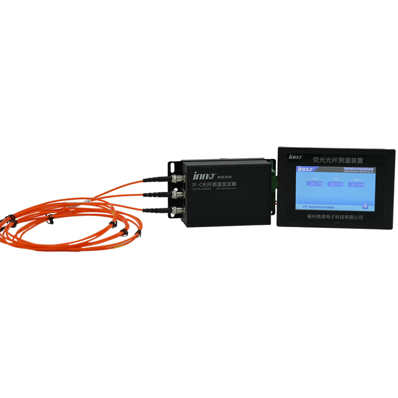
12.2.1 ال fiber optic temperature measurement system for oil-immersed transformers accommodates the winding hotspot sensors described above with a multi-channel transmitter unit supporting 1 ل 64 قنوات الاستشعار, RS485 Modbus RTU output, and local digital display. This is the principal instrument for مراقبة درجة حرارة لف المحولات in utility substation and industrial power applications.
12.2.2 ل dry-type transformer winding temperature monitoring, ال نظام قياس درجة حرارة الألياف الضوئية لملفات المحولات من النوع الجاف is configured for embedded sensor installations in resin-encapsulated coils with outputs for cooling fan control relay and protection trip integration.
12.2.3 ال fiber optic temperature online monitoring system for switchgear covers surface-mounted monitoring of busbar connections and cable terminations with a panel-mounted or DIN-rail-mounted transmitter and RS485 or Ethernet communication output.
12.3 Specialized and Custom Configurations
12.3.1 Applications requiring non-standard probe geometry, unusual fiber lengths, بروتوكولات الاتصال البديلة, or integration with specific SCADA platforms are supported through the customized fiber optic temperature measurement module development programme, which provides OEM and application-specific engineering support.
الأسئلة المتداولة
1. What is the most accurate temperature monitoring system for transformer windings?
Fluorescent fiber optic temperature sensors installed directly on winding conductors provide the highest accuracy and reliability for transformer winding hotspot measurement. They measure actual conductor surface temperature rather than estimating it from oil temperature and load current, and their optical signal path is immune to the electromagnetic fields inside transformer tanks at any operating voltage. For winding-interior applications at voltages above 1 كيلو فولت, no other sensor technology combines the necessary dielectric isolation, مناعة EMI, and direct-contact accuracy in a single solution.
2. Can a fiber optic temperature monitoring system be retrofitted to an in-service transformer?
Retrofit installation of fiber optic sensors into a transformer that is already in service requires an outage and tank-opening. The sensors are routed into the winding space through oil-tight glands in the tank wall, and the transformer must be partially drained and de-energised during installation. New transformer procurement is the preferred installation scenario, with sensors factory-installed during winding. For in-service retrofits where an outage is available, the long service life of the sensor system — typically exceeding 25 years — justifies the one-time installation cost over a conventional remaining-life assessment.
3. What winding hotspot temperature triggers an alarm under IEC 60076-7?
اللجنة الانتخابية المستقلة 60076-7 specifies a design hotspot temperature of 98 °C at rated load for transformers with a 65 K average winding temperature rise rating (the most common international standard). A first alarm is typically set at 110–115 °C, with a trip or forced load reduction at 120–130 °C depending on the asset management policy. For each 6 °C rise above 98 درجة مئوية, the insulation aging rate approximately doubles per the Montsinger relationship, so sustained operation at 110 °C represents approximately four times the design aging rate.
4. How does a wireless temperature monitoring system transmit signals through a metal-enclosed switchgear panel?
Sub-GHz radio frequencies (433 ميغاهيرتز, 868 ميغاهيرتز, 915 ميغاهيرتز) have significantly better penetration through metallic enclosures than 2.4 غيغاهيرتز. Wireless sensor systems designed specifically for switchgear applications use sub-GHz transceivers in both the sensor node and the external gateway, with antenna routing optimised for the specific switchgear enclosure geometry. Signal path and node placement should be verified by a site survey or manufacturer pilot test before full deployment, particularly in all-metal gas-insulated switchgear lineups where RF propagation is more constrained than in air-insulated metal-enclosed designs.
5. What is the difference between a winding temperature indicator (خام غرب تكساس الوسيط) and a fiber optic temperature monitoring system?
A conventional winding temperature indicator (خام غرب تكساس الوسيط) is a bimetallic dial thermometer that estimates winding hotspot temperature by adding an estimated winding gradient — modelled by a heating element carrying a current proportional to load — to the top-oil temperature it measures directly. It does not contact the winding. A fiber optic temperature monitoring system installs sensors directly on winding conductors and measures the actual conductor surface temperature. The estimation error of a WTI under non-standard operating conditions routinely reaches 10–20 °C; the fiber optic system measures the true hotspot regardless of load profile, cooling variation, or ambient condition.
6. How many fiber optic temperature channels does a typical power transformer require?
A minimum two-channel installation covering HV and LV winding hotspots is appropriate for distribution transformers at 11–66 kV. Four channels (الجهد العالي, LV, tap winding, and top-oil reference) are recommended for large distribution and sub-transmission transformers. Eight or more channels providing spatial distribution across winding height and between phases are standard for generator step-up transformers and large power transformers at 220 كيلو فولت وما فوق. يدعم جهاز إرسال واحد من الألياف الضوئية 1 ل 64 قنوات الاستشعار, so the channel count can be specified to match the transformer’s complexity without requiring multiple instruments.
7. What is the typical battery life of a wireless temperature sensor in switchgear, and how is it replaced?
Wireless sensor nodes powered by primary lithium batteries typically achieve 5–8 years of service at a 30–60 second reporting interval before battery replacement is required. Some designs extend this to 10 years by using adaptive reporting intervals that increase measurement frequency only when temperature is rising rapidly. Energy-harvesting models that extract power from the conductor’s magnetic field eliminate the battery replacement requirement entirely on conductors carrying sustained currents above approximately 150–200 A. Battery replacement on non-harvesting nodes requires a brief panel de-energisation or, on some designs, can be performed by removing the sensor node from its mounting bracket while the busbar remains live — check the manufacturer’s specific procedure for the product in question.
8. Can temperature monitoring detect a developing transformer core fault?
Core faults — circulating currents due to multi-point core grounding, lamination insulation breakdown, or core bolt insulation failure — generate localised heating in the core stack. If fiber optic sensors are positioned near the core-to-winding interface, an anomalous temperature rise in that region can provide early indication. لكن, core ground current monitoring is the primary diagnostic tool for core fault detection, with winding temperature trending providing corroborating evidence. The two should be specified together for high-value or ageing transformer assets.
9. What standards govern the accuracy calibration of fiber optic temperature sensors for IEC 60076-7 thermal calculations?
اللجنة الانتخابية المستقلة 60076-7 requires that the temperature measurement inputs to its thermal model be sufficiently accurate to support the aging rate calculation. في الممارسة العملية, calibration traceability to IEC 60751 (platinum resistance thermometer standard) accuracy Class B or better — corresponding to ±0.3 °C at 0 °C — is the accepted benchmark. INNO fluorescent fiber optic sensors are factory-calibrated to IEC 60751 traceable accuracy, with calibration certificates provided as part of the system documentation package.
10. Is continuous temperature monitoring cost-effective for distribution transformers, or only for large transmission units?
The cost-benefit assessment shifts as transformer criticality, replacement cost, and outage consequence increase. For transmission-class and large sub-transmission transformers (فوق 30 MVA or above 110 كيلو فولت), continuous fiber optic temperature monitoring is standard practice in most utilities because the asset replacement cost and grid impact of an unplanned outage dwarf the monitoring system cost. For distribution transformers below 10 MVA in non-critical locations, periodic oil sampling and conventional WTI remain the norm. For distribution transformers serving critical loads — hospital substations, data centre primary feeds, urban underground networks with long replacement lead times — continuous temperature monitoring is increasingly specified regardless of MVA rating.

مستشعر درجة حرارة الألياف الضوئية, نظام مراقبة ذكي, الشركة المصنعة للألياف الضوئية الموزعة في الصين
 |
 |
 |